EP0926358B2 - Caractéristique d'un joint tenon et mortaise combiné - Google Patents
Caractéristique d'un joint tenon et mortaise combiné Download PDFInfo
- Publication number
- EP0926358B2 EP0926358B2 EP98203924A EP98203924A EP0926358B2 EP 0926358 B2 EP0926358 B2 EP 0926358B2 EP 98203924 A EP98203924 A EP 98203924A EP 98203924 A EP98203924 A EP 98203924A EP 0926358 B2 EP0926358 B2 EP 0926358B2
- Authority
- EP
- European Patent Office
- Prior art keywords
- mortise
- panel
- tenon
- structure according
- Prior art date
- Legal status (The legal status is an assumption and is not a legal conclusion. Google has not performed a legal analysis and makes no representation as to the accuracy of the status listed.)
- Expired - Lifetime
Links
- 239000000853 adhesive Substances 0.000 claims description 26
- 230000001070 adhesive effect Effects 0.000 claims description 26
- 239000002131 composite material Substances 0.000 claims description 20
- 239000000463 material Substances 0.000 claims description 9
- 229920001169 thermoplastic Polymers 0.000 claims description 5
- 239000004416 thermosoftening plastic Substances 0.000 claims description 5
- RLLPVAHGXHCWKJ-IEBWSBKVSA-N (3-phenoxyphenyl)methyl (1s,3s)-3-(2,2-dichloroethenyl)-2,2-dimethylcyclopropane-1-carboxylate Chemical compound CC1(C)[C@H](C=C(Cl)Cl)[C@@H]1C(=O)OCC1=CC=CC(OC=2C=CC=CC=2)=C1 RLLPVAHGXHCWKJ-IEBWSBKVSA-N 0.000 claims 1
- 238000000034 method Methods 0.000 description 19
- 230000008901 benefit Effects 0.000 description 8
- 238000004519 manufacturing process Methods 0.000 description 6
- 238000005304 joining Methods 0.000 description 4
- 230000015572 biosynthetic process Effects 0.000 description 3
- 238000010276 construction Methods 0.000 description 2
- 230000000694 effects Effects 0.000 description 2
- 230000002452 interceptive effect Effects 0.000 description 2
- 238000004026 adhesive bonding Methods 0.000 description 1
- 239000011825 aerospace material Substances 0.000 description 1
- 230000004075 alteration Effects 0.000 description 1
- XAGFODPZIPBFFR-UHFFFAOYSA-N aluminium Chemical compound [Al] XAGFODPZIPBFFR-UHFFFAOYSA-N 0.000 description 1
- 229910052782 aluminium Inorganic materials 0.000 description 1
- 238000009435 building construction Methods 0.000 description 1
- 238000010348 incorporation Methods 0.000 description 1
- 230000000149 penetrating effect Effects 0.000 description 1
- 238000006467 substitution reaction Methods 0.000 description 1
- 239000002023 wood Substances 0.000 description 1
Images



Classifications
-
- A—HUMAN NECESSITIES
- A47—FURNITURE; DOMESTIC ARTICLES OR APPLIANCES; COFFEE MILLS; SPICE MILLS; SUCTION CLEANERS IN GENERAL
- A47B—TABLES; DESKS; OFFICE FURNITURE; CABINETS; DRAWERS; GENERAL DETAILS OF FURNITURE
- A47B43/00—Cabinets, racks or shelf units, characterised by features enabling folding of the cabinet or the like
- A47B43/02—Cabinets, racks or shelf units, characterised by features enabling folding of the cabinet or the like made of cardboard or the like
-
- F—MECHANICAL ENGINEERING; LIGHTING; HEATING; WEAPONS; BLASTING
- F16—ENGINEERING ELEMENTS AND UNITS; GENERAL MEASURES FOR PRODUCING AND MAINTAINING EFFECTIVE FUNCTIONING OF MACHINES OR INSTALLATIONS; THERMAL INSULATION IN GENERAL
- F16B—DEVICES FOR FASTENING OR SECURING CONSTRUCTIONAL ELEMENTS OR MACHINE PARTS TOGETHER, e.g. NAILS, BOLTS, CIRCLIPS, CLAMPS, CLIPS OR WEDGES; JOINTS OR JOINTING
- F16B12/00—Jointing of furniture or the like, e.g. hidden from exterior
- F16B12/10—Jointing of furniture or the like, e.g. hidden from exterior using pegs, bolts, tenons, clamps, clips, or the like
- F16B12/12—Jointing of furniture or the like, e.g. hidden from exterior using pegs, bolts, tenons, clamps, clips, or the like for non-metal furniture parts, e.g. made of wood, of plastics
- F16B12/125—Jointing of furniture or the like, e.g. hidden from exterior using pegs, bolts, tenons, clamps, clips, or the like for non-metal furniture parts, e.g. made of wood, of plastics using mortise and tenon joints
-
- F—MECHANICAL ENGINEERING; LIGHTING; HEATING; WEAPONS; BLASTING
- F16—ENGINEERING ELEMENTS AND UNITS; GENERAL MEASURES FOR PRODUCING AND MAINTAINING EFFECTIVE FUNCTIONING OF MACHINES OR INSTALLATIONS; THERMAL INSULATION IN GENERAL
- F16B—DEVICES FOR FASTENING OR SECURING CONSTRUCTIONAL ELEMENTS OR MACHINE PARTS TOGETHER, e.g. NAILS, BOLTS, CIRCLIPS, CLAMPS, CLIPS OR WEDGES; JOINTS OR JOINTING
- F16B2200/00—Constructional details of connections not covered for in other groups of this subclass
- F16B2200/10—Details of socket shapes
-
- Y—GENERAL TAGGING OF NEW TECHNOLOGICAL DEVELOPMENTS; GENERAL TAGGING OF CROSS-SECTIONAL TECHNOLOGIES SPANNING OVER SEVERAL SECTIONS OF THE IPC; TECHNICAL SUBJECTS COVERED BY FORMER USPC CROSS-REFERENCE ART COLLECTIONS [XRACs] AND DIGESTS
- Y10—TECHNICAL SUBJECTS COVERED BY FORMER USPC
- Y10T—TECHNICAL SUBJECTS COVERED BY FORMER US CLASSIFICATION
- Y10T403/00—Joints and connections
- Y10T403/49—Member deformed in situ
- Y10T403/4966—Deformation occurs simultaneously with assembly
Definitions
- This invention relates to the field of building construction using mortise and tenon joints to connect structural members in aerospace commodities, and more particularly, to the use of minimum edge margin mortise and tenon joints which implement self tooling characteristics to produce overhead stowage bins for aircraft from a single folded composite sandwich panel.
- the rabbet joint has become the standard design for the majority of aerospace commodities that utilize extended tab and pocket cutout joinery.
- the pocket cutouts are at the very edge of the panel, with the pocket sidewalls actually incorporated into the outer edge of the panel.
- This type of joint permits joint location to occur at the edge of a panel, thus providing the benefit of a non-interfering edge profile.
- the disadvantage of the rabbet joint is that the joint must be adhesive bonded to secure the panel connection, and the primary load path is through the relatively weak adhesive bondline at the rabbet joint.
- mortise and tenon joint The standard alternate to the rabbet joint is commonly referred to as a mortise and tenon joint.
- mortise and tenon has become somewhat generic in fine carpentry uses
- aerospace usage has defined a mortise and tenon joint as a term of art, describing a joint utilizing sandwich panel construction with square cut tabs (tenons) and blind (joint not visible after joining has occurred) slotted pocket cutouts (mortises), without dovetailing.
- the bonding process of a mortise and tenon joint also involves applying adhesive into the mortise pocket; however, since the pocket is fully enclosed in the mortise panel (not incorporated into the panel edge as in the rabbet joint), the primary load path is through the mortise panel itself and not the adhesive bondline.
- the disadvantage of the mortise and tenon joint is the existence of an edge margin of the mortise panel that extends from the mortise pocket to the actual edge of the panel. This interfering edge margin reduces the volume which can be achieved inside a defined envelope. It is desirable to have a joint that would provide the combined benefits of both a rabbet joint and a mortise and tenon joint.
- overhead stowage bins for aircraft are produced by joining together four (typically) composite sandwich panels using structural adhesives and either aluminum brackets fastened to potted inserts or modified box joints (typically rabbet joints). Both of these methods depend on the strength of the adhesives to carry the required structural loads.
- the present invention discloses a one-piece aircraft overhead stowage bin constructed from a single piece of folded, thermoplastic-composite-skinned, honeycomb-cored sandwich panel.
- the aircraft stowage bin is formed by folding the composite material into a locking open box type structure.
- the composite sandwich panel contains interlocking joints which can be characterized as minimum edge margin mortise and tenon joints (described below).
- a minimum edge-margin mortise and tenon joint corner structure is formed from a tenon panel, having tenon tabs, engaging mortise pockets formed in an angularly disposed tenon panel.
- the mortise pockets are located along the edge of the mortise panel, as in a rabbet joint, but with the mortise panel edge containing outwardly extended bulges in the regions of the mortise pockets, such that a minimum edge margin is maintained around each mortise pocket (instead of the pockets being incorporated into the panel edge as in a rabbet joint).
- the single piece thermoplastic composite honeycomb sheet is cut so that sections of the sheet can be folded, using a thermoplastic folding method, to form the stowage bin.
- Side portions of the sheet are designed such that their shape facilitates being folded upwards to form end panels of the stowage bin.
- Another portion of the sheet is designed such that its shape facilitates being folded upwards and then over, to form the top panel of the stowage bin.
- the minimum edge margin mortise and tenon joints are used at the connection between the top edge of the end panels and the top panel of the stowage bin.
- the mortise pockets in the mortise portion of the panel joint are located along the edge of the top panel of the stowage bin.
- the tenon tabs in the tenon portion of the panel joint are located along the top edge of the end panels. This allows the minimum edge margin mortise and tenon joints to engage during the folding process of the stowage bin panel.
- two formed angle brackets are through-bolted to the top panel of the stowage bin and the end panels. This provides a load path for downloading forces and securely locks the bin together.
- This locking method which utilizes the formed angle brackets, allows the folded composite panel to form joints that connect such that no adhesive is required, either to carry loading forces or to hold the bin together. The only direction in which the minimum edge margin mortise and tenon joint is subject to detachment during loaded conditions, is secured by the formed angle brackets.
- the invention discloses a self aligning mortise and tenon joint structure that is formed from angularly arranged tenon and mortise panels, having tenon tabs and mortise pockets, respectively.
- mortise and tenon joints constructed of composite honeycomb material, the mortise pockets in the mortise panel must be cut sufficiently larger than the optimal size of the extended tenon tab of the tenon panel, because of the inherent thickness variations in tenon panel production. Otherwise tenon panel thickness variation can cause an interference with the mortise pocket sidewalls, preventing the tenon tab from fitting in the mortise pocket.
- the mortise pocket sidewalls incorporate protrusions extending into the mortise pocket, the protrusions being distributed along the sidewalls of the mortise pocket.
- the tenon tabs will deflect these unsupported protrusions slightly and/or remove material from the tips of the protrusions at the points of contact, forming an interference fit.
- the protrusions thus act as a self-locating/self-tooling features both to locate the tenon in the center of the mortise, and so that if it is desired that bonding adhesive be used in the joint, the tenon panel is secured to the mortise panel until curing completion, without the assistance of additional tooling devices.
- a stowage bin constructed in accordance with the present invention may thus be formed from only a single piece of folded thermoplastic-composite-skinned sandwich sheet and two formed angle brackets.
- the lack of requirement for bonding adhesive greatly reduces manufacture time, since the adhesive application and adhesive curing stages are eliminated from the assembly process. Weight savings are also acquired from the reduction in part count (both in brackets and panels). Further, the incorporation of the minimum edge margin mortise and tenon joints gives the combined benefits of the non-interference edge profile of a rabbet joint, with the superior strength of a traditional mortise and tenon joint.
- this invention incorporates self-tooling features into the mortise pocket cutouts, that accommodate tenon panel thickness variations by a combination of local material removal and "spring” deflection of the unsupported protrusions to locate and maintain the tenon panel in the center of the mortise pocket cutout.
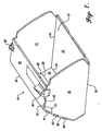
- FIGURE 1 illustrates a preferred embodiment of a one-piece aircraft stowage bin 10 constructed in accordance with the present invention and utilizing a folded composite sandwich panel and interlocking joints.
- the one piece stowage bin 10 has a bottom panel 12 which forms the bottom of the open box-type structure. Forming the side walls of the stowage bin 10 are right and left end panels 14 and 18 which rise up from the sides of the bottom panel 12.
- the remaining portion of the stowage bin 10 contains three fold lines which allow it to comprise the rear lower panel 22, the rear upper panel 26 and the top panel 30 of the stowage bin. It should be readily apparent that a greater or lesser number of rear panels could be utilized without departing from the general concept of the structure described herein.
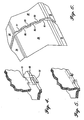
- FIGURE 2 shows tenons 51, 52, 53, 54, 57, 58, 59, and 60, which extend from the margins of the right and left end panels 14 and 18.
- Mortises 63, 64, 65, 66, 71, 72, 73, and 74 respectively are formed in the side margins of the rear upper panel 26 and the top panel 30. Together, the mortises 63, 64, 65, 66, 71, 72, 73, and 74, and tenons 51, 52, 53, 54, 57, 58, 59, and 60, create interlocking joints.
- right and left formed angle brackets 38 and 40 secure the right and left end panels 14 and 18 to the top panel 30.
- the overhead stowage bin 10 is constructed from a single sheet of thermoplastic-composite-skinned, honeycomb-cored sandwich.
- the composite sandwich sheet is originally flat, as shown in FIGURE 2 .
- the sheet is then folded using a thermofolding process into its final shape as shown in FIGURE 1 .
- a preferred thermofolding technique is described in patent application 08/712,987 , filed September 13, 1996.
- the intended fold lines for the formation of the bin's final shape is illustrated.
- Between the right edge panel 14 and the bottom panel 12 is the right/bottom panel fold line 16.
- Between the left end panel 18 and the bottom panel 12 is the left/bottom panel fold line 20.
- Between the rear lower panel 22 and the bottom panel 12 can seen be the rear lower/bottom panel fold line 24.
- Next in line, between the rear upper panel 26 and the rear lower panel 22 can be seen the upper/lower panel fold line 29.
- the top panel 30 and the rear upper panel 26 can be seen the top/upper panel fold line 33.
- the right and left end panel upper edges 15 and 19, could actually be foldlines where the right and left end panels 14 and 18 attached to the top panel 30.
- FIGURE 2 also discloses a right rear lower/end panel intersection notch 34 and a left rear lower/end panel intersection notch 36.
- These notches in the rear lower panel 22 are located just before the rear lower/bottom panel fold line 24. The function of these notches is to prevent an interference condition from occurring when the right and left end panels 14 and 18 and the rear lower panel 22 are all folded upwardly.
- the right and left intersection notches 34 and 36 facilitate the formation of a corner joint between these three intersecting planar surfaces.
- the shape of the completed overhead stowage bin 10 can be generally described as a rectangular, polygonal open-fronted box-type structure. Referring again to FIGURE 1 , it can be seen that the stowage bin 10 is generally rectangular when observed from a proximal (front) view of the open-fronted structure (right-hand side in FIGURE 1 ). As can be more clearly seen in FIGURE 3 , the stowage bin 10 can also be described generally as an asymmetrical six-sided polygon. The forward or inboard side of the stowage bin defines an opening 37 in the bin's completed final stage.
- the interlocking joints of the stowage bin 10 are a modified-type of mortise and tenon joint described as minimum edge margin mortise and tenon joints.
- This joint is formed from the intersection of an orthogonally disposed tenon panel and mortise panel.
- the tenon panel is illustrated as having "square cut” tenon tabs and the mortise panel is illustrated as having "square cut” mortise pocket cutouts with no dovetailing or other angling cut utilized in the sides or edges of the tenon tabs or mortise pocket cutouts.
- four right end panel tenon tabs 51, 52, 53, and 54 are located along the right end panel upper edge 15.
- the four left end panel tenon tabs 57, 58, 59, and 60 are located on the left end panel upper edge 19.
- the mortise pockets are located along the edge of the mortise panel as in a rabbet joint but with the mortise panel edge containing outwardly extended bulges in the region of the mortise pockets.
- This defines a minimum edge margin around each mortise pocket cutout instead of the mortise pocket sidewalls being incorporated directly into the panel edge as in a rabbet joint.
- An inherent advantage of the edge margin mortise and tenon joint of the present invention is that the load imposed on the joint extends through the minimum edge margin of the panel, instead of being forced through the bondline of an adhesive, which are commonly used to secure prior art joints.
- the panel together with the minimum edge margin can carry a substantially greater load than can an adhesive bondline.
- the stowage bin 10 utilizes eight minimum edge margin mortise pockets, four on the right and four on the left. Specifically, in the present invention there are three minimum edge margin mortise pockets 63, 64, and 65 on the rear upper panel right edge margin 27 and one minimum edge margin mortise pocket 66 on the top panel right outer edge 31. Correspondingly, there are three minimum edge margin mortise pockets 71, 72, and 73 on the rear upper panel left edge margin 28 and one left top panel minimum edge margin mortise pocket 74 on the top panel left outer edge 32.
- the right side wall tenon tabs 51, 52, 53, and 54 and the left side wall tenon tabs 57, 58, 59, and 60 are disposed along on the right and left end panel upper edges 15 and 19 respectively, so that a lateral load is carried through the edge margins of the mortise pockets 63, 64, 65, 66, 71, 72, 73, and 74.
- Alternative embodiments of this invention may utilize a greater or lesser number of minimum edge margin mortise pockets depending on the loading requirements for the particular applications involved.
- a limited number of folding sequences are needed to form the stowage bin 10.
- One preferred sequence is to first fold up the right and left end panels 14 and 18 along fold lines 16 and 20, and then fold the top panel 30, the rear upper panel 26 and rear lower panel 22 in that respective order. This particular folding sequence allows the mortise and tenons to engage together as the box structure is formed.
- the right mortise pockets 63, 64, 65, and 66 and right tenon tabs 51, 52, 53, and 54 do not align symmetrically with the left mortise pockets 71, 72, 73, and 74 and the left end panel tenon tabs 57, 58, 59, and 60, but rather are staggered relative to each other.
- This design allows two identical stowage bins (or indeed an entire row of stowage bins) to nest in close proximity to one another with the right extending minimum edge margin bulges 81, 82, 83, and 84 forming a "zipper-like" connection with the left extending minimum edge margin bulges 89, 90, 91, and 92 of an identical adjacent bin.
- the outer longitudinal sidewalls 163, 164, 165, and 166 are the longitudinal sidewalls of the right mortise pockets 63, 64, 65, and 66 that are the closest to the rear upper panel right edge margin 27 and the top panel right edge margin 31.
- the outer longitudinal sidewalls 163, 164, 165, and 166 are in linear alignment with the rear upper panel right edge margin 27 and the top panel right edge margin 31, with only the right minimum edge margin bulges 81, 82, 83, and 84 extending beyond the right panel edge margins 27 and 31.
- This type of minimum edge margin mortise and tenon joint design allows the volume of the stowage bin 10 to be maximized.
- the outer longitudinal sidewalls 171, 172, 173, and 174 are the longitudinal sidewalls of the left mortise pockets 71, 72, 73, and 74 that are the closest to the rear upper panel left edge margin 28 and the top panel left edge margin 32.
- the outer longitudinal sidewalls 171, 172, 173, and 174 are in linear alignment with the rear upper panel left edge margin 28 and the top panel left edge margin 32, with only the left minimum edge margin bulges 89, 90, 91, and 92 extending beyond the left panel edge margins 28 and 32.
- Alternative embodiments of this invention might vary the location and alignment of the mortise pockets along the panel edge margins and with respect to the pocket's respective minimum edge margin bulges to accommodate specific applications.
- the mortise pockets are illustrated as not penetrating the entire thickness of the rear upper panel 26 or the top panel 30.
- the mortise pocket cutouts penetrate through one side of the thermoplastic composite skin and the honeycomb core, but not through the second side of the thermoplastic composite skin.
- the length of the extended tenon tabs from the left and right end panels 14 and 18 should approximate the depth of the mortise pockets for preferred nesting of the interlocking joint. This type of joint is referred to as a "blind joint" since the joining method cannot be seen after the joint is engaged.
- the mortise pockets may penetrate the entire thickness of the composite panel.
- the mortise pocket may penetrate through the entire thickness of the mortise panel.
- the load path through the joint extends through both the upper and lower skins of the mortise panel since both skins are in contact with the tenon. This provides a stronger, larger load carrying capacity joint, especially if no adhesive is used at the joint.
- Brackets 38 and 40 secure the top panel 30 to the right and left end panels 14 and 18, as shown in FIGURE 1 .
- the top and end flanges of the brackets 38 and 40 are through-bolted, respectively, to the top panel 30 of the bin and the end panels 14 and 18 such that the brackets provide a load path for downloads imposed on the bottom panel 12, locking the box together so that the tenon tabs cannot be pulled out of the mortise pockets.
- only these two brackets 38 and 40 are required to hold the one piece stowage bin together. This is a substantial reduction in part count as well as weight savings providing substantial advantages over alternatives in the prior art.
- This folded one piece composite panel stowage bin 10 has the added advantage of not requiring a bonding adhesive.
- the use of adhesive bonding of joints has virtually always been necessary in aerospace joinery techniques that utilize composite materials.
- the removal of bonding adhesive for securing joints eliminates substantial application and cure time of the adhesive, generally on the order of eight hours. It can also eliminate the need for expensive and complicating tooling. Thus, both time and money can be saved in the production of a stowage bin 10 that does not require adhesive for securing its joints.
- FIGURE 7 Another aspect of the present invention is shown in FIGURE 7 , which illustrates the utilization of self-tooling characteristics into the mortise and tenon joint.
- the right and left square cut tenon tabs 51, 52, 53, 54, 57, 58, 59, and 60 are produced substantially smaller than their corresponding right and left mortise pocket counterparts 63, 64, 65, 66, 71, 72, 73, and 74. This methodology helps to ensure that variation in tenon panel thickness does not prevent the tenon tabs from being able to engage in the mortise pockets.
- the present invention incorporates protrusions 120a into the sidewalls and endwalls of the mortise pockets 63, 64, 65, 66, 71, 72, 73, and 74 that extend into the interior of the mortise pockets.
- These protrusions are illustrated in FIGURE 7 as being of wave-like or generally semi-circular shape, and are sized to form an interference fit with the tenon tabs when they engage into their respective mortise pockets.
- the interference fit is achieved through a combination of spring deflection of the wave-like protrusions by the tenon tabs and local material removal from the tips of the "waves" as the tenons are inserted.
- the wave-like protrusions are disposed along both longitudinal sidewalls of the mortise pockets to secure the tenon tab in the center of the mortise pocket.
- the wave like protrusions could be disposed only along one longitudinal sidewall so that the opposite longitudinal sidewall would be forced into substantially full contact with the adjacent surface of the extended tenon tab, for use in specific applications.
- the wave-like protrusions act as self-tooling component of the joint, that is capable of independently securing the tenon panel to the mortise panel, without the assistance of expensive additional tooling.
- the protrusions 120a may be formed in shapes other than as illustrated and described above.
- the protrusions can be in the shape of peaks, truncated peaks, triangles, truncated triangles, saw teeth, truncated saw teeth, etc. See FIGURES 8 and 9 , and protrusions 120b and 120c respectively in this regard.
- the protrusions are tapered in the direction into the interior of the mortise pockets.
- the mortise pocket can be formed in shapes other than the rectangular shape shown in FIGURES 4, 5 , and 7 .
- the mortise pocket can be square, oval, round, etc.
- the tenon is shaped to snugly engage the mortise pocket.
- the present invention may be utilized in conjunction with mortise and tenon panels that are disposed at angles other than orthogonally to each other, as shown in FIGURES 4 and 5 .
- the mortise and tenon joint of the present invention may be utilized with mortise and tenon panels that are disposed anywhere from 45° to 135° relative to each other.
- the mortise pocket is formed in the desired angle relative to the surface of the mortise panel.
- the edge of the tenon panel adjacent the tenon tab is angled accordingly.
Landscapes
- Engineering & Computer Science (AREA)
- General Engineering & Computer Science (AREA)
- Mechanical Engineering (AREA)
- Connection Of Plates (AREA)
- Cartons (AREA)
Claims (22)
- Structure de joint à tenon et mortaise à auto-alignement, comprenant :- un panneau à mortaise ayant des portions définissant au moins une cavité de mortaise (63, 64, 65, 66, 71, 72, 73, 74) dans le panneau à mortaise ;- un panneau à tenon comprenant au moins une languette de tenon (51, 52, 53, 54, 57, 58, 59, 60) saillant depuis le panneau à tenon, la languette de tenon étant formée pour correspondre à la forme en section transversale de la cavité de mortaise, ladite languette de tenon saillante (51, 52, 53, 54, 57, 58, 59, 60) pouvant s'engager dans ladite cavité de mortaise (63, 64, 65, 66, 71, 72, 73, 74), les panneaux étant constitués d'un matériau composite en nid d'abeilles ; caractérisée par :- au moins une saillie (120a, 120b, 120c) s'étendant vers l'intérieur depuis la paroi périphérique de la cavité de mortaise et à l'intérieur de la cavité de mortaise, ladite saillie étant dimensionnée pour former un joint à ajustement serré avec la languette de tenon engagée dans la cavité de mortaise par une combinaison d'enlèvement de matière locale et de déflexion à ressort de la saillie par la languette de tenon, ladite saillie agissant comme un élément auto-enveloppant, capable de fixer indépendamment le panneau à tenon au panneau de mortaise.
- Structure selon la revendication 1, dans laquelle les saillies (120a, 120b, 120c) sont situées uniquement le long d'une portion de la paroi périphérique de la cavité de mortaise (63, 64, 65, 66, 71, 72, 73, 74), de telle sorte que la languette de tenon (51, 52, 53, 54, 57, 58, 59, 60) soit forcée en contact substantiellement total avec la portion de la paroi périphérique de la cavité de mortaise ne présentant pas de saillies.
- Structure selon la revendication 1 or 2, dans laquelle le panneau à mortaise est positionné non perpendiculairement au panneau à tenon.
- Structure selon l'une quelconque des revendications 1 à 3, dans laquelle le panneau à tenon est disposé suivant un angle de 45° à 135° par rapport au panneau à tenon.
- Structure selon l'une quelconque des revendications 1 à 4, dans laquelle le joint à ajustement serré créé entre les saillies (120a, 120b, 120c) de la cavité de mortaise (63, 64, 65, 66, 71, 72, 73, 74) et la languette de tenon insérée (51, 52, 53, 54, 57, 58, 59, 60) du panneau à tenon a un dégagement d'environ -0,0254 mm à -1,016 mm (-0,001 à -0,040 pouce).
- Structure selon l'une quelconque des revendications 1 à 5, dans laquelle la cavité de mortaise (63, 64, 65, 66, 71, 72, 73, 74) du joint à tenon et mortaise à auto-alignement est remplie d'un adhésif de liaison.
- Structure selon l'une quelconque des revendications précédentes, dans laquelle la saillie (120a, 120b, 120c) est capable de supporter indépendamment le panneau à tenon et le panneau à mortaise engagés l'un dans l'autre tant que l'adhésif de liaison n'est pas durci.
- Structure selon l'une quelconque des revendications précédentes, comprenant :- au moins une languette de tenon (51, 52, 53, 54, 57, 58, 59, 60) s'étendant vers l'extérieur depuis le panneau à tenon, ladite languette ayant des surfaces latérales qui sont agencées angulairement par rapport au plan défini par le panneau de mortaise ;- ledit organe de panneau à mortaise définissant au moins une cavité de mortaise (63, 64, 65, 66, 71, 72, 73, 74) dans le panneau à mortaise, ladite cavité de mortaise ayant généralement une forme correspondant à la forme en section transversale de la languette de tenon, ladite découpure du panneau à mortaise définissant une paroi périphérique intérieure ;- l'organe de panneau à mortaise définissant une marge de bord avec la cavité de mortaise adjacente à ladite marge de bord, la marge de bord ayant des portions définissant un bombement (81, 82, 83, 84, 89, 90, 91, 92) qui s'étend vers l'extérieur depuis la marge de bord du panneau à mortaise dans la région de la cavité de mortaise, de telle sorte que la marge de bord conserve une largeur minimale autour de la cavité de mortaise ;- la portion de la paroi périphérique intérieure de la cavité de mortaise la plus proche de la marge de bord du panneau à mortaise étant définie comme la paroi latérale longitudinale externe, ladite paroi latérale longitudinale externe étant alignée avec les portions non bombées de la marge de bord du panneau à mortaise ; et- les panneaux à tenon et mortaise étant composés d'un matériau composite en nid d'abeilles dans lequel l'engagement de la languette de tenon dans la cavité de mortaise produit un espacement nominal entre la paroi périphérique intérieure de mortaise et la surface adjacente de la languette de tenon, de l'ordre d'environ 0,508 mm (0,020 pouce).
- Structure selon l'une quelconque des revendications précédentes, dans laquelle le panneau à mortaise contient une pluralité de bombements de marge de bord minimaux (81, 82, 83, 84, 89, 90, 91, 92) entourant chacune des cavités de mortaise correspondantes (63, 64, 65, 66, 71, 72, 73, 74).
- Structure selon l'une quelconque des revendications précédentes, dans laquelle la pluralité de cavités de mortaise (63, 64, 65, 66, 71, 72, 73, 74) ont leurs parois latérales longitudinales externes alignées avec la marge de bord de panneau à mortaise comme défini par les portions non bombées de la marge de bord du panneau à mortaise.
- Structure selon l'une quelconque des revendications précédentes, dans laquelle la cavité de mortaise (63, 64, 65, 66, 71, 72, 73, 74) s'étend uniquement en partie à travers l'épaisseur du panneau à mortaise.
- Structure selon l'une quelconque des revendications 1 à 10, dans laquelle la cavité de mortaise (63, 64, 65, 66, 71, 72, 73, 74) pénètre entièrement à travers le panneau à mortaise.
- Structure selon l'une quelconque des revendications 8 à 12, dans laquelle les bombements de marge de bord minimaux (81, 82, 83, 84, 89, 90, 91, 92) ont une longueur au moins aussi longue que la longueur de la cavité de mortaise (63, 64, 65, 66, 71, 72, 73, 74) s'étendant le long de la paroi latérale longitudinale externe du panneau à mortaise.
- Structure selon l'une quelconque des revendications précédentes, comprenant en outre :- une feuille unique de matériau, pliée suivant une structure de type boîte à devant ouvert, comprenant un panneau inférieur (12), des panneaux d'extrémité droit (14) et gauche (18), au moins un panneau arrière (22, 26) et un panneau supérieur (30), les panneaux d'extrémité droit et gauche étant pliés par rapport aux côtés d'un panneau choisi parmi le groupe constitué du panneau inférieur (12), de l'au moins un panneau arrière (22, 26) et du panneau supérieur (30), pour ainsi former les panneaux d'extrémité de la structure de type boîte, le panneau du groupe par rapport auquel sont pliés les panneaux d'extrémité étant appelé panneau intégral et les deux autres panneaux du groupe étant appelés panneaux joints ;- l'au moins un panneau arrière (22, 26) plié vers le haut depuis le panneau inférieur (12), et le panneau supérieur (30) s'étendant vers l'avant depuis le dessus de l'au moins un panneau arrière ;- les panneaux d'extrémité gauche (18) et droit (14) ayant des marges de bord et les panneaux joints ayant des marges de bord adjacentes aux marges de bord des panneaux d'extrémité ;- une pluralité de cavités de mortaise (63, 64, 65, 66, 71, 72, 73, 74) espacées soit le long des marges de bord des panneaux d'extrémité droit et gauche soit des marges de bord des panneaux joints, et des bombements s'étendant vers l'extérieur depuis les cavités de mortaise vers les marges de bord afin de maintenir une marge de bord d'une largeur minimale le long de chaque cavité de mortaise ; et- des languettes de tenon (51, 52, 53, 54, 57, 58, 59, 60) s'étendant depuis les marges de bord de l'autre des panneaux d'extrémité gauche et droit et des panneaux joints pour s'engager avec une cavité de mortaise correspondante pour former avec eux un joint à tenon et mortaise à emboîtement ;- la structure comprenant des cornières formées (3 8, 40), lesdites cornières étant attachées au panneau supérieur et aux panneaux d'extrémité, pour ainsi fournir un chemin de charge pour les charges appliquées sur le panneau inférieur et pour verrouiller l'ensemble de la structure ;- le panneau étant constitué d'un matériau à peau composite thermoplastique, en sandwich à coeur en nid d'abeilles ;- une pluralité de saillies étant positionnées le long des parois latérales de la cavité de mortaise, le panneau à tenon étant positionné et maintenu généralement au centre de la cavité de mortaise (63, 64, 65, 66, 71, 72, 73, 74).
- Structure selon l'une quelconque des revendications précédentes, dans laquelle la saillie (120a, 120b, 120c) est effilée dans la direction de l'intérieur de la cavité.
- Structure selon la revendication 15, dans laquelle la forme des saillies (120a, 120b, 120c) est choisie parmi le groupe constitué d'ondulations, d'ondulations tronquées, de pics, de pics tronqués, de dents de scie, de dents de scie tronquées, de demi-cercles, de demi-cercles tronqués, de triangles, et de triangles tronqués.
- Structure selon la revendication 16, dans laquelle lesdites saillies (120a, 120b, 120c) sont en forme d'ondulations et comprennent une courbe de forme généralement circulaire dans la direction en travers de la courbure, avec un grand rayon d'environ 1,6 mm (0,063 pouce) et un petit rayon d'environ 3,175 mm (0,125 pouce), les saillies comprenant aussi des pointes de saillie qui s'étendent approximativement sur 1,143 mm (0,045 pouce) dans l'intérieur de la cavité de mortaise (63, 64, 65, 66, 71, 72, 73, 74).
- Structure selon l'une quelconque des revendications 14 à 17, dans laquelle la peau thermoplastique du panneau en sandwich de la structure reste non découpée dans son état après le pliage, la peau étant en mesure de porter une portion du chemin de charge.
- Structure selon l'une quelconque des revendications précédentes, dans laquelle les cavités de mortaise (63, 64, 65, 66, 71, 72, 73, 74) sont situées uniquement sur les marges de bord des panneaux joints et les languettes de tenon (51, 52, 53, 54, 57, 58, 59, 60) sont situées uniquement le long des marges de bord correspondantes des panneaux d'extrémité, le chemin de charge dans la direction latérale étant porté par la marge de bord de largeur minimale entourant chaque cavité de mortaise.
- Structure selon l'une quelconque des revendications 8 à 19, dans laquelle les saillies créées par les bombements de marge de bord (81, 82, 83, 84, 89, 90, 91, 92) sont uniquement dans les directions avant et arrière.
- Structure selon l'une quelconque des revendications précédentes, dans laquelle les emplacements de tenon et mortaise avant et arrière de la structure sont décalés les uns par rapport aux autres, ce qui permet à la structure de s'imbriquer avec une autre structure identique et d'avoir un espace minimum requis entre les structures.
- Structure selon l'une quelconque des revendications 14 à 21, dans laquelle deux cornières formées maintiennent substantiellement la position de la structure indépendamment.
Priority Applications (1)
| Application Number | Priority Date | Filing Date | Title |
|---|---|---|---|
| DE69835935T DE69835935T3 (de) | 1997-11-20 | 1998-11-19 | Kombiniertes Zapfenverbindungsmerkmal |
Applications Claiming Priority (2)
| Application Number | Priority Date | Filing Date | Title |
|---|---|---|---|
| US08/974,948 US6164477A (en) | 1997-11-20 | 1997-11-20 | Combined mortise and tenon joint feature |
| US974948 | 1997-11-20 |
Publications (4)
| Publication Number | Publication Date |
|---|---|
| EP0926358A2 EP0926358A2 (fr) | 1999-06-30 |
| EP0926358A3 EP0926358A3 (fr) | 2004-03-17 |
| EP0926358B1 EP0926358B1 (fr) | 2006-09-20 |
| EP0926358B2 true EP0926358B2 (fr) | 2011-04-13 |
Family
ID=25522545
Family Applications (1)
| Application Number | Title | Priority Date | Filing Date |
|---|---|---|---|
| EP98203924A Expired - Lifetime EP0926358B2 (fr) | 1997-11-20 | 1998-11-19 | Caractéristique d'un joint tenon et mortaise combiné |
Country Status (3)
| Country | Link |
|---|---|
| US (2) | US6164477A (fr) |
| EP (1) | EP0926358B2 (fr) |
| DE (1) | DE69835935T3 (fr) |
Families Citing this family (28)
| Publication number | Priority date | Publication date | Assignee | Title |
|---|---|---|---|---|
| US6164477A (en) * | 1997-11-20 | 2000-12-26 | The Boeing Company | Combined mortise and tenon joint feature |
| US6976992B2 (en) * | 2002-07-16 | 2005-12-20 | Suturecut, Llc | Dual-function medical instrument |
| US6968971B2 (en) * | 2002-08-07 | 2005-11-29 | The Boeing Company | Endcap assembly for a stowage bin |
| US6782672B2 (en) | 2002-10-08 | 2004-08-31 | Alliance Spacesystems, Inc. | Sandwich panel structural joint |
| DE102004014565B4 (de) | 2004-03-25 | 2022-09-01 | Volkswagen Ag | Clipsverbindung |
| US7641414B1 (en) | 2004-09-04 | 2010-01-05 | Joyce Jared L | Furniture and joint systems |
| US7914091B1 (en) | 2004-09-04 | 2011-03-29 | Joyce Jared L | Furniture systems |
| US7766063B2 (en) * | 2005-04-28 | 2010-08-03 | The Boeing Company | Machine assisted laminator and method |
| US7887249B2 (en) * | 2006-06-15 | 2011-02-15 | The Boeing Company | Internal finger joint |
| US20080317530A1 (en) * | 2007-06-19 | 2008-12-25 | Kabushiki Kaisha Toshiba | Fastening structure for rotating member |
| US8029642B2 (en) | 2007-07-27 | 2011-10-04 | The Boeing Company | Tape removal apparatus and process |
| US8345269B2 (en) | 2007-09-22 | 2013-01-01 | The Boeing Company | Method and apparatus for measuring the width of composite tape |
| US8234901B2 (en) | 2007-10-25 | 2012-08-07 | The Boeing Company | Method to create bends in composite panels |
| US8312754B2 (en) | 2007-10-25 | 2012-11-20 | The Boeing Company | Method for forming bends in composite panels and composite panels made thereby |
| US7922856B2 (en) | 2008-01-02 | 2011-04-12 | The Boeing Company | Graphite tape supply and backing paper take-up apparatus |
| US8557074B2 (en) | 2008-02-27 | 2013-10-15 | The Boeing Company | Reduced complexity automatic fiber placement apparatus and method |
| US8986482B2 (en) | 2008-07-08 | 2015-03-24 | The Boeing Company | Method and apparatus for producing composite structures |
| US8308101B2 (en) | 2009-03-09 | 2012-11-13 | The Boeing Company | Simplified fiber tensioning for automated fiber placement machines |
| US8454788B2 (en) | 2009-03-13 | 2013-06-04 | The Boeing Company | Method and apparatus for placing short courses of composite tape |
| US8267269B2 (en) * | 2009-10-09 | 2012-09-18 | Craig Gundersen | Collapsible food guard, display and server |
| US8961059B2 (en) | 2012-09-06 | 2015-02-24 | The Boeing Company | Self-locking joints for panel structures and methods of fabricating the same |
| US8973241B1 (en) | 2012-09-06 | 2015-03-10 | The Boeing Company | Method and apparatus for joining composite structures |
| US9205616B2 (en) | 2013-10-11 | 2015-12-08 | The Boeing Company | Bends in composite panels |
| US9468298B2 (en) * | 2014-02-12 | 2016-10-18 | Matthew E Gerstle | Recycled corrugated child's chair |
| US9738386B2 (en) * | 2015-04-09 | 2017-08-22 | The Boeing Company | Overhead stowage bin assembly for a vehicle |
| EP3500488B1 (fr) | 2016-08-16 | 2021-01-27 | Safran Cabin Inc. | Bac de compartiment de rangement d'aéronef avec joint d'angle à encombrement efficace |
| US10746215B2 (en) * | 2017-05-05 | 2020-08-18 | The Boeing Company | Blade-and-slot joints that unite composite panels via internal blades |
| US11077630B1 (en) * | 2020-02-04 | 2021-08-03 | The Boeing Company | Molded laminated structure with negative draft angles and associated methods of manufacturing |
Citations (17)
| Publication number | Priority date | Publication date | Assignee | Title |
|---|---|---|---|---|
| GB191301965A (en) † | 1913-01-24 | 1913-08-28 | Frederick John Pugsley | Improvements in Foldable Stationery Cases. |
| US1944984A (en) † | 1931-07-17 | 1934-01-30 | George H Klippel | Draft attachment for furnaces and the like |
| US2145615A (en) † | 1935-09-16 | 1939-01-31 | New England Box Company | Light plywood shipping container |
| US2439998A (en) † | 1943-02-26 | 1948-04-20 | Zalkind Philip | Fibre reinforced collapsible container |
| US2764461A (en) † | 1953-11-19 | 1956-09-25 | Henry M Montgomery | Box means |
| US3429199A (en) † | 1966-02-04 | 1969-02-25 | Robertshaw Controls Co | Switch construction and method |
| DE1924252A1 (de) † | 1969-05-12 | 1970-11-19 | Hasslauer Dipl Ing Rainer | Pappmoebel |
| US3752553A (en) † | 1971-07-29 | 1973-08-14 | Amerock Corp | Drawer with snap-on front panel |
| DE2718002C3 (de) † | 1977-04-22 | 1981-11-05 | Roland 6231 Schwalbach Sommer | Mehrschichtiger plattenförmiger Verbundwerkstoff |
| EP0115592A1 (fr) † | 1983-02-03 | 1984-08-15 | Karl Stefan Drabsch | Assemblage à mortaise et tenon pour tréteaux en bois |
| DE3820396A1 (de) † | 1988-06-15 | 1989-12-28 | Wilhelm Von Dipl Ing Dreden | Holzzapfenverbindung |
| US5123463A (en) † | 1991-04-24 | 1992-06-23 | Grisley Kenneth M | Mortise and tenon jig for a router |
| FR2679743A1 (fr) † | 1991-07-31 | 1993-02-05 | Woytasik Raymond | Volume de rangement modulaire. |
| US5316156A (en) † | 1993-01-04 | 1994-05-31 | Land Marty W | Display rack |
| US5357728A (en) † | 1989-05-03 | 1994-10-25 | Duncanson Robert J | Jointing of building panels and sheets |
| DE29609442U1 (de) † | 1996-05-28 | 1996-09-26 | Steinhoff Laminat GmbH, 37327 Leinefelde | Formteil |
| JPH0921185A (ja) † | 1995-07-06 | 1997-01-21 | Takeshi Yamada | かま継手 |
Family Cites Families (23)
| Publication number | Priority date | Publication date | Assignee | Title |
|---|---|---|---|---|
| GB642297A (en) * | 1948-09-21 | 1950-08-30 | Hoover Ltd | Improvements relating to the securing of shafts in synthetic resin mouldings |
| US3330437A (en) * | 1966-01-03 | 1967-07-11 | Buffalo Molded Plastics Inc | Collapsible container |
| US3591212A (en) * | 1967-01-11 | 1971-07-06 | Jeff S Rhyne | Construction for dovetail joint |
| US3432061A (en) * | 1967-06-09 | 1969-03-11 | Shell Oil Co | Modular display bin |
| US3695340A (en) * | 1970-05-04 | 1972-10-03 | Parsons John T | Multi-part combustible casting pattern having bend-resistant glue-less joints |
| US4162341A (en) * | 1974-08-26 | 1979-07-24 | Suntech, Inc. | Honeycomb insulation structure |
| US4025215A (en) * | 1976-01-26 | 1977-05-24 | Broyhill Industries | Corner dovetail joint |
| US4094270A (en) * | 1976-10-22 | 1978-06-13 | Federation Of Fly Fishermen | Fish egg incubating device |
| US4089612A (en) * | 1976-12-29 | 1978-05-16 | Amerace Corporation | Interference fit |
| US4175884A (en) * | 1978-06-06 | 1979-11-27 | Cheng Shui Shan | Assembly structure of tenon and mortise |
| US4266670A (en) * | 1979-07-20 | 1981-05-12 | First National Packaging Co., Inc. | Collapsible reinforced container |
| FR2565302B1 (fr) * | 1984-06-05 | 1986-10-10 | Aerospatiale | Dispositif d'assujettissement provisoire dans l'espace de deux pieces bord a bord |
| US4755981A (en) | 1987-01-27 | 1988-07-05 | Ekhoff Donald L | Spindle clamp for removable disks |
| US4833855A (en) * | 1987-04-27 | 1989-05-30 | Winter Amos G Iv | Prefabricated panel having a joint thereon |
| US4867598A (en) * | 1987-10-16 | 1989-09-19 | Winter Amos G Iv | Tapered dovetail mortise and tenon joint structure |
| US4797020A (en) * | 1987-12-07 | 1989-01-10 | Creative Structures, Inc. | Self-locking mortise and tenon joint |
| AU3153189A (en) * | 1988-04-01 | 1989-10-12 | Gerald Conway & Company | Display box and foldable blank |
| US5161709A (en) * | 1989-01-30 | 1992-11-10 | World Container Corporation | Hinged collapsible container |
| GB9114433D0 (en) * | 1991-07-03 | 1991-08-21 | Jaguar Cars | Motor car structure |
| US5305875A (en) * | 1992-02-11 | 1994-04-26 | Deflecto Corp. | Fold-up display container |
| AT401765B (de) * | 1992-11-18 | 1996-11-25 | Furtner Josef | Behälter mit verschwenkbaren seitenwänden |
| US5816980A (en) * | 1996-11-27 | 1998-10-06 | The Little Tikes Company | Playground assembly |
| US6164477A (en) * | 1997-11-20 | 2000-12-26 | The Boeing Company | Combined mortise and tenon joint feature |
-
1997
- 1997-11-20 US US08/974,948 patent/US6164477A/en not_active Expired - Lifetime
-
1998
- 1998-11-19 DE DE69835935T patent/DE69835935T3/de not_active Expired - Lifetime
- 1998-11-19 EP EP98203924A patent/EP0926358B2/fr not_active Expired - Lifetime
-
1999
- 1999-10-20 US US09/422,047 patent/US6325568B1/en not_active Expired - Lifetime
Patent Citations (17)
| Publication number | Priority date | Publication date | Assignee | Title |
|---|---|---|---|---|
| GB191301965A (en) † | 1913-01-24 | 1913-08-28 | Frederick John Pugsley | Improvements in Foldable Stationery Cases. |
| US1944984A (en) † | 1931-07-17 | 1934-01-30 | George H Klippel | Draft attachment for furnaces and the like |
| US2145615A (en) † | 1935-09-16 | 1939-01-31 | New England Box Company | Light plywood shipping container |
| US2439998A (en) † | 1943-02-26 | 1948-04-20 | Zalkind Philip | Fibre reinforced collapsible container |
| US2764461A (en) † | 1953-11-19 | 1956-09-25 | Henry M Montgomery | Box means |
| US3429199A (en) † | 1966-02-04 | 1969-02-25 | Robertshaw Controls Co | Switch construction and method |
| DE1924252A1 (de) † | 1969-05-12 | 1970-11-19 | Hasslauer Dipl Ing Rainer | Pappmoebel |
| US3752553A (en) † | 1971-07-29 | 1973-08-14 | Amerock Corp | Drawer with snap-on front panel |
| DE2718002C3 (de) † | 1977-04-22 | 1981-11-05 | Roland 6231 Schwalbach Sommer | Mehrschichtiger plattenförmiger Verbundwerkstoff |
| EP0115592A1 (fr) † | 1983-02-03 | 1984-08-15 | Karl Stefan Drabsch | Assemblage à mortaise et tenon pour tréteaux en bois |
| DE3820396A1 (de) † | 1988-06-15 | 1989-12-28 | Wilhelm Von Dipl Ing Dreden | Holzzapfenverbindung |
| US5357728A (en) † | 1989-05-03 | 1994-10-25 | Duncanson Robert J | Jointing of building panels and sheets |
| US5123463A (en) † | 1991-04-24 | 1992-06-23 | Grisley Kenneth M | Mortise and tenon jig for a router |
| FR2679743A1 (fr) † | 1991-07-31 | 1993-02-05 | Woytasik Raymond | Volume de rangement modulaire. |
| US5316156A (en) † | 1993-01-04 | 1994-05-31 | Land Marty W | Display rack |
| JPH0921185A (ja) † | 1995-07-06 | 1997-01-21 | Takeshi Yamada | かま継手 |
| DE29609442U1 (de) † | 1996-05-28 | 1996-09-26 | Steinhoff Laminat GmbH, 37327 Leinefelde | Formteil |
Also Published As
| Publication number | Publication date |
|---|---|
| US6325568B1 (en) | 2001-12-04 |
| DE69835935D1 (de) | 2006-11-02 |
| DE69835935T3 (de) | 2012-01-12 |
| EP0926358A2 (fr) | 1999-06-30 |
| DE69835935T2 (de) | 2007-09-13 |
| US6164477A (en) | 2000-12-26 |
| EP0926358B1 (fr) | 2006-09-20 |
| EP0926358A3 (fr) | 2004-03-17 |
Similar Documents
| Publication | Publication Date | Title |
|---|---|---|
| EP0926358B2 (fr) | Caractéristique d'un joint tenon et mortaise combiné | |
| US5676486A (en) | Corner angle connector | |
| US5660119A (en) | Lightweight structural beam | |
| US5562048A (en) | Structurally strong pallet facilitating easy manufacture fabricated from a stiff foldable material | |
| US5377857A (en) | Stackable bin with collapsible corner construction | |
| US5050793A (en) | System for interconnecting panels | |
| US6164457A (en) | Filter cartridge having a filter element inserted in a flexurally rigid frame | |
| US4269348A (en) | Triangular carrying container | |
| US5365857A (en) | Pallet stringer | |
| US5016814A (en) | Collapsible box with improved corner locks | |
| US4546941A (en) | Foldable support structure of cardboard, plastic and the like | |
| EP3500488B1 (fr) | Bac de compartiment de rangement d'aéronef avec joint d'angle à encombrement efficace | |
| US4892435A (en) | Interlocking structural members employing transverse locking double interfitting wedge | |
| JPH07187189A (ja) | パレット | |
| US4320839A (en) | Packaging insert | |
| US5682936A (en) | Cabinet drawer construction and method | |
| US3999356A (en) | Panel edge fastener clip | |
| US5386786A (en) | Predominantly paperboard spacer comprising interlocked beams | |
| US4235158A (en) | Method of making high strength shipping carton | |
| US4793550A (en) | Reinforced carton | |
| DE1929813A1 (de) | Verpackung aus Karton | |
| EP4072954B1 (fr) | Boîte pliante | |
| US4313555A (en) | Corner lock carton | |
| DE3023956C2 (de) | Verpackungsmaterialzuschnitt aus Karton oder dergleichen für eine Vielfachpackung von Behältnissen | |
| US6330968B1 (en) | File folder with connecting side pieces |
Legal Events
| Date | Code | Title | Description |
|---|---|---|---|
| PUAI | Public reference made under article 153(3) epc to a published international application that has entered the european phase |
Free format text: ORIGINAL CODE: 0009012 |
|
| AK | Designated contracting states |
Kind code of ref document: A2 Designated state(s): AT BE CH CY DE DK ES FI FR GB GR IE IT LI LU MC NL PT SE |
|
| AX | Request for extension of the european patent |
Free format text: AL;LT;LV;MK;RO;SI |
|
| PUAL | Search report despatched |
Free format text: ORIGINAL CODE: 0009013 |
|
| AK | Designated contracting states |
Kind code of ref document: A3 Designated state(s): AT BE CH CY DE DK ES FI FR GB GR IE IT LI LU MC NL PT SE |
|
| AX | Request for extension of the european patent |
Extension state: AL LT LV MK RO SI |
|
| RIC1 | Information provided on ipc code assigned before grant |
Ipc: 7F 16B 12/00 B Ipc: 7F 16B 12/12 A |
|
| 17P | Request for examination filed |
Effective date: 20040330 |
|
| AKX | Designation fees paid |
Designated state(s): DE FR GB NL |
|
| 17Q | First examination report despatched |
Effective date: 20050506 |
|
| GRAP | Despatch of communication of intention to grant a patent |
Free format text: ORIGINAL CODE: EPIDOSNIGR1 |
|
| GRAS | Grant fee paid |
Free format text: ORIGINAL CODE: EPIDOSNIGR3 |
|
| GRAA | (expected) grant |
Free format text: ORIGINAL CODE: 0009210 |
|
| AK | Designated contracting states |
Kind code of ref document: B1 Designated state(s): DE FR GB NL |
|
| REG | Reference to a national code |
Ref country code: GB Ref legal event code: FG4D |
|
| REF | Corresponds to: |
Ref document number: 69835935 Country of ref document: DE Date of ref document: 20061102 Kind code of ref document: P |
|
| PGFP | Annual fee paid to national office [announced via postgrant information from national office to epo] |
Ref country code: NL Payment date: 20061121 Year of fee payment: 9 |
|
| ET | Fr: translation filed | ||
| PLBI | Opposition filed |
Free format text: ORIGINAL CODE: 0009260 |
|
| PLAB | Opposition data, opponent's data or that of the opponent's representative modified |
Free format text: ORIGINAL CODE: 0009299OPPO |
|
| PLAX | Notice of opposition and request to file observation + time limit sent |
Free format text: ORIGINAL CODE: EPIDOSNOBS2 |
|
| 26 | Opposition filed |
Opponent name: AIRBUS DEUTSCHLAND GMBH Effective date: 20070620 |
|
| R26 | Opposition filed (corrected) |
Opponent name: AIRBUS DEUTSCHLAND GMBH/AIRBUS FRANCE SAS/AIRBUS U Effective date: 20070620 |
|
| NLR1 | Nl: opposition has been filed with the epo |
Opponent name: AIRBUS DEUTSCHLAND GMBH |
|
| NLR1 | Nl: opposition has been filed with the epo |
Opponent name: AIRBUS DEUTSCHLAND GMBH/AIRBUS FRANCE SAS/AIRBUS U |
|
| PLAF | Information modified related to communication of a notice of opposition and request to file observations + time limit |
Free format text: ORIGINAL CODE: EPIDOSCOBS2 |
|
| PLBB | Reply of patent proprietor to notice(s) of opposition received |
Free format text: ORIGINAL CODE: EPIDOSNOBS3 |
|
| NLV4 | Nl: lapsed or anulled due to non-payment of the annual fee |
Effective date: 20080601 |
|
| PG25 | Lapsed in a contracting state [announced via postgrant information from national office to epo] |
Ref country code: NL Free format text: LAPSE BECAUSE OF NON-PAYMENT OF DUE FEES Effective date: 20080601 |
|
| PLAY | Examination report in opposition despatched + time limit |
Free format text: ORIGINAL CODE: EPIDOSNORE2 |
|
| PLBC | Reply to examination report in opposition received |
Free format text: ORIGINAL CODE: EPIDOSNORE3 |
|
| PUAH | Patent maintained in amended form |
Free format text: ORIGINAL CODE: 0009272 |
|
| STAA | Information on the status of an ep patent application or granted ep patent |
Free format text: STATUS: PATENT MAINTAINED AS AMENDED |
|
| 27A | Patent maintained in amended form |
Effective date: 20110413 |
|
| AK | Designated contracting states |
Kind code of ref document: B2 Designated state(s): DE FR GB NL |
|
| REG | Reference to a national code |
Ref country code: DE Ref legal event code: R102 Ref document number: 69835935 Country of ref document: DE Effective date: 20110413 |
|
| REG | Reference to a national code |
Ref country code: DE Ref legal event code: R082 Ref document number: 69835935 Country of ref document: DE Representative=s name: KRAUS & WEISERT PATENTANWAELTE PARTGMBB, DE Ref country code: DE Ref legal event code: R082 Ref document number: 69835935 Country of ref document: DE Representative=s name: PATENT- UND RECHTSANWAELTE KRAUS & WEISERT, DE |
|
| REG | Reference to a national code |
Ref country code: FR Ref legal event code: PLFP Year of fee payment: 18 |
|
| REG | Reference to a national code |
Ref country code: FR Ref legal event code: PLFP Year of fee payment: 19 |
|
| REG | Reference to a national code |
Ref country code: FR Ref legal event code: PLFP Year of fee payment: 20 |
|
| PGFP | Annual fee paid to national office [announced via postgrant information from national office to epo] |
Ref country code: FR Payment date: 20171127 Year of fee payment: 20 Ref country code: DE Payment date: 20171129 Year of fee payment: 20 |
|
| PGFP | Annual fee paid to national office [announced via postgrant information from national office to epo] |
Ref country code: GB Payment date: 20171127 Year of fee payment: 20 |
|
| REG | Reference to a national code |
Ref country code: DE Ref legal event code: R071 Ref document number: 69835935 Country of ref document: DE |
|
| REG | Reference to a national code |
Ref country code: GB Ref legal event code: PE20 Expiry date: 20181118 |
|
| PG25 | Lapsed in a contracting state [announced via postgrant information from national office to epo] |
Ref country code: GB Free format text: LAPSE BECAUSE OF EXPIRATION OF PROTECTION Effective date: 20181118 |