EP0926370A2 - Vorrichtung zur Montage eines Lagers auf eine Welle - Google Patents
Vorrichtung zur Montage eines Lagers auf eine Welle Download PDFInfo
- Publication number
- EP0926370A2 EP0926370A2 EP98850193A EP98850193A EP0926370A2 EP 0926370 A2 EP0926370 A2 EP 0926370A2 EP 98850193 A EP98850193 A EP 98850193A EP 98850193 A EP98850193 A EP 98850193A EP 0926370 A2 EP0926370 A2 EP 0926370A2
- Authority
- EP
- European Patent Office
- Prior art keywords
- inner race
- race ring
- flange member
- bore
- rolling bearing
- Prior art date
- Legal status (The legal status is an assumption and is not a legal conclusion. Google has not performed a legal analysis and makes no representation as to the accuracy of the status listed.)
- Withdrawn
Links
- 238000005096 rolling process Methods 0.000 claims abstract description 41
- 238000000034 method Methods 0.000 claims description 7
- 230000000694 effects Effects 0.000 claims description 3
- 230000002093 peripheral effect Effects 0.000 claims description 3
- 230000000712 assembly Effects 0.000 description 2
- 238000000429 assembly Methods 0.000 description 2
- 230000000295 complement effect Effects 0.000 description 2
- 238000010276 construction Methods 0.000 description 1
- 238000007796 conventional method Methods 0.000 description 1
- 238000007789 sealing Methods 0.000 description 1
Images

Classifications
-
- F—MECHANICAL ENGINEERING; LIGHTING; HEATING; WEAPONS; BLASTING
- F16—ENGINEERING ELEMENTS AND UNITS; GENERAL MEASURES FOR PRODUCING AND MAINTAINING EFFECTIVE FUNCTIONING OF MACHINES OR INSTALLATIONS; THERMAL INSULATION IN GENERAL
- F16C—SHAFTS; FLEXIBLE SHAFTS; ELEMENTS OR CRANKSHAFT MECHANISMS; ROTARY BODIES OTHER THAN GEARING ELEMENTS; BEARINGS
- F16C35/00—Rigid support of bearing units; Housings, e.g. caps, covers
- F16C35/04—Rigid support of bearing units; Housings, e.g. caps, covers in the case of ball or roller bearings
- F16C35/06—Mounting or dismounting of ball or roller bearings; Fixing them onto shaft or in housing
- F16C35/07—Fixing them on the shaft or housing with interposition of an element
- F16C35/073—Fixing them on the shaft or housing with interposition of an element between shaft and inner race ring
-
- F—MECHANICAL ENGINEERING; LIGHTING; HEATING; WEAPONS; BLASTING
- F16—ENGINEERING ELEMENTS AND UNITS; GENERAL MEASURES FOR PRODUCING AND MAINTAINING EFFECTIVE FUNCTIONING OF MACHINES OR INSTALLATIONS; THERMAL INSULATION IN GENERAL
- F16C—SHAFTS; FLEXIBLE SHAFTS; ELEMENTS OR CRANKSHAFT MECHANISMS; ROTARY BODIES OTHER THAN GEARING ELEMENTS; BEARINGS
- F16C19/00—Bearings with rolling contact, for exclusively rotary movement
- F16C19/22—Bearings with rolling contact, for exclusively rotary movement with bearing rollers essentially of the same size in one or more circular rows, e.g. needle bearings
- F16C19/34—Bearings with rolling contact, for exclusively rotary movement with bearing rollers essentially of the same size in one or more circular rows, e.g. needle bearings for both radial and axial load
- F16C19/38—Bearings with rolling contact, for exclusively rotary movement with bearing rollers essentially of the same size in one or more circular rows, e.g. needle bearings for both radial and axial load with two or more rows of rollers
-
- F—MECHANICAL ENGINEERING; LIGHTING; HEATING; WEAPONS; BLASTING
- F16—ENGINEERING ELEMENTS AND UNITS; GENERAL MEASURES FOR PRODUCING AND MAINTAINING EFFECTIVE FUNCTIONING OF MACHINES OR INSTALLATIONS; THERMAL INSULATION IN GENERAL
- F16C—SHAFTS; FLEXIBLE SHAFTS; ELEMENTS OR CRANKSHAFT MECHANISMS; ROTARY BODIES OTHER THAN GEARING ELEMENTS; BEARINGS
- F16C2226/00—Joining parts; Fastening; Assembling or mounting parts
- F16C2226/10—Force connections, e.g. clamping
- F16C2226/16—Force connections, e.g. clamping by wedge action, e.g. by tapered or conical parts
-
- F—MECHANICAL ENGINEERING; LIGHTING; HEATING; WEAPONS; BLASTING
- F16—ENGINEERING ELEMENTS AND UNITS; GENERAL MEASURES FOR PRODUCING AND MAINTAINING EFFECTIVE FUNCTIONING OF MACHINES OR INSTALLATIONS; THERMAL INSULATION IN GENERAL
- F16C—SHAFTS; FLEXIBLE SHAFTS; ELEMENTS OR CRANKSHAFT MECHANISMS; ROTARY BODIES OTHER THAN GEARING ELEMENTS; BEARINGS
- F16C23/00—Bearings for exclusively rotary movement adjustable for aligning or positioning
- F16C23/06—Ball or roller bearings
- F16C23/08—Ball or roller bearings self-adjusting
- F16C23/082—Ball or roller bearings self-adjusting by means of at least one substantially spherical surface
- F16C23/086—Ball or roller bearings self-adjusting by means of at least one substantially spherical surface forming a track for rolling elements
-
- F—MECHANICAL ENGINEERING; LIGHTING; HEATING; WEAPONS; BLASTING
- F16—ENGINEERING ELEMENTS AND UNITS; GENERAL MEASURES FOR PRODUCING AND MAINTAINING EFFECTIVE FUNCTIONING OF MACHINES OR INSTALLATIONS; THERMAL INSULATION IN GENERAL
- F16C—SHAFTS; FLEXIBLE SHAFTS; ELEMENTS OR CRANKSHAFT MECHANISMS; ROTARY BODIES OTHER THAN GEARING ELEMENTS; BEARINGS
- F16C2300/00—Application independent of particular apparatuses
- F16C2300/02—General use or purpose, i.e. no use, purpose, special adaptation or modification indicated or a wide variety of uses mentioned
-
- F—MECHANICAL ENGINEERING; LIGHTING; HEATING; WEAPONS; BLASTING
- F16—ENGINEERING ELEMENTS AND UNITS; GENERAL MEASURES FOR PRODUCING AND MAINTAINING EFFECTIVE FUNCTIONING OF MACHINES OR INSTALLATIONS; THERMAL INSULATION IN GENERAL
- F16C—SHAFTS; FLEXIBLE SHAFTS; ELEMENTS OR CRANKSHAFT MECHANISMS; ROTARY BODIES OTHER THAN GEARING ELEMENTS; BEARINGS
- F16C33/00—Parts of bearings; Special methods for making bearings or parts thereof
- F16C33/30—Parts of ball or roller bearings
- F16C33/58—Raceways; Race rings
- F16C33/583—Details of specific parts of races
- F16C33/586—Details of specific parts of races outside the space between the races, e.g. end faces or bore of inner ring
Definitions
- the present invention generally relates to a rolling bearing assembly. More particularly, the present invention pertains to a bearing assembly comprising a self-aligning rolling bearing with a tapered bore that is adapted to be mounted on a shaft with an interference fit and subsequently dismounted.
- Self-aligning bearings such as double row ball bearings or double row spherical roller bearings, are typically mounted with an interference fit.
- the conventional mounting of such bearings is accomplished by pushing the bearing up on the sleeve and screwing the lock nut of the adapter sleeve onto the thread in the sleeve by means of a hook spanner. By turning the lock nut through a given tightening angle, the bearing is pressed up on the tapered seating of the sleeve to a desired interference fit. The result is a bearing having a residual clearance which can be found in tables.
- Such mounting requires quite a high tightening force because the lock nut must be rotated about the circumference of the sleeve, thereby advancing against the bearing inner ring to be pushed up the sleeve at a speed decided by the turning of the nut and by the pitch of the sleeve thread.
- the conventional mounting requires skilled personnel in order to reliably and accurately achieve a correct mounting.
- the present invention provides a bearing assembly designed so that the mounting of the rolling bearing can be achieved with a high degree of accuracy and with a lower required force for driving the race ring up the sleeve, and so that dismounting can be accomplished at a substantially lower dismounting force as compared to other known assemblies.
- the flange member is located adjacent one end face of the inner race ring and has a plurality of substantially equally spaced apart threaded through-holes each having an axis that is substantially parallel to the axis of the bore in the inner race ring bore.
- a threaded screw is received in each of the threaded through holes in the flange member, with the threaded screws being operable to move axially towards the inner race ring and apply a force to the inner race ring which causes the inner race ring to be pushed up the tapered envelope surface of the sleeve member.
- the flange member has at least one axially oriented through hole for receiving a pushing member which is adapted to be moved towards the inner race ring to thereby cause the inner race ring to be pushed up the envelope surface of the sleeve member.
- Another aspect of the invention involves a method of mounting a rolling bearing on a shaft and moving the rolling bearing along the shaft.
- the method includes positioning a rolling bearing on a shaft with a sleeve member interposed between the inner race ring of the rolling bearing and the outer peripheral surface of the shaft, and with the inner race ring having a tapered bore and the sleeve having an outer enveloped surface provided with a taper that substantially corresponds to the taper of the bore of the inner race ring.
- a plurality of pushing members which may be in the form of set screws are then operated to cause the pushing members to move axially towards the inner race ring and apply an axial force to the inner race ring which forces the taper surface of the bore in the inner race ring to move along the tapered envelope surface of the sleeve member.
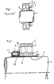
- FIG. 1 shows by way of a cross-sectional view a shaft 1 on which is mounted a double row spherical roller bearing 2 in accordance with known constructions such as described above.
- the shaft 1 is cylindrical and the bearing 2 has a tapered bore.
- the mounting of the bearing on the shaft is effected with the aid of a conventional adapter sleeve 3, having a cylindrical bore and a tapering envelope surface.
- the adapter sleeve 3 also has a nut 4 with a locking washer 5.
- the nut 4 can be moved axially on the sleeve 3 by cooperating with an external thread provided on the end portion of the sleeve.
- the nut is thus able to push up the bearing on the taper sleeve portion by tightening of the nut 4 on the adapter sleeve.
- This mounting, and also a subsequent dismounting can be accomplished in a rather simple manner, but the force for turning the nut, as stated in the introductory part of the application, is rather high thereby making it difficult to obtain exactly the desired residual clearance in the bearing.
- Fig. 2 shows, on a slightly enlarged scale, a cross-sectional view of a bearing assembly in accordance with the present invention, with only the upper half of the shaft 1 and the bearing 2 being illustrated.
- the bearing 2 includes an inner race ring 6 and an outer race ring 6'.
- a sleeve 7 is positioned between the inner surface of the bore in the inner bearing 6 and the outer surface of the shaft 1.
- the bore of the inner race ring 6 of the bearing 2 and the outer envelope surface of the sleeve 7 are both provided with complementary saw-tooth shaped longitudinal profiles 8 that define complementary tapered surfaces for ascertaining a small radial extension of the clamping surfaces.
- the sleeve 7 is preferably provided with a longitudinally extending slot extending over its entire axial extent for ascertaining good radial deformability.
- the sleeve 7 is further provided with a flange member 9.
- the flange member 9 is mounted in a groove 10 in the sleeve 7 so that the flange member 9 is axially arrested or fixed relative to the sleeve 7.
- the flange member 9 has a plurality of evenly spaced apart and axially extending threaded through-holes which are each adapted to receive a respective pushing member in the form of a set screw 11.
- the front end of each set screw 11 is directed towards the bearing 2 and acts when tightened, preferably via the intermediary of a thrust washer 12, against the side face of the inner ring 6 of the bearing.
- the axially movable thrust washer 12 is positioned between the end face of the inner race ring 6 and the facing end of the flange member 9 that faces the bearing 2 and is designed to evenly distribute the pushing up force to the inner race ring 6.
- the number of set screws used in the flange member 7 shown in Fig. 2 is preferably at least two, with such screws being generally equally spaced apart. However, to obtain an even and uniform pressure against the inner race ring, it is preferable to use three or four such set screws 11 evenly distributed or spaced around the flange member.
- Fig. 3 illustrates a set of three screws 11 each threadably received in a respective through hole in the flange member 9 and equally spaced apart from one another.
- a major advantage associated with the present invention is that the required axial driving up force for correcting the inner radial clearance in the bearing is achieved by the choice of an appropriate number of the set screws 11 used in relation to the size of the bearing to be mounted and then tightening these set screws to a maximum. It is thus not necessary to control the clearance in the typical manner, e.g. with aid of a measuring device. Furthermore such measuring devices cannot be used with scaled bearings where it is not possible to gain access to the interior of the bearing.
- the taper of a conventional adapter sleeve is most often 1:12, and the main reason for this is that it is geometrically difficult to design the adaptor sleeve with a steeper taper angle.
- a steeper taper angle is however preferable for the following reasons:
- a taper of between about 1:3 and 1:3.5 which is close to self-braking, gives a good mounting and dismounting result with a considerably reduced force required for driving up.
- the taper of the bore in the inner race ring 6 and the taper of the outer envelope surface of the sleeve member 7 in accordance with the present invention is between 1:3 and 1:3.5.
- the bearing assembly can also be designed for easy dismounting of the bearing, in which case a similar flange member as that shown in Fig. 2 can be arranged on a portion of the sleeve projecting out from the opposite side face of the bearing.
- Fig. 4 illustrates such an arrangement and shows a second flange member 9' mounted in a groove in the sleeve 7 so that the second flange member 9' is axially arrested or fixed relative to the sleeve 7.
- the second flange member 9' is provided with threaded through holes that each receive a respective set screw 11'.
- This second set of set screws 11' is arranged to act, preferably via the intermediary of a second thrust washer 12', on the opposite side face of the bearing.
- Fig. 4 also illustrates that a seal element 20 can be positioned between the flange member 9 and the thrust washer 12 adjacent the radially outer region of the flange member 9 and the thrust washer 12.
- a seal element 22 can also be positioned between the second flange member 9' and the second thrust washer 12' adjacent the radially inner region of the second flange member 9' and the second thrust washer 12'.
- These seal elements 20, 22 can be used to provide sealing characteristics depending upon the environment in which the rolling bearing is employed.
- the seal element 20 shown in fig. 4 can be used in connection with the arrangement depicted in Fig. 2.
- the mounting of the rolling bearing 2 on the shaft 1 can be effected by positioning the rolling bearing 2 on the shaft 7 with the sleeve member 7 being interposed between the inner race ring 6 of the rolling bearing 2 and an outer peripheral surface of the shaft 1.
- the pushing members move axially towards the inner race ring 6 and apply an axial force to the inner race ring 6 which forces the taper surface of the bore in the inner race ring 6 to move up the tapered envelope surface of the sleeve member 7 to thereby produce an interference fit.
- the pushing members 11' move axially towards the inner race ring 6 and apply an axial force to the inner race ring 6 which forces the taper surface of the bore in the inner race ring 6 to move down the tapered envelope surface of the sleeve member 7 to thereby effect dismounting.
Landscapes
- Engineering & Computer Science (AREA)
- General Engineering & Computer Science (AREA)
- Mechanical Engineering (AREA)
- Mounting Of Bearings Or Others (AREA)
- Support Of The Bearing (AREA)
Applications Claiming Priority (2)
| Application Number | Priority Date | Filing Date | Title |
|---|---|---|---|
| US99217397A | 1997-12-17 | 1997-12-17 | |
| US992173 | 1997-12-17 |
Publications (2)
| Publication Number | Publication Date |
|---|---|
| EP0926370A2 true EP0926370A2 (de) | 1999-06-30 |
| EP0926370A3 EP0926370A3 (de) | 2000-07-26 |
Family
ID=25538005
Family Applications (1)
| Application Number | Title | Priority Date | Filing Date |
|---|---|---|---|
| EP98850193A Withdrawn EP0926370A3 (de) | 1997-12-17 | 1998-12-14 | Vorrichtung zur Montage eines Lagers auf eine Welle |
Country Status (3)
| Country | Link |
|---|---|
| EP (1) | EP0926370A3 (de) |
| JP (1) | JPH11247872A (de) |
| CN (1) | CN1220354A (de) |
Cited By (6)
| Publication number | Priority date | Publication date | Assignee | Title |
|---|---|---|---|---|
| EP1314904A1 (de) * | 2001-11-16 | 2003-05-28 | Aktiebolaget SKF | Verfahren zum Befestigen einer Hülse auf einer Welle und Hülsenvorrichtung für solch eine Befestigung |
| WO2008076011A1 (en) * | 2006-12-20 | 2008-06-26 | Aktiebolaget Skf | A spherical roller bearing with integrated locking device |
| WO2009113939A1 (en) * | 2008-03-12 | 2009-09-17 | Aktiebolaget Skf | A mounting sleeve for mounting a ring member on a shaft and a bearing assembly incorporating such a mounting sleeve |
| CN105090454A (zh) * | 2015-08-08 | 2015-11-25 | 常州市武进金城齿轮有限公司 | 齿轮轴向固定装置 |
| CN106979247A (zh) * | 2017-05-16 | 2017-07-25 | 响水县贝斯特传动件有限公司 | 一种机械类滚动轴承的h型紧定套 |
| CN112805481A (zh) * | 2018-10-31 | 2021-05-14 | 舍弗勒技术股份两合公司 | 预张紧的滚动元件安装 |
Families Citing this family (5)
| Publication number | Priority date | Publication date | Assignee | Title |
|---|---|---|---|---|
| JP4757436B2 (ja) * | 2003-10-02 | 2011-08-24 | 住友重機械工業株式会社 | 軸の心出し方法 |
| US7344313B2 (en) * | 2004-05-19 | 2008-03-18 | Qm Holdings Ltd. | Taper lock bearing assembly |
| CN102717101A (zh) * | 2011-03-31 | 2012-10-10 | 湖北汇科数控组合机电装备有限公司 | 铣削头、镗削头主轴 |
| CN105114474B (zh) * | 2015-08-28 | 2018-05-04 | 郑州飞机装备有限责任公司 | 具备辅助轴承拆卸功能的轴承体 |
| CN106763229A (zh) * | 2017-01-05 | 2017-05-31 | 武汉船用机械有限责任公司 | 一种锥套轴承的预紧装置及方法 |
Family Cites Families (3)
| Publication number | Priority date | Publication date | Assignee | Title |
|---|---|---|---|---|
| SE442430B (sv) * | 1982-05-17 | 1985-12-23 | Skf Nova Ab | Anordning for montering av ett maskinelement pa en axel |
| SE450851B (sv) * | 1986-01-24 | 1987-08-03 | Skf Mekanprodukter Ab | Anordning for montering av ett lager innefattande tetningar |
| SE461803B (sv) * | 1989-03-17 | 1990-03-26 | Skf Mekanprodukter Ab | Anordning foer montering av ett lager paa en axel |
-
1998
- 1998-12-14 EP EP98850193A patent/EP0926370A3/de not_active Withdrawn
- 1998-12-16 JP JP10357306A patent/JPH11247872A/ja active Pending
- 1998-12-17 CN CN98125574A patent/CN1220354A/zh active Pending
Non-Patent Citations (1)
| Title |
|---|
| None |
Cited By (9)
| Publication number | Priority date | Publication date | Assignee | Title |
|---|---|---|---|---|
| EP1314904A1 (de) * | 2001-11-16 | 2003-05-28 | Aktiebolaget SKF | Verfahren zum Befestigen einer Hülse auf einer Welle und Hülsenvorrichtung für solch eine Befestigung |
| US7037026B2 (en) | 2001-11-16 | 2006-05-02 | Ab Skf | Method for mounting a sleeve on a shaft and a sleeve device for such mounting |
| WO2008076011A1 (en) * | 2006-12-20 | 2008-06-26 | Aktiebolaget Skf | A spherical roller bearing with integrated locking device |
| WO2009113939A1 (en) * | 2008-03-12 | 2009-09-17 | Aktiebolaget Skf | A mounting sleeve for mounting a ring member on a shaft and a bearing assembly incorporating such a mounting sleeve |
| US8801293B2 (en) | 2008-03-12 | 2014-08-12 | Aktiebolaget Skf | Mounting sleeve for mounting a ring member on a shaft and a bearing assembly incorporating such a mounting sleeve |
| CN105090454A (zh) * | 2015-08-08 | 2015-11-25 | 常州市武进金城齿轮有限公司 | 齿轮轴向固定装置 |
| CN106979247A (zh) * | 2017-05-16 | 2017-07-25 | 响水县贝斯特传动件有限公司 | 一种机械类滚动轴承的h型紧定套 |
| CN112805481A (zh) * | 2018-10-31 | 2021-05-14 | 舍弗勒技术股份两合公司 | 预张紧的滚动元件安装 |
| US11585382B2 (en) | 2018-10-31 | 2023-02-21 | Schaeffler Technologies AG & Co. KG | Pre-tensioned rolling element mounting |
Also Published As
| Publication number | Publication date |
|---|---|
| JPH11247872A (ja) | 1999-09-14 |
| CN1220354A (zh) | 1999-06-23 |
| EP0926370A3 (de) | 2000-07-26 |
Similar Documents
| Publication | Publication Date | Title |
|---|---|---|
| US5709483A (en) | Bearing assembly utilizing improved clamping arrangement | |
| US7344313B2 (en) | Taper lock bearing assembly | |
| EP0967404B1 (de) | Vorrichtung zur Montage einer Lagereinheit | |
| GB2120360A (en) | Device for mounting a machine element on a shaft | |
| US5330284A (en) | Apparatus for mounting and dismounting bearings | |
| US4804233A (en) | Double-row anti-friction bearing, particulary for wheels of automotive vehicles | |
| JPS63172010A (ja) | 転がり軸受 | |
| JPH11247872A (ja) | 軸受装置及び軸受の組込み取外し方法 | |
| US6893160B2 (en) | Bearing assembly | |
| US5524988A (en) | Rotary apparatus with gap-controlling | |
| JP3855304B2 (ja) | クロスローラ軸受の予圧調整構造 | |
| JP3068385U (ja) | 軸受装置 | |
| US6312162B1 (en) | Adjustable bearing spacer | |
| US5174661A (en) | Device for mounting a rotating part between two bearings without play | |
| US5795119A (en) | Adjustable lock nut | |
| US4235573A (en) | Double acting hub-to-shaft clamp connection | |
| US2811861A (en) | Adapter coupling means | |
| GB2167834A (en) | Means for securing a bearing to a shaft | |
| US3580648A (en) | Roll and antifriction bearing assembly | |
| US6220820B1 (en) | Bearing preload | |
| US5111575A (en) | Swaging tool for bearing installation | |
| WO2008076011A1 (en) | A spherical roller bearing with integrated locking device | |
| US7147380B2 (en) | Pressure screw assembly primarily used with an axially guided locking ring to permit controlled axial clearance movement of the chock bearing | |
| US5634753A (en) | Adjustable lock nut | |
| KR102968906B1 (ko) | 휠 베어링 조립체 및 그 조립방법 |
Legal Events
| Date | Code | Title | Description |
|---|---|---|---|
| PUAI | Public reference made under article 153(3) epc to a published international application that has entered the european phase |
Free format text: ORIGINAL CODE: 0009012 |
|
| AK | Designated contracting states |
Kind code of ref document: A2 Designated state(s): AT BE CH CY DE DK ES FI FR GB GR IE IT LI LU MC NL PT SE |
|
| AX | Request for extension of the european patent |
Free format text: AL;LT;LV;MK;RO;SI |
|
| PUAL | Search report despatched |
Free format text: ORIGINAL CODE: 0009013 |
|
| STAA | Information on the status of an ep patent application or granted ep patent |
Free format text: STATUS: THE APPLICATION HAS BEEN WITHDRAWN |
|
| AK | Designated contracting states |
Kind code of ref document: A3 Designated state(s): AT BE CH CY DE DK ES FI FR GB GR IE IT LI LU MC NL PT SE |
|
| AX | Request for extension of the european patent |
Free format text: AL;LT;LV;MK;RO;SI |
|
| 18W | Application withdrawn |
Withdrawal date: 20000622 |