EP0926404B1 - Steuerventilsystem für ein mehrgängiges Automatikgetriebe - Google Patents
Steuerventilsystem für ein mehrgängiges Automatikgetriebe Download PDFInfo
- Publication number
- EP0926404B1 EP0926404B1 EP98310408A EP98310408A EP0926404B1 EP 0926404 B1 EP0926404 B1 EP 0926404B1 EP 98310408 A EP98310408 A EP 98310408A EP 98310408 A EP98310408 A EP 98310408A EP 0926404 B1 EP0926404 B1 EP 0926404B1
- Authority
- EP
- European Patent Office
- Prior art keywords
- pressure
- brake
- clutch
- high clutch
- torque
- Prior art date
- Legal status (The legal status is an assumption and is not a legal conclusion. Google has not performed a legal analysis and makes no representation as to the accuracy of the status listed.)
- Expired - Lifetime
Links
- 230000005540 biological transmission Effects 0.000 title claims description 71
- 238000006243 chemical reaction Methods 0.000 claims description 42
- 239000012530 fluid Substances 0.000 claims description 9
- 238000012544 monitoring process Methods 0.000 claims description 4
- 238000004873 anchoring Methods 0.000 claims description 3
- 230000001360 synchronised effect Effects 0.000 description 20
- 238000010586 diagram Methods 0.000 description 19
- 238000009825 accumulation Methods 0.000 description 17
- 230000008859 change Effects 0.000 description 16
- 230000008878 coupling Effects 0.000 description 15
- 238000010168 coupling process Methods 0.000 description 15
- 238000005859 coupling reaction Methods 0.000 description 15
- 102100031948 Enhancer of polycomb homolog 1 Human genes 0.000 description 11
- 101000920634 Homo sapiens Enhancer of polycomb homolog 1 Proteins 0.000 description 11
- 230000006870 function Effects 0.000 description 10
- 230000000694 effects Effects 0.000 description 7
- 238000004364 calculation method Methods 0.000 description 6
- 230000002441 reversible effect Effects 0.000 description 6
- 230000001143 conditioned effect Effects 0.000 description 5
- 230000007704 transition Effects 0.000 description 5
- 230000003247 decreasing effect Effects 0.000 description 4
- 238000012795 verification Methods 0.000 description 4
- 239000008186 active pharmaceutical agent Substances 0.000 description 3
- 238000013461 design Methods 0.000 description 3
- 230000001970 hydrokinetic effect Effects 0.000 description 3
- 230000006872 improvement Effects 0.000 description 3
- 230000000977 initiatory effect Effects 0.000 description 3
- 230000002829 reductive effect Effects 0.000 description 3
- 230000001960 triggered effect Effects 0.000 description 3
- 230000009471 action Effects 0.000 description 2
- 230000003321 amplification Effects 0.000 description 2
- 238000000034 method Methods 0.000 description 2
- 238000003199 nucleic acid amplification method Methods 0.000 description 2
- 230000009467 reduction Effects 0.000 description 2
- 230000003068 static effect Effects 0.000 description 2
- 238000012546 transfer Methods 0.000 description 2
- 230000006978 adaptation Effects 0.000 description 1
- 230000008901 benefit Effects 0.000 description 1
- 238000004891 communication Methods 0.000 description 1
- 238000011217 control strategy Methods 0.000 description 1
- 238000013270 controlled release Methods 0.000 description 1
- 239000002826 coolant Substances 0.000 description 1
- 230000007423 decrease Effects 0.000 description 1
- 230000000593 degrading effect Effects 0.000 description 1
- 230000001419 dependent effect Effects 0.000 description 1
- 230000008030 elimination Effects 0.000 description 1
- 238000003379 elimination reaction Methods 0.000 description 1
- 230000002708 enhancing effect Effects 0.000 description 1
- 238000005429 filling process Methods 0.000 description 1
- 230000036961 partial effect Effects 0.000 description 1
- 238000012545 processing Methods 0.000 description 1
- 230000004044 response Effects 0.000 description 1
- 239000013589 supplement Substances 0.000 description 1
Images












Classifications
-
- F—MECHANICAL ENGINEERING; LIGHTING; HEATING; WEAPONS; BLASTING
- F16—ENGINEERING ELEMENTS AND UNITS; GENERAL MEASURES FOR PRODUCING AND MAINTAINING EFFECTIVE FUNCTIONING OF MACHINES OR INSTALLATIONS; THERMAL INSULATION IN GENERAL
- F16H—GEARING
- F16H61/00—Control functions within control units of change-speed- or reversing-gearings for conveying rotary motion ; Control of exclusively fluid gearing, friction gearing, gearings with endless flexible members or other particular types of gearing
- F16H61/04—Smoothing ratio shift
- F16H61/06—Smoothing ratio shift by controlling rate of change of fluid pressure
- F16H61/061—Smoothing ratio shift by controlling rate of change of fluid pressure using electric control means
-
- F—MECHANICAL ENGINEERING; LIGHTING; HEATING; WEAPONS; BLASTING
- F16—ENGINEERING ELEMENTS AND UNITS; GENERAL MEASURES FOR PRODUCING AND MAINTAINING EFFECTIVE FUNCTIONING OF MACHINES OR INSTALLATIONS; THERMAL INSULATION IN GENERAL
- F16H—GEARING
- F16H61/00—Control functions within control units of change-speed- or reversing-gearings for conveying rotary motion ; Control of exclusively fluid gearing, friction gearing, gearings with endless flexible members or other particular types of gearing
- F16H2061/0075—Control functions within control units of change-speed- or reversing-gearings for conveying rotary motion ; Control of exclusively fluid gearing, friction gearing, gearings with endless flexible members or other particular types of gearing characterised by a particular control method
- F16H2061/0078—Linear control, e.g. PID, state feedback or Kalman
-
- F—MECHANICAL ENGINEERING; LIGHTING; HEATING; WEAPONS; BLASTING
- F16—ENGINEERING ELEMENTS AND UNITS; GENERAL MEASURES FOR PRODUCING AND MAINTAINING EFFECTIVE FUNCTIONING OF MACHINES OR INSTALLATIONS; THERMAL INSULATION IN GENERAL
- F16H—GEARING
- F16H61/00—Control functions within control units of change-speed- or reversing-gearings for conveying rotary motion ; Control of exclusively fluid gearing, friction gearing, gearings with endless flexible members or other particular types of gearing
- F16H61/04—Smoothing ratio shift
- F16H2061/0466—Smoothing shift shock by apply or release of band brake servos, e.g. overlap control of band brake and a clutch or vice versa
Definitions
- the invention relates to multiple ratio automatic transmissions for automotive vehicles comprising electronically controlled valve systems for controlling ratio changes.
- the transmission of the preferred embodiment of the present invention includes a three speed ratio gear system commonly referred to as a Simpson gear set, and a two speed ratio simple planetary gear unit arranged in series.
- the gearing of the transmission of the present invention has features that are common to the gearing arrangement of U.S. Patent No. 5,586,029, which has four forward driving speed ratios and a single reverse speed ratio.
- a five speed ratio version of the gearing of U.S. Patent No. 5,586,029, is described in U.S. Patent No. 5,642,283. Reference is made to these patents to supplement the disclosure of the present invention.
- the simple planetary gear unit of the '283 patent is used to establish an additional ratio having a numerical value that is greater than the lowest ratio of the four speed gearing of U.S. Patent No. 5,586,029, but which is less than the second ratio of the gearing of the U.S. patent No. 5,586,029,.
- a transition from the second ratio to the third ratio of the present transmission involves a swapping or interchanging of reaction elements for the simple planetary gear unit and for the Simpson gear unit.
- the additional ratio converts the four speed gearing of the transmission of the '029 patent into a five speed ratio transmission.
- Ratio changes in the five speed ratio version of the transmission may be controlled by a control valve system of the kind disclosed in U.S. Patent No. 5,646,842.
- the transition between second and third gear ratio involves the simultaneous engagement of the drive clutch and the disengagement of the reaction brake, which is referred to as a synchronous reaction-to-drive shift.
- the 3-2 downshift is the reverse of a 2-3 shift and is referred to as a synchronous drive-to-reaction shift.
- a non-synchronous adaptation of a gearing arrangement of the kind shown in the preceding patents would include an overrunning coupling and a friction brake for establishing a reaction point for the common sun gear of the Simpson gear set and a separate overrunning coupling for clutching together two elements of the simple planetary gear unit.
- An upshift from the third ratio to the fourth ratio and a downshift from the fourth ratio to the third ratio, as well as a downshift from the fifth ratio to the third ratio in the non-synchronous version of the gearing require the use of two overrunning couplings and the engagement or release of only a single friction element.
- the control of these ratio shifts requires the engagement and release of the reaction brake or clutch on upshifts and downshifts.
- a single variable force solenoid is used to establish the reaction brake pressure for the Simpson gear set reaction point as well as the reaction brake pressure for the simple planetary gear unit.
- a friction clutch which is used to establish a third speed ratio, has its pressure controlled by the same variable force solenoid.
- the clutch that is used for third (fourth in 5-speed version) speed ratio operation is the same clutch that is used for reverse operation. Thus the capacity of the clutch must be established at a high level. Because of the driveline torque requirements for reverse, that torque level is greater than the torque level that is needed for establishing a reaction point for third (fourth in 5-speed version) speed ratio operation.
- EP-A-0798495 discloses a multiple ratio automatic transmission forming plural torque flow paths from an engine to a torque output shaft; comprising planetary gear elements including a sun gear, a ring gear and a planetary carrier assembly defining said torque flow paths; a high ratio clutch means for connecting together two of said gear elements for rotation in unison, thereby establishing a high ratio, the clutch means including a high ratio clutch servo having a clutch apply pressure chamber; an underdrive brake means for anchoring one of said gear elements thereby establishing an underdrive ratio, the underdrive brake means including an underdrive brake servo having a brake apply pressure chamber and a brake release pressure chamber separated from one another by a movable brake actuator and a control valve system having an engine driven control pressure pump, a first solenoid operated valve means for controlling pressure in said brake apply pressure chamber, and a second solenoid operated valve means for controlling pressure in said brake release pressure chamber and in said clutch apply pressure chamber, said first solenoid operated valve
- an automatic transmission as taught by EP-A-0798495 which is characterized by a first modulator valve means defining in part a fluid connection between said first solenoid operated valve means for modifying the rate of pressure build-up in said intermediate servo brake apply pressure chamber and a second modulator valve means defining in part a fluid connection between said second solenoid operated valve means and both said high ratio clutch apply pressure chamber and said underdrive brake release pressure chamber for modifying the rate of pressure build-up in said high ratio clutch apply pressure chamber and said underdrive brake release pressure chamber thereby enabling variation in the duration and in the torque characteristic for the inertia phase of the ratio upshift.
- the shift control system in the present invention provides improved quality of upshifts from the third ratio to the fourth ratio as well as downshifts from the fourth ratio to the third ratio and from the fifth ratio to the third ratio in a gearing arrangement of the type shown in U.S. Patent No. 5,642,283. This is accomplished by enabling the high clutch to be controlled independently of the torque transmission requirements of the intermediate servo.
- the intermediate servo thus has its own variable force solenoid that can be calibrated separately, depending upon the torque requirements of the intermediate servo.
- the variable force solenoid for the high clutch is used to control the flow of fluid to and from the high clutch during ratio changes.
- the variable force solenoid that controls the intermediate servo is used to control intermediate servo pressure during ratio changes.
- a second brake that is involved in a downshift from the fifth ratio to the third ratio is similar'to the brake that is involved in a downshift from the fourth ratio to the third ratio and is released synchronously with respect to the first brake.
- the transmission of the present invention includes a simple planetary gear unit and a Simpson-type gear unit as disclosed in U.S. Patent No. 5,642,283, for example, as well as the other patents identified in the preceding discussion.
- the Simpson gear set and the overdrive planetary gear unit are arranged in series, the overdrive gear unit being disposed between a hydrokinetic torque converter and the torque input element of the Simpson gear set.
- the intermediate ratio brake B2 of the present invention which is applied during third speed ratio operation, is a band brake which anchors a common sun gear for the Simpson gear set.
- the reaction brake for the simple planetary gear unit is applied during second ratio operation, but is released during third speed ratio operation.
- the brake B2 is released and a friction clutch C2 is applied, which establishes a direct drive ratio through the Simpson gear set.
- the 3-4 upshift and the 4-3 downshift are synchronous shifts.
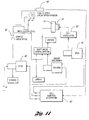
- Figure 11 shows the overall control system for the driveline including the engine, the processor, the transmission and the signals developed by the driver, the engine and the transmission that are used by the processor. These signals interact, one with respect to the other.
- the driver signals are identified in Figure 11 as OCS and TP signals.
- the transmission sensors are identified by the symbols VSS, TSS, MLP, TOT, OSS, and HCDSS.
- the engine signals are identified by the symbols N, MAF, and ECT.
- the symbol OCS refers to the overdrive cancel switch.
- the symbol TP refers to the throttle position.
- VSS refers to the vehicle speed sensor at the output shaft of the transmission.
- TSS refers to the turbine speed sensor at the input shaft of the transmission.
- MLP refers to the manual level position at the transmission, which selects the drive range.
- OSS refers to output shaft speed sensor and the term HCDS refers to high clutch drum speed.
- the engine sensors monitor RPM, which is the engine speed; MAF, which is the mass air flow; and ECT, which is the engine coolant temperature.
- the control system includes two ON/OFF solenoids identified in the schematic drawings as SS1 and SS2. These control ratio shifts. It has one variable force solenoid for controlling B2 brake capacity, which is identified in the drawings as VFS1. A separate variable force solenoid, identified as VFS3, varies the capacity for the clutch C2 which, when applied, locks up the Simpson gear set for 1:1 ratio operation.
- VFS1 variable force solenoid
- the foregoing signals are used by shift modulator valves to actuate shift valves that in turn release and apply hydraulic pressure to the torque transmitting elements B1 and C2.
- the modulator valves adjust the amount of the clutch capacity applied to the friction elements.
- Figure 12 shows in schematic form the torque flow path for the transmission gearing. It includes a Simpson gear set 10 and a simple planetary overdrive gear unit 12.
- Simpson gear set 10 has two simple planetary gear units 14 and 16 with a common sun gear 18.
- the carrier of unit 14 and the ring gear of gear unit 16 are connected to torque output shaft 20.
- the carrier of gear unit 16 is anchored against rotation in one direction by an overrunning coupling identified as OWC2 during operation in the first ratio.
- Brake B3 shown in Figure 11 would be anchored if coast braking is desired.
- Sun gear 18 of the Simpson gear set is adapted to be anchored by brake B2.
- Forward drive clutch C3 provides input torque to the ring gear of the planetary gear unit 14. During operation in each forward driving ratio, clutch C3 is adapted to distribute torque from the torque input shaft 22 to the common sun gear 18 for the Simpson gear set.
- the simple planetary gear unit 12 has a ring gear which is coupled by OWC1 to the carrier of the gear unit 12 during operation whenever brake band B1 is released.
- Brake band B1 anchors the sun gear of the gear unit 12 to provide an overdrive mode for the gear unit 12.
- a coast clutch C1 is used when coast braking is desired since the overrunning coupling OWC1 cannot deliver torque in both directions.
- the engine crankshaft is connected to shaft 24, which drives the impeller of the impeller 26 of the hydrokinetic torque converter.
- the turbine 28 of the hydrokinetic torque converter delivers torque to the input shaft 22.
- clutch C3 During operation in each forward driving ratio, clutch C3 is applied.
- overrunning coupling OWC1 In the first driving ratio, overrunning coupling OWC1 is engaged so that turbine torque is delivered through clutch C3 to the ring gear of gear unit 14 for the Simpson gear set.
- Reaction torque for the Simpson gear set is distributed to the transmission case through coupling OWC2 during first ratio operation.
- brake B1 On a ratio change from the first ratio to the second ratio, brake B1 is applied. This releases the coupling OWC1 as the sun gear for gear unit 12 is anchored. Turbine torque then is delivered through the planetary gear unit 12 with a reduced torque multiplication.
- the carrier for gear unit 16 continues to act as a reaction point during second ratio operation.
- brake band B1 is released and brake band B2 is applied. This overspeeds ring gear 14 relative to the sun gear 18 of the Simpson gear set and the overrunning coupling OWC1 reapplies, thus establishing a 1:1 ratio in the gear unit 12.
- a ratio change from the third ratio to the fourth ratio involves disengaging brake B2 and applying clutch C2. This locks up the Simpson gear set for unitary ratio operation. Simultaneously, the planetary gear unit 12 becomes locked up for unitary ratio operation by the overrunning coupling OWC1.
- the torque flow through the transmission shown in Figure 10 is the same as that previously described with reference to Figure 12.
- a friction brake C4 and an overrunning coupling OWC3 are added to provide a reaction point for the sun gear 18' of the Simpson gear set 10'.
- the overrunning coupling OWC3 functions in the same manner as brake B2 of the transmission shown in Figure 12, although it is capable of accommodating torque transfer in one direction only.
- Brake B2 in the embodiment of Figure 10 is used for coast braking purposes.
- a 3-4 upshift in the case of the transmission of Figure 10 is accomplished in a non-synchronous manner.
- clutch C4 remains applied, the overrunning coupling OWC3 overruns when the ratio change to the fourth ratio is commanded. This does not involve a release of a brake and the application of a friction clutch as in the case of the transmission of Figure 12 where brake B2 is released and clutch C2 is applied on a 3-4 upshift and where clutch C2 is released and brake B2 is applied on a 4-3 downshift or on a 5-3 downshift.
- the improved control system of the present invention eliminates the need for providing an intermediate clutch C4 and an intermediate one-way clutch OWC3. It does this by establishing electronically controlled synchronization of 3-4 upshifts, 4-3 downshifts, and 5-3 downshifts which are synchronized by the engagement of the intermediate band B2 and the high clutch C2.
- the electronic-mechanical interface for the 3-4, 4-3 and 5-3 shift control system requires only two of the three ON/OFF solenoids and two of the three variable force solenoids in order to execute the shifts.
- the ON/OFF solenoids are required to activate or terminate the capacity control on brake B2 and clutch C2 by applying or controlling or exhausting the clutch and band pressures.
- a shift valve configuration activated by the two affected ON/OFF solenoids is used to apply or release the clutch and brake band pressures.
- VFS3 is used for capacity control of clutch C2 and variable force solenoid VFS1 is used for control of the capacity of brake B2.
- VFS1 is used for capacity control of clutch C2
- VFS1 is used for control of the capacity of brake B2.
- the control system for the present transmission uses a high clutch drum speed sensor (HCDS) rather than an overdrive drum speed sensor.
- HCDS high clutch drum speed sensor
- the high clutch drum speed sensor determines the speed of the high clutch drum C2.
- the high clutch drum speed sensor HCDS is a variable reluctance sensor in which the signal pulses are established by teeth on the high clutch drum as the teeth pass through the magnetic field established by the sensor. Since the high clutch drum is connected to the common sun gear of the Simpson gear unit, the high clutch drum speed sensor monitors the sun gear speed.
- the 3-4 upshift and the 4-3 and 5-3 downshifts are synchronous shifts.
- the following chart provides a summary of the elements that are involved in these shifts. Shifts 5-Speed Transmission 3-4 Reaction to Drive (B2 to C2) 4-3 Drive to Reaction (C2 to B2) 5-3 Drive/Reaction to Reaction (C2/B1 to B2)
- the synchronous 3-4 upshift is a synchronous reaction to drive shift.
- the reaction element is the intermediate brake band B2 and the drive element is the high clutch C2.
- the 3-4 upshift corresponds to a 2-3 upshift in the four-speed transmission of Patent No. 5,646,842.
- Figure 1 shows the shift dynamics of a 2-3 upshift for a transmission of the kind shown in Patent No. 5,646,842. An understanding of this upshift is necessary in order to understand the dynamics of a 3-4 upshift for the present transmission.
- the high clutch is fed with pressurized fluid through the shift valve configuration, which is supplied with line pressure through a control orifice.
- the intermediate servo B2 is supplied with line pressure on its release side A1 by the shift valve configuration.
- the apply side of the servo A2 is supplied with CF pressure from a pressure modulator valve which, in turn, is in communication with a variable force solenoid (VFS1).
- VFS1 variable force solenoid
- the capacity of the high clutch C2 is established to provide sufficient braking capacity for reverse drive.
- the high clutch in this case is subjected to full input shaft torque.
- the high clutch In third gear or during a 2-3 upshift, the high clutch carries only a fraction of the input shaft torque depending upon the gear ratio as the high clutch has excess capacity for a 2-3 upshift.
- the intermediate servo B2 stroke volume is used to establish an accumulator effect for the high clutch C2.
- Figure 6 shows the variation, during the 4-3/5-3 downshift interval, of the turbine speed, the output shaft torque, B2 torque, and high clutch pressure.
- the intermediate servo has differential areas at A1 and A2, the release side having the larger area A1.
- An intermediate servo return spring acts to stroke the servo piston to its release position.
- the servo release side is applied with line pressure and the servo apply side is connected to a clutch pressure modulating device, thereby subjecting it to CF pressure.
- the stroking of the intermediate servo piston establishes the accumulator effect for the high clutch during a 2-3 upshift.
- phase 3 of the 2-3 upshift shown in Figure 1, the high clutch is synchronized with respect to the intermediate band.
- the pressure applied on the high clutch pressurizes the friction plates and the high clutch starts to transmit torque.
- the high clutch pressure rises and decreases the reaction torque on the intermediate brake band B2 since the high clutch pressure is also applied on the release side area A1 of the intermediate servo.
- the intermediate servo begins to stroke and the high clutch transmits full torque.
- the output shaft torque characteristic changes at that point from a negative slope, representing a reaction torque reduction of the intermediate band, to a positive high clutch pressure or torque characteristic.
- phase 4 of the shift shown in Figure 1 pressure accumulation takes place.
- the system is provided with line pressure through the shift valve circuit.
- the load applied at the apply side A2 of the servo B2 determines the high clutch accumulation pressure.
- the CF pressure is electronically controlled. By changing the EPC pressure, the CF pressure is varied and this in turn changes the high clutch accumulation pressure and time.
- the accumulation time is determined by the size of the control orifice, which allows a metered flow to pass to the high clutch, and by the stroke distance of the intermediate servo.
- the source of pressurized fluid flow is line pressure. Accumulation time, however, is not consistent, especially at high pressure operation modes. The higher the servo size and the higher the high clutch pressure, the shorter is the accumulation time.
- the metering of the fluid by the control orifice usually is not sufficient enough to match the appropriate accumulation time to the required shift time.
- the inertia phase on the 2-3 upshift is executed.
- the high clutch pressure rises to the line pressure level.
- the remaining part of the shift will be executed with elevated line pressure, which results in uncomfortable shift harshness.
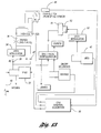
- the improved control system as a whole is shown in block diagram form in Figure 3.
- the upshift control system of Figures 3 and 13 has features that are common to the control system of the '842 patent.
- the major distinction is the presence of a variable force solenoid VFS3.
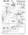
- This solenoid is shown at 32 in Figure 13. It acts conjunction with a VFS3 modulator valve 34, which applies pressure to the high clutch through control orifice 36. Pressure distributed from solenoid valve VFS3 takes place through orifice 38, seen in Figure 13. If orifice 38 is closed, pressure will be distributed through a second orifice 40, which bypasses the modulator valve 34 as pressure is distributed to the high clutch through the orifice 36.
- variable force solenoid VFS3 is line pressure, as seen at 40, which enables the variable force solenoid VFS3 at 32 to distribute controlled flow rates to the high clutch C2 and the intermediate servo release side B2 during 3-4 upshifts.
- the controlled flow rates entering the intermediate servo release side and the high clutch circuit will guarantee consistent accumulation times (see phase 4 of Figure 1) regardless of the operation mode of the transmission and regardless of piston servo sizes.
- the complete high clutch pressure characteristic can be controlled electronically during the torque phase and the inertia phase of a 3-4 upshift.
- the slope of the torque phase for this shift can be adjusted depending on the flow rate released from the variable force solenoid 32 into the high clutch and intermediate servo release circuit.
- the flow rate will determine the flatness or the steepness of the high clutch torque. This influences the duration of the pressure build-up, the steepness and the flatness.
- the torque phase, the transition from the torque phase to the inertia phase, and the inertia phase itself can be adjusted by using this additional calibration tool.
- the torque phase characteristics and the accumulation time can be matched to individual 3-4 upshift requirements, thus enhancing the 3-4 upshift quality.
- Figure 2 shows this function in graphic form during the shift interval from t1 to t2 to t 3 . That is, the pressure on the clutch C2 can be varied as well as the torque of the intermediate servo B2 as the slope of the C2 pressure is changed between pressure slope 2 and pressure slope 1 shown in Figure 2.
- the high clutch begins to engage, thereby reducing the reaction torque of the intermediate brake band.
- the initiation of the pressure slope 2 for the high flow rate at variable force solenoid 32 or at the modulator valve 34 begins to increase.
- the reaction torque at B2 is reduced.
- the output shaft torque signature follows the sum of the negative torque reaction at B2 and the positive high clutch torque at C2.
- the reaction torque slope generated by the high clutch pressure slope 2 is more flat.
- the duration of the torque phase is increased and the changeover from the torque phase to the inertia phase is smooth due to the flat high clutch pressure increase that is controlled by the lowered flow rate of the variable force solenoid 32 or the modulator valve 34.
- the accumulation time during a 3-4 upshift can be matched to all the required shift times by the flow control of the variable force solenoid (VFS3) shown at 32 and the pressure control of the variable force solenoid (VFS1) shown at 42.
- Accumulation time is independent of the stroke distance of the intermediate servo.
- the duration and the characteristic slope of the torque phase can be varied and adjusted to satisfy particular shift requirements.
- the initiation of the inertia phase of a 3-4 upshift can be adjusted by the pressure slope of the high clutch C2.
- the high clutch drum speed sensor is shown in Figures 3 and 13 at 44.
- the turbine speed sensor is shown in Figure 3 at 46 and the output shaft speed sensor is shown in Figure 3 at 48.
- the signal values from the transmission are distributed to a microprocessor controller 50, which has a central processing unit that calculates the derivative of the high clutch drum speed at 110.
- the central processor unit also uses control algorithms stored in memory to calculate a target value for the high clutch drum speed at 54.
- a commanded and desired gear also are calculated at 54, as are the clutch and brake band capacities.
- the derivative of the high clutch drum speed target value is calculated at 56, and a comparison is made between that calculated value and the actual high clutch drum speed determined at 52. If an error exists, a feedback circuit, which includes a proportional integral derivative (PID) controller, establishes feedback information for the variable force solenoids 32 and 42.
- PID proportional integral derivative
- the synchronous 4-3 downsh ft is a drive-to-reaction shift. That is the inverse of the 3-4 upshift previously described.
- the high clutch C2 is a drive member. It must have a controlled release in order to accomplish engagement of the intermediate band B2 as a reaction element at zero high clutch drum speed.
- This synchronization is required in order to avoid an engine overshoot or an engine speed flare-up as well as to provide good shift quality without sudden inertia torque disturbance.
- This synchronization on a 4-3 downshift requires a closed loop control release of the high clutch C2, independent control of the Lntermediate servo B2, and a monitoring of the high clutch drum speed.
- the 4-3 downshift requires also the gradual release of the high clutch in order to avoid large output shaft torque disturbances.
- Patent No. 5,646,842 has a synchronous 3-2 downshift and a synchronous 4-2 downshift.
- the control system thus has to synchronize the release of the high clutch and the application of the intermediate brake band.
- the synchronization point is at zero speed of the high clutch drum speed.
- the intermediate brake band must be applied simultaneously with the zero speed point.
- the pressure profile on the high clutch has to be controlled in order to minimize the output shaft torque disturbance. This is shown in Figure 4.
- the transmission of the '812 patent has two solenoid stages that effect intermediate steps between the third gear or fourth gear and the final second gear.
- Figure 5 shows the first and second intermediate steps on these downshifts. The difference in these two intermediate steps is the selection of two orifices that are controlled by the shift valve configuration.
- the Figures in the '842 patent that correspond to Figure 5 are Figures 25a and 25b.
- Figure 6 of the present invention corresponds to Figure 26 of the '842 patent.
- the two intermediate steps of Figure 5 are established with shift soLenoids SS1, SS2 and SS3 that form a part of the shift valve configuration.
- the intermediate servo apply pressure is controlled, as previously explained, by the clutch pressure modulator valve (forward) which produces CF pressure, as indicated in Figure 5.
- the pressure in the high clutch and the intermediate servo release circuit is exhaus:ed over the shift valve configuration through two different orifices, identified as holes 100 and 170.
- the intermediate servo pressure is relied upon to pressurize the oil against the high clutch piston to produce the distinct pressure profile on the high clutch that is indicated in Figure 6. That pressure profile is produced during the intermediate servo stroke phase and is entirely dependent upon CF1 pressure. That profile serves as an accumulator pressure for the high clutch as well as a synchronization tool for synchronizing both the clutch and the brake.
- the pressure profile is usually in the form of an electronic pressure control (EPC) ramp, which produces an equivalent pressure characteristic on the high clutch.
- EPC electronic pressure control
- the interdependence of the EPC pressure and the high clutch pressure is the result of the different amounts of metered oil developed by the different size orifices (holes 100 and 170), and the remaining oil flow is used to control the high clutch during the intermediate servo stroke phase.
- the pressure applied on the high clutch during a 3-2 downshift is required to hold the engine torque during the stroke phase of the intermediate servo.
- Two different size orifices are chosen in order to cover respectively the high speed shifts and low speed shifts on a 3-2 downshift.
- the intermediate steps can be selected individually or both in series if that is required.
- Figure 6 shows a typical pressure profile for the 3-2 downshift previously described with reference to Figures 5.
- FIG 14 An alternate version of the schematic diagram shown in Figure 13 is seen in Figure 14 where the VFS modulator valve and the orifices 38 and 40 are not included.
- similar reference characters are used to identify elements of the circuit that have corresponding elements in the circuit of Figure 13, although prime notations are added to Figure 14.
- the VFS3 valve is connected to the high clutch in order to accelerate the response time of the system.
- the VFS pressure in the case of Figure 14, or the VFS/MOD pressure in the case of Figure 13, is also connected to the intermediate servo release side with release area A1.
- the variable force solenoid VFS1, shown at 42 in Figure 13 controls the VFS1/MOD pressure developed by modulator valve 52, which is connected to the intermediate servo apply side A2.
- Closed loop control as indicated in Figure 9, can be applied for decelerating the high clutch drum using the high clutch drum speed sensor as a feedback signal.
- the derivative of the actual value of the high clutch drum speed signal determined by the processor is compared to the target value for the derivative of the high clutch drum speed sensor in establishing the VFS3 pressure. Accurate and robust synchronization between the zero speed state of the high clutch drum and the engagement of the intermediate servo thus is achieved.
- Figure 9 shows the capability for either applying VFS3 directly to C2 or connecting the VFS3/MOD valve between VFS3 and C2 by opening or closing orifice number 1 or orifice number 2, seen in Figure 9.
- Two intermediate steps allow the simultaneous control of the high clutch drum speed and the intermediate servo stroke. This allows the servo to pre-stroke to reduce the stroke time. This is used to effectively achieve high quality shifts at low speed and high torque 4-3 downshifts. It also allows separate control of the high clutch drum speed while leaving the intermediate servo unstroked. In this case, the high clutch and the intermediate servo are disconnected, thus allowing the high clutch to decelerate without allowing the intermediate servo to stroke. This feature can be used to predecelerate the high clutch drum to prevent an early engagement of the intermediate servo. This feature can be used for high speed and low torque 4-3 downshifts.
- the two different solenoid states are also used to enhance the failure mode of the system. Two electrical failures (e.g. non-working ON/OFF solenoids or stuck variable force solenoids) then would be necessary to trigger a Simpson planetary gear set tie up.
- the 5-3 downshifts are executed in the same manner as the 4-3 downshifts except that the initiation of the downshift starts from fifth gear, where the high clutch drum has 1.33 times higher speed compared to fourth gear.
- the overdrive brake capacity B1 has to be released before starting the control of the high clutch drum speed profile to initiate a 5-3 downshift. Thereafter, the control actions are the same as in the case of a 4-3 downshift.
- the 4-3 and 5-3 downshift control system includes an independent high clutch capacity control relative to the intermediate brake band which is accomplished by the additional variable force solenoid VFS3 controlling the high clutch capacity. This is required in the control of the high clutch drum speed profile and to synchronize zero drum speed with the engagement of intermediate brake B2.
- Such downshifts require closed loop control of the high clutch drum speed, which introduces a more robust synchronization and high clutch drum speed profile.
- These downshifts further are characterized by more closely controlled high-speed/low-torque, and high-torque/low-speed 4-3/5-3 downshifts.
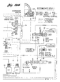
- FIGs 19a through 26a and in Figures 19b through 26b Two different versions of the shift valve configuration for 3-4, 4-3 and 5-3 shifts are shown respectively in Figures 19a through 26a and in Figures 19b through 26b.
- the first and second versions for third gear are shown in Figures 19a and 19b and in Figures 23a and 23b, respectively.
- the valve positions for intermediate step 1, first version is shown in Figures 20a and 20b.
- Figures 24a and 24b show the second version for the intermediate step 1.
- Figures 21a and 21b show the valve positions for intermediate step 2, first version, and Figures 25a and 25b show the valve positions for intermediate step 2, second version.
- Figures 22a and 22b show the fourth gear valve positions, first version, and Figures 26a and 26b show the fourth gear valve positions, second version.
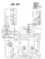
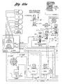
- Figure 19b shows two ON/OFF solenoids for shift control at 62 and 64, respectively.
- the corresponding ON/OFF solenoids for the second version use the same numerals although prime notations are added. These solenoids also carry the notations SS1 and SS2, respectively.
- the system includes also one main regulator valve including a booster valve, as shown at 66 for the first version and at 66' for the second version. It also includes two modulator valves VFS1/MOD and VFS3/MOD. VFS1 is shown at 82 for the first version and at 82' for the second version.
- VFS3/MOD valve Variable force solenoid modulator
- VFS3/MOD valve Variable force solenoid modulator
- the system also has one solenoid pressure regulator valve shown at 70 and 70' for the first and second versions, respectively. It also has three shift valves as shown at 72, 74 and 76 in the case of the first version and at 72', 74' and 76' in the case of the second version.
- the two variable force solenoid valves VFS1 and VFS3 previously discussed, actuate the two modulator valves.
- the differences in the two versions reside in the intermediate servo control valve at 74 and 74' and the high clutch shift control valve 76 and 76', as well as the additional VFS/MOD valve 68" f)r the second version.
- the second version has separate exhaust ports for the intermediate servo release side which is identified as ISR/EX in Figure 24b next to valve 76'.
- the exhaust port for tie intermediate servo and the high clutch is common and is located at the shift valve 76.
- the high clutch exhaust port is shown in Figure 19b, but a corresponding port does not appear in Figure 24b for the second version.
- the first version has a differential area 78 on shift valve 74 in Figure 19a where an electronically controlled pressure EPC1 is applied. This pressure EPC1 interlocks the shift valve 74 when a 3-4 upshift is complete.
- Figure 24a for the second version has an additional valve VFS3/MOD valve in front of the variable force solenoid VFS3. Either VFS3 or VFS3/MOD pressure can be connected to the high clutch C2 and the intermediate servo release by the orifices 1 and 2 shown in Figures 23a and 23b, respectively, and identified by reference numerals 40 and 38, respectively, as previously indicated in Figure 13.
- VFS3/MOD valve One version of the VFS3/MOD valve is shown in Figures 23a through 26a at 68" for the second control version.
- This modulator valve version has a differential area that multiplies VFSS/MOD pressure relative to EPC3 pressure. This feature adjusts the clutch capacity in order to meet the requirements of different engine sizes.
- the VFS3/MOD valve X, 80' X has one diameter. EPC3 pressure is applied to the top and VFS3/MOD pressure is applied to the back.
- the pressure build-up system includes two variable force solenoids, shown at 82 and 84 in Figure 19a. It includes also two clutch pressure modulator valves previously described with reference to Figure 23a to enhance the independent capacity control of intermediate servo B2 and high clutch C2.
- the electronic pressure control system also includes two variable force solenoids 82 and 84 for controlling B2 and C2, respectively.
- the hydraulic control system elements that control the 3-4 upshift are shown in Figures 19a and 19b, 23a and 23b, Figure 20a and 20b, Figure 24a and 24b, Figure 22a and 22b, and Figure 26a and 26b.
- the solenoid stages that are needed to execute a 3-4 upshift are shown in the following table along with the pressures applied on each affected element during the transition from third gear to fourth gear.
- Intermediate step 1 is introduced, which initiates the upshifting event of the Simpson planetary gear set.
- the 3-4 upshift is a synchronous upshift where the high clutch C2 is engaged and the intermediate brake band B2 is released. Synchronization takes place between the ring gear and the stationary sun gear of the first planetary gear unit for the Simpson gear set. The stationary sun gear is released by brake B2 at the same time clutch CL2 is engaging and accelerating the sun gear up to the input shaft speed. The sun gear, the ring gear, and the carrier rotate with input shaft speed. If this synchronization is not accomplished, capacity loss and engine speed flare-up may occur.
- the capacity of the high c.utch is designed for holding the maximum capacity in reverse.
- the high clutch carries 1*input shaft torque.
- the high clutch In fourth gear or during a 3-4 upshift, the high clutch carries only a fraction of the input shaft torque depending on the gear ratio.
- the intermediate servo stroke volume is used to accumulate the high clutch capacity.
- solenoid 62 (SS1) and solenoid 64 (SS2) are turned on.
- This solenoid s:age is shown in Figure 19b and in Figure 23b.
- shift solenoid 62 is turned on, the high clutch control valve 76 and the intermediate servo control valve 74 are in the upshift position.
- the intermediate servo release pressure chamber is exhausted over the ISR/EX port in the shift valve 76'.
- the high clutch is exhausted separately into the CR/R/EX circuit shown at 76' in Figure 23b.
- the intermediate servo release pressure chamber and the high clutch are commonly exhausted into the HC/EX port over the high clutch control valve 76 seen in Figure 19b.
- the shift valve 72 is in the downshift position. It then connects the VFS1/MOD valve 68 to the intermediate servo apply side, thus building up the intermediate band capacity for third gear operation.
- the VFS1/MOD valve 68 communicates with line pressure (D/3/2/1). That pressure is the same as the line pressure distributed by the manual valve 88 to the VFS1 modulator valve 68.
- the VFS1/MOD pressure applied to the intermediate servo apply side is a modulated clutch pressure characteristic of the line pressure (D/3/2/1) and the VFS1/MOD pressure, as shown in Figure 15 where these pressures are plotted against various values for line pressure.
- the major advantage of using the VFS1 modulator valve is that the intermediate brake band capacity as well as the high clutch capacity, during a 3-4 upshift can be varied from zero pressure to a pressure that satisfies the maximum capacity requirements.
- Both circuits first are filled. After filling, the high clutch is stroked up to the high clutch engagement point by compressing the high clutch disks. The high clutch pressure and the capacity thus increase. The same pressure is applied on the intermediate servo release side. The torque phase of the 3-4 upshift then is initiated. Line pressure is distributed to the variable force solenoid 84 and to the VFS3/MOD valve of Figure 24a, which enables the variable force solenoid or the VFS3/MOD valve to produce variable flow rates by adjusting variable differential pressures D? across the VFS3 84 or 84' or the VFS3/MOD valve 68''. Variable flow rates can now be used to produce various capacity slopes for the high clutch, thereby influencing the shift quality accordingly.
- the torque phase characteristic can be adjusted to various shifts during various operating modes.
- the intermediate servo starts to stroke. This is the point where the high clutch trarsmits full torque and the reaction torque on intermediate servo B2 is zero.
- the inertia phase is initiated.
- the variable flow rate for the variable force solenoid 3, shown at 84, or the flow rate from the VFS3/MOD valve 68" of Figure 24a is now used to control the stroke time of the intermediate servo.
- the accumulation time can be increased or decreased for a given operating mode for the transmission.
- EPC3 pressure or VFS3/MOD pressure
- VFS3/MOD pressure can then be used to control the high clutch pressure.
- EPC1 pressure from variable force solenoid 82 is lowered and EPC3 pressure or VFS3/MOD pressure is adjusted to the required high clutch capacity to complete the 3-4 upshift.
- the transmission then is in fourth gear. This makes it possible to control the inertia phase of the 3-4 upshift independently of the intermediate servo stroke distance. This increases the robustness of the 3-4 shift quality. Degrading of the 3-4 upshift quality by a grounded intermediate servo prior to completion of the shift is prevented in this way.
- the solenoid states are as shown in Figures 22b or 26b. In this case, both shift solenoids are turned off.
- the 3-4 upshift is complete in the intermediate step 1.
- the intermediate servo control valve 74 is downshifted. This connects line pressure to the intermediate servo release side This is required in order to prevent the intermediate servo from stroking when high VFS1/MOD pressure on the intermediate servo apply side and low EPC3 pressure or VFS3/MOD pressure are commanded. In this way, simultaneous engagement of the intermediate brake band and the high clutch is prevented. Tie-up of the Simpson gear set thus is avoided.
- Figure 16 is a timing chart for a 3-4 upshift event.
- the symbols that appear in Figure 16 are identified in the following table:
- the driver indicates that he desires a 3-4 upshift, which is triggered by functions of throttle position versus vehicle speed.
- the GR_DS register is changed from 4 and the shift verification timer TM_VER_SFT is loaded.
- the EPC1 pressure is set to satisfy static intermediate band capacity and the capacity for a dynamic 3-4 upshift.
- the EPC3 pressure value or the VFS3/MOD pressure value is set to fill the intermediate servo release and high clutch chambers and to control the high clutch stroke times.
- the VFS1/MOD pressure rises due to the desired EPC1 pressure value.
- the EPC3 pressure value increases as discussed previously.
- the shift solenoid 1 is deenergized and the high clutch control valve in bore 212 moves into downshift position. This connects EPC3 or VFS3/MOD pressure to the high clutch and the intermediate servo release side. The filling process starts.
- the EPC3 values are set to control the flow rates entering the high clutch and intermediate servo release side in an open loop controlled manner.
- the high clutch and the intermediate servo release pressure increase.
- the high clutch starts to transmit torque.
- the intermediate brake torque is reduced by the increased intermediate servo release pressure.
- the slope of the high clutch pressure characteristic is controlled by the EPC3 pressure settings or by the VFS3/MOD pressure settings.
- the B2 reaction torque is zero.
- the torque phase of the shift is complete.
- the output shaft torque signature is now proportional to the high clutch capacity slope.
- the inertia phase is initiated.
- the EPC3 pressure level is set to control the strcke time of the intermediate servo.
- the high clutch pressure is now in equilibrium with the intermediate servo apply pressure and the intermediate servo starts to stroke.
- the EPC3 or VFS3/MOD flow rates control the stroke time of the intermediate servo. In the time range from t4 through t6, EPC3 flow control or VFS3/MCD flow control determines the torque phase characteristic and the change over characteristic from the torque phase to the inertia phase.
- the EPC3 pressure level is set to satisfy high clutch capacity since the intermediate servo stroke phase is ending. This control action is only necessary when the servo stroke is too short to cover the inertia phase of the shift. EPC1 pressure is lowered to prevent a restroking of the intermediate servo.
- the EPC3 pressure settings are set to effect high clutch capacity.
- the accumulation phase generated by the intermediate servo stroke volume is complete since the intermediate servo is grounded. From t6 through t7, the accumulation time is controlled by EPC3 flow control or by VFS3/MOD flow control.
- the EPC3 pressure level is set to a safe value since the 3-4 upshift is now complete.
- the shift solenoid 2 is deenergized by setting FLG_SS_2 to zero.
- control system of the invention uses an additional solenoid VFS3 in front of the flow control orifice instead of applying line pressure directly to the clutch and the brake. This allows a control of flow rates entering the intermediate servo release chamber and the high clutch pressure chamber by adjusting independently controlled delta pressures.
- the accumulation time can be influenced during the stroke phase and the high clutch capacity can be directly controlled by the additional variable force solenoid valve when the servo is grounded.
- the transmission has two solenoid stages that are arranged to function as intermediate steps between third gear and fourth gear.
- the two intermediate steps IS1 and IS2 are achieved with shift solenoids SS1, SS2 and EPC3 control.
- the solenoid stages that accomplish these intermediate steps are indicated in the following table.
- the intermediate servo apply pressure is controlled, as previously explained, by the VFS1/MOD pressure system.
- EPC3 pressure generated by the variable force solenoid 84 is dedicated to the high clutch for independent capacity and deceleration profile control of the sun gear for the Simpson gear set.
- a first option on a 4-3 downshift provides fourth gear, intermediate step 1, and third gear in that order. This option allows high clutch capacity control, as well as prestroke control of the intermediate servo, to match the zero speed synchronization point. This option can be used for high torque and low speed downshifts.
- a second option uses the sequence: fourth gear, intermediate step 2 and third gear. This option allows high clutch capacity control and prevents the intermediate servo from stroking. Here, no prestroke of the intermediate servo is required. Therefore, this option can be used for low torque and high speed downshifts.
- the sequence On a 5-3 downshift, the sequence is the same as the 4-3 downshift sequence (i.e. 5-IS1-3 or 5-IS2-3).
- the overdrive band is applied and has to be released instantly when a 5-3 downshift is in progress.
- Intermediate step 2 (IS2) during a 4-3 downshift is the same as in fourth gear. This means that all the shift valves remain in the downshift position.
- the intermediate servo release side is applied with line pressure and the high clutch is controlled with EPC3 pressure or VFS3/MOD pressure. This is shown in Figures 21a and 21b and in Figures 25a and 25b.
- EPC3 pressure or VFS3/MOD pressure This initiates a 4-3 downshift by reducing EPC3 pressure or the VFS3/MOD pressure that is applied to the high clutch.
- the reduction of EPC3 pressure or VFS3/MOD pressure allows the deceleration of the high clutch drum, which is connected to the sun gear of the Simpson gear set.
- Open loop control or closed loop control can now be applied to control deceleration or deceleration rate of the high clutch drum speed. Closed loop is carried out by using the high clutch drum speed as a feedback signal. In order to apply a closed loop control to the high clutch, very accurate and small delta pressures are necessary. Therefore, the output pressure of VFS3 is either directly connected to the high clutch without amplification or a VFS3/MOD valve is used with a small pressure amplification.
- the intermediate step 1 of the 4-3 downshift control is the same solenoid stage previously described and is shown in Figures 20a and 20b and in Figures 24a and 24b.
- the shift solenoid 2 is energized. This connects the intermediate servo release side with EPC3 pressure or VFS3/MOD pressure which is distributed also to the high clutch.
- the intermediate servo apply side that is subjected to VFS1/MOD pressure can now be used to prestroke the servo during high clutch drum speed profile control.
- EPC3 pressure is set to pressure levels to control with either open loop or closed loop the deceleration of the high clutch drum, as explained above.
- the intermediate step now allows simultaneous control of the high clutch capacity and the servo stroke phase. Independent control of intermediate brake band capacity, executed by VFS1 and zero high clutch drum speed provided by VFS3, now is possible. This enables accurate synchronization betweer the engagement of 82 and the zero speed crossing for C2.
- the engagement of the intermediate brake band B2 is also triggered by a high clutch drum speed threshold that is lower than a calibratable value.
- Option 1 as shown in Figure 18 of the simplified strategy, would use intermediate step 1.
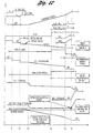
- option 2 as shown in Figure 17, intermediate step 2 would be used.
- the driver desires a 4-3 downshift, which is triggered by functions of throttle position versus vehicle speed.
- the GR_DS register is changed to 3 and the shift verification timer TM_VER_SFT is loaded.
- the EPC3 pressure value is set to an initial value to get prepared for closed loop control.
- the EPC3 pressure or VFS3/MOD pressure is set to an initial value, which still holds high clutch capacity.
- EPC3 HOLD TQ SIMP * RATIO c 2 GAIN c 2
- the shift solenoid flag 1 FLG_SS_1 is set to 1.
- the EPC3 pressure or VFS3/MOD pressure is decreased on the high clutch since EPC3 pressure has been decreased to a "HOLD" level which marginally holds CL2 capacity.
- the high clutch capacity can be manipulated by the EPC3 settings or by the VFS3/MOD settings and high clutch drum slip can be introduced prior to closed loop control clutch capacity.
- the shift solenoid 1 is deenergized and the high clutch control valve 76 moves into downshift position. This connects EPC3 pressure or VFS3/MOD pressure to the high clutch and the intermediate servo release side and allows the intermediate servo to be prestroked.
- a PID controller is used to control with capacity manipulation the derivative of the high clutch drum speed (dHCDS/dt).
- the control block diagram is shown in Figure 9.
- the target derivative high clutch drum speed is calculated from tables of throttle position versus vehicle speed. This is required in order to have dedicated target values for dedicated shifts at cedicated vehicle speeds and throttle positions. The individual target value will be adjusted for a dedicated downshift by a multiplier which is a function of gear ratio. This multiplier provides an opportunity to design a derivative of second order.
- DHCDS_TRG DHCDS_TRG*FN(RATIO)
- e_DHCDS DHCDS_ACT- DHCDS_TRG
- DP_PID Kc*(Kp*(e_HCDS_T0-e_HCDS_T1)+Ki*e_HCDS_T0 +Kd*(e_HCDS_T0-2*e_HCDS_T1+e_HCDS_T2)).
- the controller gains should be selectable from a table of throttle position (TP) versus vehicle speed (VS). This is required since the 4-3 downshifts occur at different throttle positions and vehicle speeds.
- EPC3 is the control pressure to manipulate the high clutch capacity (C2).
- C2 high clutch capacity
- the EPC3 calculation takes the error between the actual derivative high clutch drum speed DHCDS and the target derivative high clutch drum speed into account and converts the calculated error in an EPC3 value. This adjusts the deceleration characteristic of the high clutch drum.
- the high clutch pressure is decreased or increased depending on the control pressure applied on the clutch to follow the target high clutch drum speed profile.
- the high clutch drum speed is less than a calibratable value 1.
- the high clutch drum speed threshold value (which is referred to as "calibratable value 1" in Figure 18) when the intermediate servo starts to stroke can be calculated. This leads then to an accurate synchronization cf the zero speed crossing of the high clutch drum speed and the engagement of the intermediate band.
- the EPC1 pressure is raised to accelerate the intermediate servo stroke phase, which is initiated at point t5.
- option 1 the VFS1/MOD pressure is raised and the intermediate servo starts to stroke to meet the synchronization point at t6.
- VFS1/MOD pressure is raised to a level, which causes a fast intermediate servo stroke phase initiated at point t5.
- the high clutch drum speed is smaller than a calibratable value 2, which triggers the reset of shift solenoid flags FLG_SS_1 and FLG_SS_2. This initiates the intermediate servo stroke phase.
- the shift solenoids 62 and 64 are energized.
- the high clutch control valve in bore 76 and the intermediate servo control valve 74 are downshifted.
- the high clutch and the intermediate servo release pressures are exhausted as previously explained.
- the high clutch drum speed will now be decelerated by the engine torque without EPC3 pressure control.
- a second shift slope is initiated, which leads to the zero speed crossing point.
- the intermediate servo starts to stroke in order to meet the synchronization point at t6.
- the shift solenoid flag 1 FLG_SS_1 is set to 1.
- the high clutch drum speed is at or near zero.
- the intermediate servo engages and transmits torque.
- the B2 reaction torque increases.
- the B2 sun gear torque of the Simpson planetary gear set is grounded against the transmission case by the intermediate brake band.
- the transmission is in third gear.
- the shift solenoid 1 is energized. This moves the high clutch control valve into downshift position.
- the high clutch and the intermediate servo release pressure are exhausted through the shift valve 74 into the ISR/EX and CR/R/EX ports (see Figures 20a, 20b, 24a and 24b).
- both pressures were controlled and exhausted over the VFS3-EX port at the variable force solenoid 84 (VFS3).
- the shift sequence for open loop controlled 4-3/5-3 downshifts are the same as the closed loop controlled shifts described above.
- the open loop control method would use EPC3 pressure ramps to trigger the deceleration of the high clutch drum speed.
- the high clutch drum speed would then be monitored and the servo stroke phase then would be initiated (t4).
- an open loop control timer could be used. It would start expiring from t2 and would expire at t4, for example, to trigger the intermediate servo stroke phase.
Landscapes
- Engineering & Computer Science (AREA)
- General Engineering & Computer Science (AREA)
- Physics & Mathematics (AREA)
- Fluid Mechanics (AREA)
- Mechanical Engineering (AREA)
- Control Of Transmission Device (AREA)
Claims (6)
- Ein Mehrgang-Automatikgetriebe, das von einem Motor zu einer Drehmoment-Abgabewelle eine Mehrzahl von Drehmoment-Durchflußwegen schafft; und das umfaßt:gekennzeichnet durchPlanetengetriebe-Elemente (10) einschließlich eines Aufbaus aus einem zentrale Ritzel (18), einem Hohlrad (14) und einem Planetenträger (16), der diese Drehmoment-Durchflußwege definiert;eine Kupplungsvorrichtung für hohes Übersetzungsverhältnis (C2), um zwei dieser Planetengetriebe-Elemente (14, 18) zur Drehung im Einklang miteinander zu verbinden, um dadurch ein hohes Übersetzungsverhältnis zu schaffen; wobei die Kupplungsvorrichtung (C2) einen Kupplungsservo für hohes Übersetzungsverhältnis einschließt, der eine Kupplungs-Arbeitsdruckkammer (C2-APPLY) besitzt;eine Untersetzungs-Bremsvorrichtung (B2), um eines dieser Getriebeelemente (18) zu verankern, um dadurch ein Untersetzungsverhältnis zu schaffen, wobei die Untersetzungs-Bremsvorrichtung (B2) einen Untersetzungs-Bremsenservo einschließt, der eine Bremsen-Arbeitsdruckkammer (B2-APPLY) und eine Bremsen-Freigabedruckkammer (B2-RELEASE) besitzt, die durch ein bewegliches Bremsen-Stellglied voneinander getrennt sind; undein Regelventil-System, das eine motorbetriebene Regeldruckpumpe aufweist; eine erste mittels Elektromagnet betätigte Ventilvorrichtung (VFS1), um den Druck in dieser Bremsen-Arbeitsdruckkammer (B2-APPLY) zu regeln; und eine zweite mittels Elektromagnet betätigte Ventilvorrichtung (VFS3), um den Druck in dieser Bremsen-Freigabedruckkammer (B2-RELEASE) und in dieser Kupplungs-Arbeitsdruckkammer (C2-APPLY) zu regeln; wobei diese erste mittels Elektromagnet betätigte Ventilvorrichtung (VFS1) eine variable Zwischenbremsenservo-Arbeitskraft auf dieses Bremsenstellglied bewirkt, und diese zweite mittels Elektromagnet betätigte Ventilvorrichtung (VFS3) eine variable Zwischenbremsenservo-Freigabekraft auf dieses Bremsenstellglied bewirkt;eine erste Modulatorventilvorrichtung (VFS1/MOD), die zum Teil eine Fluidverbindung zwischen dieser ersten mittels Elektromagnet betätigten Ventilvorrichtung (VFS1) und dieser Bremsen-Arbeitsdruckkammer (B2-APPLY) definiert, um die Rate des Druckaufbaus in dieser Zwischenservo-Arbeitsdruckkammer zu modifizieren; und eine zweite Modulatorventilvorrichtung (VFS3/MOD), die zum Teil eine Fluidverbindung zwischen dieser zweiten mittels Elektromagnet betätigten Ventilvorrichtung (VFS3) und sowohl dieser Kupplungs-Arbeitsdruckkammer für hohes Übersetzungsverhältnis (C2-APPLY) wie auch dieser Untersetzungsbremsen-Freigabedruckkammer (B2-RELEASE) definiert, um die Rate des Druckanstiegs in dieser Kupplungs-Arbeitsdruckkammer für hohes Übersetzungsverhältnis und dieser Untersetzungsbremsen-Freigabedruckkammer zu modifizieren; um dadurch für die Trägheitsphase des Hochschaltens eine Variation in der Dauer und in der Drehmomentcharakteristik zu ermöglichen.
- Ein Mehrgang-Automatikgetriebe gemäß Anspruch 1, das weiterhin einen elektronischen Regler (50) umfaßt, der Speicherabschnitte, einen Prozessorabschnitt, Signaleingabe-Abschnitte und Ausgabetreiber-Abschnitte aufweist; wobei letztere elektronisch an diese Schaltregelventil-Vorrichtung und an diese ersten und zweiten mittels Elektromagnet betätigten Ventilvorrichtungen und Vorrichtungen angeschlossen sind, um vom Fahrer ausgewählte Eingabe-Regelsignale, Motordrehzahl- und Drehmoment-Eingabesignale und Getriebebetriebs-Eingabesignale zu entwickeln; wobei diese Signalentwicklungs-Vorrichtung an diese Signaleingabe-Abschnitte angeschlossen ist, und worin diese Kupplung für hohes Übersetzungsverhältnis eine Kupplungstrommel einschließt, die an Reaktionselemente dieser Planetengetriebe-Elemente angeschlossen sind; und diese Getriebebetriebs-Signale ein Direktkupplungstrommel-Drehzahlsignal (HDCSS) einschließt.
- Ein Mehrgang-Automatikgetriebe gemäß Anspruch 2, einschließlich Vorrichtungen zur elektronischen Regelung der Sysnchronisierung des Anlegens von Bremsmoment dieses Zwischenbremsenservos bei Nulldrehzahl dieser Kupplungstrommel, um dadurch die Qualität von Rückschaltvorgängen bei niedriger Drehzahl und hohem Drehmoment und von Rückschaltvorgängen bei hoher Drehzahl und niedrigem Drehmoment zu verbessern.
- Ein Mehrgang-Automatikgetriebe gemäß Anspruch 3, im dem diese Vorrichtungen zur elektronischen Regelung der Synchronisierung einen Trommeldrehzahl-Sensor zur Überwachung der Drehzahl dieser Kupplungstrommel einschließen, und Vorrichtungen zur Überwachung der Verzögerung dieser Kupplungstrommel-Drehzahl während eines Schaltintervalls mittels einer Regelschleifen-Rückführung, um dadurch eine Synchronisierung der Bremsenservo-Anwendung bei einer Drehzahl dieser Kupplungstrommel für hohes Übersetzungsverhältnis zu erhalten, die nahe Null liegt; indem man die Kapazität der Kupplung für hohes Übersetzungsverhältnis regelt.
- Ein Mehrgang-Automatikgetriebe gemäß einem der vorstehenden Ansprüche, einschließlich eines mit dieser zweiten mittels Elektromagnet betätigten Ventilvorrichtung kommunizierenden Systemdruck-Regulators, um ein elektronisches Druck-Regelsignal auf dieses Systemdruck-Regulierventile anzuwenden, um die Drehmomentkapazität dieses Direktkupplungsservos und dieser Untersetzungsbremsenservo-Freigabedruckkammer zu ändern.
- ein Schaltregelventil-System gemäß einem der vorstehenden Ansprüche, in dem diese mittels Elektromagnet betätigten Ventilvorrichtungen (VFS1 und VFS3) Elektromagneten mit variabler Kraft umfassen.
Applications Claiming Priority (2)
| Application Number | Priority Date | Filing Date | Title |
|---|---|---|---|
| US996489 | 1997-12-23 | ||
| US08/996,489 US6122583A (en) | 1997-12-23 | 1997-12-23 | Upshift and downshift control valve system for multiple ratio automatic transmission |
Publications (3)
| Publication Number | Publication Date |
|---|---|
| EP0926404A2 EP0926404A2 (de) | 1999-06-30 |
| EP0926404A3 EP0926404A3 (de) | 1999-11-24 |
| EP0926404B1 true EP0926404B1 (de) | 2004-02-25 |
Family
ID=25542983
Family Applications (1)
| Application Number | Title | Priority Date | Filing Date |
|---|---|---|---|
| EP98310408A Expired - Lifetime EP0926404B1 (de) | 1997-12-23 | 1998-12-18 | Steuerventilsystem für ein mehrgängiges Automatikgetriebe |
Country Status (3)
| Country | Link |
|---|---|
| US (1) | US6122583A (de) |
| EP (1) | EP0926404B1 (de) |
| DE (1) | DE69821892T2 (de) |
Families Citing this family (19)
| Publication number | Priority date | Publication date | Assignee | Title |
|---|---|---|---|---|
| US6301538B1 (en) * | 2000-06-07 | 2001-10-09 | Ford Global Technologies, Inc. | Swap shift multiple-ratio automatic transmission |
| US6385520B1 (en) | 2000-08-10 | 2002-05-07 | Ford Global Technologies, Inc. | Control strategy and method for independently controlling friction element actuators for an automatic transmission |
| US6549838B2 (en) | 2001-05-21 | 2003-04-15 | Ford Global Technologies, Inc. | High energy engagement strategy for automatic transmission clutches and brakes |
| US6393350B1 (en) | 2001-08-10 | 2002-05-21 | Ford Global Technologies, Inc. | Powertrain controller using a feed-forward torque calculation |
| EP1353095A1 (de) * | 2002-04-10 | 2003-10-15 | Van Doorne's Transmissie B.V. | Steuerungsverfahren für ein automatisches Getriebe |
| US6577939B1 (en) | 2002-05-20 | 2003-06-10 | Ford Global Technologies, Llc | Pressure control system and control method for a multiple-ratio transmission with pre-staged ratio shifts |
| US7356398B2 (en) * | 2003-10-14 | 2008-04-08 | General Motors Corporation | Synchronous shift control in an electrically variable transmission |
| US7107135B2 (en) * | 2003-10-31 | 2006-09-12 | Ford Global Technologies, Llc | Auxiliary gearset shift progression command generator for a swap-shift automatic transmission |
| US6961646B2 (en) * | 2003-10-31 | 2005-11-01 | Ford Global Technologies, Llc | Automatic transmission control system with direct electronic swap-shift control |
| US7324885B2 (en) * | 2004-02-14 | 2008-01-29 | General Motors Corporation | Shift through neutral control in an electrically variable transmission |
| WO2005119096A2 (en) * | 2004-06-01 | 2005-12-15 | Carne Gary S | Transmission pressure modulation by orificed check valve |
| US9404575B2 (en) * | 2007-06-29 | 2016-08-02 | GM Global Technology Operations LLC | Transmission upshift flare detection and mitigation |
| US9056610B2 (en) * | 2008-03-13 | 2015-06-16 | Ford Global Technologies, Llc | Transmission downshift input torque modulation for a hybrid electric vehicle |
| WO2010105671A1 (en) * | 2009-03-17 | 2010-09-23 | Flanders' Mechatronics Technology Centre Vzw | Method for controlling a torque transmitting device with learning function |
| US8255130B2 (en) * | 2009-04-09 | 2012-08-28 | Ford Global Technologies, Llc | Closed-loop torque phase control for shifting automatic transmission gear ratios based on friction element load sensing |
| US8342998B2 (en) * | 2009-04-09 | 2013-01-01 | Ford Global Technologies, Llc | Friction element load sensing in an automatic transmission |
| CA2754137C (en) * | 2011-09-30 | 2012-11-20 | Westport Power Inc. | Apparatus and method for in situ fuel injector calibration in an internal combustion engine |
| CN104040189B (zh) | 2012-01-11 | 2016-12-07 | 伊顿公司 | 控制流体压力致动的切换构件的方法和用于该切换构件的控制系统 |
| DE102016217096A1 (de) * | 2016-09-08 | 2018-03-08 | Audi Ag | Verfahren zum Synchronisieren zweier Antriebselemente eines Antriebsstrangs eines Kraftfahrzeugs, sowie Antriebsstrang für ein Kraftfahrzeug |
Family Cites Families (11)
| Publication number | Priority date | Publication date | Assignee | Title |
|---|---|---|---|---|
| US3956947A (en) * | 1974-06-14 | 1976-05-18 | Chrysler Corporation | Adaptive control system for automatic transmission |
| US4838126A (en) * | 1987-11-25 | 1989-06-13 | Btr Engineering (Australia) Limited | Electro/hydraulic control system for an automatic transmission |
| JPH0565957A (ja) * | 1991-09-04 | 1993-03-19 | Nissan Motor Co Ltd | 自動変速機の変速制御装置 |
| JPH07280064A (ja) * | 1994-03-31 | 1995-10-27 | Komatsu Ltd | 油圧機械式動力伝達装置の動力伝達方法 |
| US5612874A (en) * | 1994-10-14 | 1997-03-18 | Ford Motor Company | Multiple ratio automatic transmission with solenoid operated valves for effecting pressure buildup |
| US5586029A (en) * | 1994-10-14 | 1996-12-17 | Ford Motor Company | Shift control system for a multiple ratio automatic transmission with manual ratio ranges |
| US5553694A (en) * | 1994-10-14 | 1996-09-10 | Ford Motor Company | Multiple ratio automatic transmission and torque converter |
| US5646842A (en) * | 1994-10-14 | 1997-07-08 | Ford Motor Company | Shift control system for a multiple ratio automatic transmission |
| US5835875A (en) * | 1995-10-27 | 1998-11-10 | Ford Global Technologies, Inc. | Swap-shift control system for a multiple ratio transmission |
| US5642283A (en) * | 1995-10-27 | 1997-06-24 | Ford Motor Company | Multiple ratio transmission with swap-shift controls |
| JP3687183B2 (ja) * | 1996-03-31 | 2005-08-24 | マツダ株式会社 | 自動変速機の制御装置 |
-
1997
- 1997-12-23 US US08/996,489 patent/US6122583A/en not_active Expired - Lifetime
-
1998
- 1998-12-18 DE DE69821892T patent/DE69821892T2/de not_active Expired - Lifetime
- 1998-12-18 EP EP98310408A patent/EP0926404B1/de not_active Expired - Lifetime
Also Published As
| Publication number | Publication date |
|---|---|
| DE69821892T2 (de) | 2005-01-05 |
| US6122583A (en) | 2000-09-19 |
| EP0926404A3 (de) | 1999-11-24 |
| DE69821892D1 (de) | 2004-04-01 |
| EP0926404A2 (de) | 1999-06-30 |
Similar Documents
| Publication | Publication Date | Title |
|---|---|---|
| EP0926404B1 (de) | Steuerventilsystem für ein mehrgängiges Automatikgetriebe | |
| EP0770800B1 (de) | Ein automatisches Getriebe | |
| EP0825366B1 (de) | Schaltsteuerung bei Gruppenwechsel eines mehrstufigen Getriebes | |
| EP0707164B1 (de) | Schaltsteuerung für ein automatisches Mehrganggetriebe | |
| EP0821189B1 (de) | Mehrgängiges Getriebe mit Einrichtung zur gleichzeitigen Steuerung mehrerer Getriebestufen | |
| EP0322111B1 (de) | Ereignisfolgenbedingtes Kupplung-zu-Kupplung-Herunterschalten für ein elektronisch gesteuertes automatisches Getriebe | |
| US4131036A (en) | Method and apparatus for transmission control system | |
| US6385520B1 (en) | Control strategy and method for independently controlling friction element actuators for an automatic transmission | |
| US6626786B2 (en) | Speed shift control apparatus of automatic transmission | |
| EP0707165B1 (de) | Automatisches Mehrganggetriebe mit Drehmomentwandler | |
| JP3540529B2 (ja) | 自動変速機の油圧制御装置 | |
| EP0814285B1 (de) | Automatisches Mehrganggetriebe und Drehmomentwandler mit Überbrückungskupplung | |
| JP3467934B2 (ja) | 自動変速機のダウンシフト制御装置 | |
| US8267836B2 (en) | Control system for automatic transmission | |
| US6370463B1 (en) | Strategy for controlling ratio changes in a swap-shift automatic transmission | |
| US5586029A (en) | Shift control system for a multiple ratio automatic transmission with manual ratio ranges | |
| KR101380819B1 (ko) | 차량용 자동변속기 및 차량용 자동변속기의 작동 제어방법 | |
| US6464609B1 (en) | Hydraulic control for a six-speed automatic transmission | |
| US20040192500A1 (en) | Control apparatus and control method for automatic transmission | |
| US6123645A (en) | Neutral idle control mechanism for a torque-transmitting clutch in a power transmission | |
| EP0933562B1 (de) | System zur Eingriffssteuerung, vorwärts und rückwärts, eines automatischen Mehrganggetriebes | |
| US5596495A (en) | Gearshift controller for automatic transmission | |
| US6258010B1 (en) | Transmission shifting hydraulic control system | |
| JP3937122B2 (ja) | 自動変速機の目標油圧判断装置 | |
| US6074319A (en) | Ratio change control system for multiple ratio transmission |
Legal Events
| Date | Code | Title | Description |
|---|---|---|---|
| PUAI | Public reference made under article 153(3) epc to a published international application that has entered the european phase |
Free format text: ORIGINAL CODE: 0009012 |
|
| AK | Designated contracting states |
Kind code of ref document: A2 Designated state(s): DE FR GB |
|
| AX | Request for extension of the european patent |
Free format text: AL;LT;LV;MK;RO;SI |
|
| PUAL | Search report despatched |
Free format text: ORIGINAL CODE: 0009013 |
|
| AK | Designated contracting states |
Kind code of ref document: A3 Designated state(s): AT BE CH CY DE DK ES FI FR GB GR IE IT LI LU MC NL PT SE |
|
| AX | Request for extension of the european patent |
Free format text: AL;LT;LV;MK;RO;SI |
|
| RIC1 | Information provided on ipc code assigned before grant |
Free format text: 6F 16H 61/06 A, 6F 16H 59/38 B |
|
| 17P | Request for examination filed |
Effective date: 20000323 |
|
| AKX | Designation fees paid |
Free format text: DE FR GB |
|
| 17Q | First examination report despatched |
Effective date: 20020903 |
|
| GRAH | Despatch of communication of intention to grant a patent |
Free format text: ORIGINAL CODE: EPIDOS IGRA |
|
| GRAS | Grant fee paid |
Free format text: ORIGINAL CODE: EPIDOSNIGR3 |
|
| RAP1 | Party data changed (applicant data changed or rights of an application transferred) |
Owner name: FORD GLOBAL TECHNOLOGIES, LLC |
|
| GRAA | (expected) grant |
Free format text: ORIGINAL CODE: 0009210 |
|
| AK | Designated contracting states |
Kind code of ref document: B1 Designated state(s): DE FR GB |
|
| REG | Reference to a national code |
Ref country code: GB Ref legal event code: FG4D |
|
| REF | Corresponds to: |
Ref document number: 69821892 Country of ref document: DE Date of ref document: 20040401 Kind code of ref document: P |
|
| ET | Fr: translation filed | ||
| PLBE | No opposition filed within time limit |
Free format text: ORIGINAL CODE: 0009261 |
|
| STAA | Information on the status of an ep patent application or granted ep patent |
Free format text: STATUS: NO OPPOSITION FILED WITHIN TIME LIMIT |
|
| 26N | No opposition filed |
Effective date: 20041126 |
|
| PGFP | Annual fee paid to national office [announced via postgrant information from national office to epo] |
Ref country code: GB Payment date: 20131126 Year of fee payment: 16 |
|
| PGFP | Annual fee paid to national office [announced via postgrant information from national office to epo] |
Ref country code: FR Payment date: 20131126 Year of fee payment: 16 |
|
| PGFP | Annual fee paid to national office [announced via postgrant information from national office to epo] |
Ref country code: DE Payment date: 20131230 Year of fee payment: 16 |
|
| REG | Reference to a national code |
Ref country code: DE Ref legal event code: R119 Ref document number: 69821892 Country of ref document: DE |
|
| GBPC | Gb: european patent ceased through non-payment of renewal fee |
Effective date: 20141218 |
|
| REG | Reference to a national code |
Ref country code: FR Ref legal event code: ST Effective date: 20150831 |
|
| PG25 | Lapsed in a contracting state [announced via postgrant information from national office to epo] |
Ref country code: DE Free format text: LAPSE BECAUSE OF NON-PAYMENT OF DUE FEES Effective date: 20150701 Ref country code: GB Free format text: LAPSE BECAUSE OF NON-PAYMENT OF DUE FEES Effective date: 20141218 |
|
| PG25 | Lapsed in a contracting state [announced via postgrant information from national office to epo] |
Ref country code: FR Free format text: LAPSE BECAUSE OF NON-PAYMENT OF DUE FEES Effective date: 20141231 |