EP0926431A1 - Projecteur de véhicule automobile à miroir unique et source déplaçable pour engendrer deux faisceaux d'éclairage différents - Google Patents
Projecteur de véhicule automobile à miroir unique et source déplaçable pour engendrer deux faisceaux d'éclairage différents Download PDFInfo
- Publication number
- EP0926431A1 EP0926431A1 EP98403219A EP98403219A EP0926431A1 EP 0926431 A1 EP0926431 A1 EP 0926431A1 EP 98403219 A EP98403219 A EP 98403219A EP 98403219 A EP98403219 A EP 98403219A EP 0926431 A1 EP0926431 A1 EP 0926431A1
- Authority
- EP
- European Patent Office
- Prior art keywords
- mirror
- lamp
- axis
- source
- projector according
- Prior art date
- Legal status (The legal status is an assumption and is not a legal conclusion. Google has not performed a legal analysis and makes no representation as to the accuracy of the status listed.)
- Withdrawn
Links
- 238000013519 translation Methods 0.000 claims abstract description 10
- 238000006073 displacement reaction Methods 0.000 claims description 21
- 230000003287 optical effect Effects 0.000 claims description 16
- 238000004519 manufacturing process Methods 0.000 claims description 5
- 238000000465 moulding Methods 0.000 claims description 2
- 230000007704 transition Effects 0.000 description 6
- 230000000694 effects Effects 0.000 description 4
- 230000005855 radiation Effects 0.000 description 4
- 230000008901 benefit Effects 0.000 description 3
- 239000003795 chemical substances by application Substances 0.000 description 3
- 238000003892 spreading Methods 0.000 description 3
- 230000007480 spreading Effects 0.000 description 3
- 238000013461 design Methods 0.000 description 2
- 239000011521 glass Substances 0.000 description 2
- 230000000007 visual effect Effects 0.000 description 2
- 230000006978 adaptation Effects 0.000 description 1
- 238000012550 audit Methods 0.000 description 1
- 230000015572 biosynthetic process Effects 0.000 description 1
- 230000000295 complement effect Effects 0.000 description 1
- 238000010276 construction Methods 0.000 description 1
- 238000005520 cutting process Methods 0.000 description 1
- 230000007547 defect Effects 0.000 description 1
- 238000009826 distribution Methods 0.000 description 1
- 238000007373 indentation Methods 0.000 description 1
- 239000000463 material Substances 0.000 description 1
- 238000005259 measurement Methods 0.000 description 1
- 238000000034 method Methods 0.000 description 1
- 238000012986 modification Methods 0.000 description 1
- 230000004048 modification Effects 0.000 description 1
- 238000012946 outsourcing Methods 0.000 description 1
- 239000003973 paint Substances 0.000 description 1
- 230000008569 process Effects 0.000 description 1
- 230000000284 resting effect Effects 0.000 description 1
- 150000003839 salts Chemical class 0.000 description 1
- 229920001187 thermosetting polymer Polymers 0.000 description 1
Images


Classifications
-
- F—MECHANICAL ENGINEERING; LIGHTING; HEATING; WEAPONS; BLASTING
- F21—LIGHTING
- F21S—NON-PORTABLE LIGHTING DEVICES; SYSTEMS THEREOF; VEHICLE LIGHTING DEVICES SPECIALLY ADAPTED FOR VEHICLE EXTERIORS
- F21S41/00—Illuminating devices specially adapted for vehicle exteriors, e.g. headlamps
- F21S41/60—Illuminating devices specially adapted for vehicle exteriors, e.g. headlamps characterised by a variable light distribution
- F21S41/68—Illuminating devices specially adapted for vehicle exteriors, e.g. headlamps characterised by a variable light distribution by acting on screens
- F21S41/683—Illuminating devices specially adapted for vehicle exteriors, e.g. headlamps characterised by a variable light distribution by acting on screens by moving screens
- F21S41/692—Shields, i.e. screens not creating an image meant to be projected
-
- F—MECHANICAL ENGINEERING; LIGHTING; HEATING; WEAPONS; BLASTING
- F21—LIGHTING
- F21S—NON-PORTABLE LIGHTING DEVICES; SYSTEMS THEREOF; VEHICLE LIGHTING DEVICES SPECIALLY ADAPTED FOR VEHICLE EXTERIORS
- F21S41/00—Illuminating devices specially adapted for vehicle exteriors, e.g. headlamps
- F21S41/60—Illuminating devices specially adapted for vehicle exteriors, e.g. headlamps characterised by a variable light distribution
- F21S41/63—Illuminating devices specially adapted for vehicle exteriors, e.g. headlamps characterised by a variable light distribution by acting on refractors, filters or transparent cover plates
- F21S41/635—Illuminating devices specially adapted for vehicle exteriors, e.g. headlamps characterised by a variable light distribution by acting on refractors, filters or transparent cover plates by moving refractors, filters or transparent cover plates
-
- F—MECHANICAL ENGINEERING; LIGHTING; HEATING; WEAPONS; BLASTING
- F21—LIGHTING
- F21S—NON-PORTABLE LIGHTING DEVICES; SYSTEMS THEREOF; VEHICLE LIGHTING DEVICES SPECIALLY ADAPTED FOR VEHICLE EXTERIORS
- F21S41/00—Illuminating devices specially adapted for vehicle exteriors, e.g. headlamps
- F21S41/60—Illuminating devices specially adapted for vehicle exteriors, e.g. headlamps characterised by a variable light distribution
- F21S41/65—Illuminating devices specially adapted for vehicle exteriors, e.g. headlamps characterised by a variable light distribution by acting on light sources
- F21S41/657—Illuminating devices specially adapted for vehicle exteriors, e.g. headlamps characterised by a variable light distribution by acting on light sources by moving light sources
Definitions
- the present invention relates generally motor vehicle headlamps.
- It relates more particularly to a projector likely to emit, from a single lamp and a single mirror, two types of light beams, and this by relative displacement between the lamp and the mirror.
- EP-A-0 705 730 a projector which includes a mirror and a lamp, the mirror being fixed while the lamp can move by relation to the mirror so as to allow the latter to generate two different beams.
- This document also offers a second solution according to which the lamp is mounted in translation according to an oblique direction extending in the vertical plane axial of the mirror and oriented upwards towards the front.
- the oblique displacement of the lamp may require planning mirror background oversizing of the lamp hole or other passage for the lamp, due to the fact that the lamp present at an angle to its direction of displacement.
- the present invention aims to overcome these limitations of the state of the art and to propose a projector of the aforementioned type, in which the realization of the means of guiding the lamp and using them improved.
- the present invention vehicle headlamp automobile comprising a light source defined by a lamp, a mirror and a mirror, and means for relative displacement of the lamp and the mirror between two stable positions to spawn in these positions a first beam and a second beam respectively of different types, and in which the means of displacement operate by translation along a path oblique to the optical axis of the mirror, characterized in that the lamp is oriented along an axis parallel to the direction of said oblique path.
- the optical assembly includes a mirror 20 in which mounted a lamp 10.
- the lamp in this case is a discharge lamp classic, with a connector 11, a support flange 12, a bulb 13 and an outer electrode 14, and is capable of forming a luminescent arc 15 of general shape lengthened along the axis AL of the lamp.
- the mirror 20 including a concrete embodiment will be described in more detail below, presents a reflective surface capable by itself, and the case if necessary with the help of opaque areas provided on the lamp, a cut-off beam, and in this case a beam of crossing in accordance with European standards.
- the lamp 10 is movably mounted by compared to mirror 20 so that in a first position, its arc occupies a first location such as the reflective surface of mirror 20 generates the beam above, and that, in a second position, his bow occupies a second different location, chosen from so that the mirror then produces a beam at longer range, and in this case a main beam.
- This behavior can be obtained in particular on second location of the arc 15 is shifted on the one hand towards the back (i.e. towards the bottom of the mirror), and on the other hand down, compared to the first location, as well as where applicable also to the side.
- this source must be moved according to a direction of translation oblique to the axis mirror Y lens 20.
- the lamp is oriented so that its proper axis AL is confused with this direction, that is to say adopts a oblique orientation.
- a support mobile 16 which comprises a radial part 16a having a central opening crossed by the lamp 10, the collar of said lamp resting on the periphery of this opening, and a cylindrical outer part 16b axis coincides with the axis AL of the lamp.
- a structure of guide 30 which includes a bearing plate 31 applied and fixed against the rear of the mirror 20, and a sheath of cylindrical guide 32 whose inner diameter and very slightly greater than the outside diameter of the part 16b of the support 16 and whose axis defines the orientation of the AL axis.
- the mobile support 16 is connected to a actuator (not shown) capable of bringing it selectively in either of two corresponding positions respectively at the two working positions of the lamp.
- Appropriate stop means are further provided for not shown, to ensure the stability of the lamp in each of its positions.
- the lamp is shown in its advanced position, corresponding to the beam of crossing, in which case the arc 15 is located near the reference center of the three-dimensional frame X, Y, Z on the base of which the reflecting surface of the mirror 20 is designed.
- the backward position of the arc is designated by the reference 15 '.
- the lamp holder 16 can be coaxial with the lamp, which makes its design and manufacture more easy and economical.
- the part can optionally be produced.
- the mirror 20 is suitable for provide the desired light distribution by itself for a standard European type passing beam, i.e. the front glass of the projector (not illustrated) is smooth or very slightly deviating.
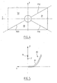
- These opaque bands are formed so as to obscure the radiation from arc 15 in two sectors angular well determined, in order to facilitate the formation by the mirror of the European cut beam normalized, delimited by a horizontal half-plane (on the side oncoming traffic) and through a half-plane going up to 15 ° above the horizontal (on the side of the roadside).
- two of the three half-planes transition radials between the three zones 21, 22, 23 of the mirror are located in the hidden areas cited above.
- transition half-plane P12 between zone 21 and zone 22 of the mirror is in this case inclined at + 25 ° above the horizontal, while the half-plane of transition P23 between zones 22 and 23 is inclined by 20 ° below the horizontal, on the side opposite to the lamp.
- a half transition plane P31 is tilted at -30 ° below the horizontal, on the same side as the P12 half-plane.
- the essential vocation of this area is to ensure the range of the crossover in a region located below and near the right half-cut, tilted, this in order to satisfactorily illuminate the right shoulder of the road at distances of the order of 40 meters and more.
- This area is defined by a base surface on which of the light spreading streaks are applied.
- the base surface is advantageously a portion of modified bottom dish, which is described in detail in document FR-A-2 609 148 in the name of the Applicant, to which we will refer for more details.
- the focal point F of these dishes is preferably located on the Y axis and offset backwards from the center, along Y, of arc 15. This axial offset is preferably between about 2 and 6 mm.
- the horizontal generator of such a surface base is a parabola with the same focal length and same focal point F, but the central part (bottom) of which is modified to ensure spoke convergence think about it.
- the configuration of this background part is determined so that the half angle of this convergence, and therefore of the divergence which follows in the distance, preferably around 20 °.
- the transition from modified part and the unmodified part is from preferably at a lateral distance of the order of 50 mm per relative to the optical axis.
- the modified central subzone of area 21 is used as is, i.e. it is a smooth, continuous and driftable surface (without indentations nor elbows).
- the purely parabolic outer subzone of the zone 21 extends between the central sub-zone 111 and the edge side of the mirror, and preferably receives a a number of slightly marked streaks intended to ensure controlled spreading of light especially along the inclined part of the standard cut and at favor lighting in the vicinity of the points of normalized measurement 75R and 50R of the projection screen.
- some of the streaks may present a non-symmetrical profile with a radius part of reduced curvature intended to ensure a large spread of light outwards and part of the radius of greater curvature intended to spread light little towards the inside.
- This zone is to generate the game e cut beam located below the half cut of left (horizontal) and perform a spread very important horizontal light, to give the beam the large width contributing to visual comfort.
- It preferably has a base surface which consists either of a portion of a self-generating surface horizontal cutoff, as defined in particular in FR-A-2,536,503, either by a portion of a horizontal self-generating cutting surface at bottom modified, as defined in document FR-A-2 609 148, or again by a portion of a self-generating surface horizontal cut-off, with intermediate zones modified, as defined in either of the documents FR-A-2 639 888 and FR-A-2 664 677. We are refer to the description of these documents for further details about the construction of the surfaces.
- the vertical sections of the surface are portions of dishes with evolving foci, so as to place all the source images below and flush with a horizontal cut defined by the horizontal axis of the projection screen.
- the sections verticals of the surface are parabolas. Their home is advantageously found shifted backwards with respect to the arc generated by the lamp.
- the horizontal generator of a such surface in the first case it is a parabola, in the second case of a parabola whose area background is changed to ensure convergence of the reflected radiation, and therefore at great distance a spreading, and in the third case of a parabola modified in its central zone by a set of zones successively divergent and / or convergent and / or satellite dishes.
- the base surface of zone 22 comprises, in its part left and from left to right in Figure 5 a first subzone whose horizontal generator is parabolic, a second subzone whose generator horizontal is changed to, from outside to inside, starting from a zero horizontal deviation, go through a point of maximum horizontal convergence and return to a point of zero horizontal deviation, and a third subzone including the horizontal generator is modified to go from outside to inside from said zero horizontal deviation, go through a point of maximum horizontal divergence and go back to a zero horizontal point of deviation located in the plane vertical axial YZ.
- Zone 22 also includes a specific streak, which we will describe below.
- the two border sub-areas, including the base surfaces are parabolas, each have a set of streaks with vertical guide intended to ensure large horizontal spread of light.
- these streaks may have profiles scalable so that streaks aligned vertically can be connected to each other without discontinuity, which avoids anomalies optics such as stray radiation dazzling.
- This area located in the lower part of the mirror between the transition planes P23 and P31, is advantageously a constructed surface like the surface of base of zone 22, namely in accordance with lessons from FR-A-2 664 677 and more particularly of its figure 11b.
- zone 23 does not have any streaks, so as to leave in the part of a beam generated a spot of concentration important in the axis of the road.
- the equation for area 23 is performed with identical value parameters or different from the parameters of zone 22.
- the basic focal distance of the surface of the zone 23 (parameter f 0 in the document FR-A-2 664 677) is less than that used for the zone 22.
- the axis of this surface corresponding to the axis 0x in FR-A-2 664 677, to be shifted downwards by a distance d relative to the axis Y common to the surfaces of the zones 21 and 22.
- the base focal point of the surface of zone 23 is located preferably, on the above offset axis, immediately in before said secondary source.
- the parameters of the area of the area 23 are preferably chosen such that, from the center towards the side edges of this area, the deviation horizontal outsourcing gradually increases in value zero at maximum divergence, then at convergence maximum, then at a deviation again zero at the level lateral parts with parabolic profile.
- the beam part generated by zone 23 has both a high concentration along the axis and a large spread contributing to visual comfort.
- the fact of moving back the arc 15 has for first effect of bringing it closer to focal point F of the zone 21 of the mirror, so that the parabolic-based subzone of this zone 21 will be able to generate a part of beam more concentrated in the distance, so that create the range of the driving beam.
- the cut generated by this zone in the first location of the arch is destroyed, since the images of the arc will project into positions no longer respecting this cut (and typically located on this one).
- FIGS. 11 and 12 roughly illustrate the areas of concentration of the passing beam and of the driving beam thus obtained. It is observed that, while the concentration of the passing beam is shifted towards the side of the road, and situated below the inclined half-cut c , the road beam is suitably centered on the axis of the route, materialized by point H in a standard projection screen.
- a lamp displacement with a simple obliquity that is to say with a direction of displacement of the arc 15 extending obliquely relative to to the Y axis in the YZ axial vertical plane of the mirror, can also prove satisfactory in some cases, and mainly in the case where the light of the two types of each time is centered horizontally on the axis of the road.
- the source remains located in the axial vertical plane of the mirror, so that when movement, the main beam focus area emitted will generally move vertically.
- this inclination is sufficiently limited so as not to cause a perceptible defect in the beam formed, especially since, conventionally, a arc has a greater thickness in the center than its ends.
- Such a tilt will not be bothersome either in the case where the source is constituted by a filament incandescent cylindrical.
- Figures 6 to 8 illustrate the case where the lamp 10 remains oriented in the conventional manner, i.e. with an AL lamp axis parallel to the Y axis from the mirror.
- the mobile support 16 ′ is in this case adapted and has a radial part 16a 'extending in a plane perpendicular to the axis AL of the lamp, and part cylindrical outer 16b 'whose axis AG is inclined at oblique to said axis AL and determines the direction displacement of the arc.
- the mirror and the guide structure 30 are identical to those of FIGS. 1 to 3, the sheath of guide 32 being aligned along the guide axis AG.
- the direction of movement of the source is oblique not only with respect in the horizontal XY plane, but also in relation to the plane vertical axial YZ, with corresponding behavior optics as described above.
- FIGS 9 and 10 illustrate another form of realization of the invention, in which the movement of the source is not real (the lamp is therefore fixed), but created by creating an offset image source during the interposition of one or more mobile dioptres between said source and at least part of the mirror 20.
- a diopter is provided so as to selectively intercept the radiation emitted by source 15 towards zone 21 of the mirror, the vocation is to generate the most concentrated part of the beam.
- This diopter 40 has a flat entry face 41, oriented vertically and parallel to the YZ plane, and a convex outlet face 42, determined so as to carry out the desired displacement of the arc.
- the diopter 40 in a conventional manner in itself, is guided by suitable guidance means and moved by a suitable actuator, these means not being shown.
- Face 42 is calculated such that the interposition of the diopter 40 creates an image source of the real source, designated by the reference 15 ', which occupies an identical position or close to the occupied position by the arc in the remote position of the lamp in the previous embodiments, as well shown Figures 9 and 10.
- the invention applies equally well to discharge lamp headlamps than lamp headlamps to filament. It also applies to generate beams other than a passing beam and a road beam.
Landscapes
- Engineering & Computer Science (AREA)
- General Engineering & Computer Science (AREA)
- Non-Portable Lighting Devices Or Systems Thereof (AREA)
Abstract
Description
- le miroir est fixe et les moyens de déplacement agissent sur la lampe.
- la lampe est montée dans un support mobile cylindrique coaxial avec la lampe, et des aménagements complémentaires de guidage en translation sont solidaires du miroir.
- lesdits aménagements complémentaires de guidage sont réalisés d'un seul tenant avec le miroir au cours de la fabrication de celui-ci par moulage, et la direction de démoulage du miroir est parallèle audit trajet oblique.
- la direction du trajet et l'axe de la lampe s'étendent en oblique par rapport à l'axe optique du miroir en étant contenus dans un plan vertical axial dudit miroir.
- la direction du trajet et l'axe de la lampe s'étendent en oblique à la fois par rapport à un plan horizontal axial et par rapport à un plan vertical axial du miroir.
- le miroir comporte une zone à base parabolique apte à engendrer une partie de concentration d'un premier faisceau située au-dessous d'une coupure donnée lorsque la source se trouve en avant d'un foyer de ladite base parabolique, et le déplacement de la source inclut un recul de celle-ci en direction dudit foyer.
- le mouvement de recul de la source s'accompagne d'un abaissement et d'un décalage latéral de la source, de manière à rediriger ladite partie de concentration du premier faisceau vers le haut et dans une direction latérale opposée, pour former la partie de concentration du second faisceau.
- le premier faisceau est un faisceau de croisement à concentration décalée vers le bas-côté de la route et le second faisceau est un faisceau de route à concentration axiale.
Claims (9)
- Projecteur de véhicule automobile, comprenant une source lumineuse (15) définie par une lampe (10), un miroir (20) et une glace, et des moyens de déplacement relatif de la lampe et du miroir entre deux positions stables pour engendrer dans ces positions respectivement un premier faisceau et un second faisceau de types différents, et dans lequel les moyens de déplacement opèrent par translation selon un trajet oblique par rapport à l'axe optique du miroir, caractérisé en ce que la lampe est orientée selon un axe (AL) parallèle à la direction dudit trajet oblique.
- Projecteur selon la revendication 1, caractérisé en ce que le miroir (20) est fixe et en ce que les moyens de déplacement agissent sur la lampe (10).
- Projecteur selon la revendication 2, caractérisé en ce que la lampe (10) est montée dans un support mobile cylindrique (16) coaxial avec la lampe, et en ce que des aménagements complémentaires de guidage en translation (30) sont solidaires du miroir (20).
- Projecteur selon la revendication 3, caractérisé en ce que lesdits aménagements complémentaires de guidage (30) sont réalisés d'un seul tenant avec le miroir (20) au cours de la fabrication de celui-ci par moulage, et en ce que la direction de démoulage du miroir est parallèle audit trajet oblique.
- Projecteur selon l'une des revendications 1 à 4, caractérisé en ce que la direction du trajet et l'axe (AL) de la lampe s'étendent en oblique par rapport à l'axe optique (Y) du miroir en étant contenus dans un plan vertical axial (YZ) dudit miroir.
- Projecteur selon l'une des revendications 1 à 4, caractérisé en ce que la direction du trajet et l'axe (AL) de la lampe s'étendent en oblique à la fois par rapport à un plan horizontal axial (XY) et par rapport à un plan vertical axial (YZ) du miroir.
- Projecteur selon la revendication 6, caractérisé en ce que le miroir (20) comporte une zone (21) à base parabolique apte à engendrer une partie de concentration d'un premier faisceau située au-dessous d'une coupure donnée lorsque la source (15) se trouve en avant d'un foyer (F) de ladite base parabolique, et en ce que le déplacement de la source (15) inclut un recul de celle-ci en direction dudit foyer.
- Projecteur selon la revendication 7, caractérisé en ce que le mouvement de recul de la source (15) s'accompagne d'un abaissement et d'un décalage latéral de la source, de manière à rediriger ladite partie de concentration du premier faisceau vers le haut et dans une direction latérale opposée, pour former la partie de concentration du second faisceau.
- Projecteur selon l'une des revendications 7 et 8, caractérisé en ce que le premier faisceau est un faisceau de croisement à concentration décalée vers le bas-côté de la route et le second faisceau est un faisceau de route à concentration axiale.
Applications Claiming Priority (2)
| Application Number | Priority Date | Filing Date | Title |
|---|---|---|---|
| FR9716135 | 1997-12-19 | ||
| FR9716135A FR2772883B1 (fr) | 1997-12-19 | 1997-12-19 | Projecteur de vehicule automobile a miroir unique et source deplacable pour engendrer deux faisceaux d'eclairage differents |
Publications (1)
| Publication Number | Publication Date |
|---|---|
| EP0926431A1 true EP0926431A1 (fr) | 1999-06-30 |
Family
ID=9514823
Family Applications (1)
| Application Number | Title | Priority Date | Filing Date |
|---|---|---|---|
| EP98403219A Withdrawn EP0926431A1 (fr) | 1997-12-19 | 1998-12-18 | Projecteur de véhicule automobile à miroir unique et source déplaçable pour engendrer deux faisceaux d'éclairage différents |
Country Status (2)
| Country | Link |
|---|---|
| EP (1) | EP0926431A1 (fr) |
| FR (1) | FR2772883B1 (fr) |
Cited By (7)
| Publication number | Priority date | Publication date | Assignee | Title |
|---|---|---|---|---|
| GB2342150B (en) * | 1998-09-30 | 2001-11-07 | Bosch Gmbh Robert | Headlight for vehicles |
| DE10247383A1 (de) * | 2002-10-10 | 2004-04-22 | Hella Kg Hueck & Co. | Scheinwerfer für Fahrzeuge |
| CZ297958B6 (cs) * | 2000-02-28 | 2007-05-09 | Autopal, S. R. O. | Svetlomet pro motorová vozidla |
| CN100453895C (zh) * | 2002-05-31 | 2009-01-21 | 三耀技术股份有限公司 | 车辆用前照灯 |
| EP2631534A3 (fr) * | 2012-02-22 | 2014-06-18 | Osram Sylvania Inc. | Phare de véhicule automobile comportant une source de lumière mobile pour créer des faisceaux différents |
| US10655807B2 (en) | 2018-08-29 | 2020-05-19 | Valeo North America, Inc. | Method and apparatus for vehicle lighting |
| CN112146056A (zh) * | 2019-06-28 | 2020-12-29 | 华域视觉科技(上海)有限公司 | 车灯照明装置、车辆前照灯及车辆 |
Citations (3)
| Publication number | Priority date | Publication date | Assignee | Title |
|---|---|---|---|---|
| US5142455A (en) * | 1991-06-05 | 1992-08-25 | General Electric Company | Vehicle headlamp in which multiple beams are derived from a single discharge-type light source |
| EP0705730A2 (fr) * | 1994-10-04 | 1996-04-10 | Robert Bosch Gmbh | Phare avec feux de route et codes pour véhicule |
| DE19741377A1 (de) * | 1996-09-20 | 1998-04-02 | Stanley Electric Co Ltd | Fahrzeug-Scheinwerfer |
-
1997
- 1997-12-19 FR FR9716135A patent/FR2772883B1/fr not_active Expired - Fee Related
-
1998
- 1998-12-18 EP EP98403219A patent/EP0926431A1/fr not_active Withdrawn
Patent Citations (3)
| Publication number | Priority date | Publication date | Assignee | Title |
|---|---|---|---|---|
| US5142455A (en) * | 1991-06-05 | 1992-08-25 | General Electric Company | Vehicle headlamp in which multiple beams are derived from a single discharge-type light source |
| EP0705730A2 (fr) * | 1994-10-04 | 1996-04-10 | Robert Bosch Gmbh | Phare avec feux de route et codes pour véhicule |
| DE19741377A1 (de) * | 1996-09-20 | 1998-04-02 | Stanley Electric Co Ltd | Fahrzeug-Scheinwerfer |
Cited By (8)
| Publication number | Priority date | Publication date | Assignee | Title |
|---|---|---|---|---|
| GB2342150B (en) * | 1998-09-30 | 2001-11-07 | Bosch Gmbh Robert | Headlight for vehicles |
| CZ297958B6 (cs) * | 2000-02-28 | 2007-05-09 | Autopal, S. R. O. | Svetlomet pro motorová vozidla |
| CN100453895C (zh) * | 2002-05-31 | 2009-01-21 | 三耀技术股份有限公司 | 车辆用前照灯 |
| DE10247383A1 (de) * | 2002-10-10 | 2004-04-22 | Hella Kg Hueck & Co. | Scheinwerfer für Fahrzeuge |
| EP2631534A3 (fr) * | 2012-02-22 | 2014-06-18 | Osram Sylvania Inc. | Phare de véhicule automobile comportant une source de lumière mobile pour créer des faisceaux différents |
| US10655807B2 (en) | 2018-08-29 | 2020-05-19 | Valeo North America, Inc. | Method and apparatus for vehicle lighting |
| CN112146056A (zh) * | 2019-06-28 | 2020-12-29 | 华域视觉科技(上海)有限公司 | 车灯照明装置、车辆前照灯及车辆 |
| WO2020258591A1 (fr) * | 2019-06-28 | 2020-12-30 | 华域视觉科技(上海)有限公司 | Dispositif d'éclairage de lampe de véhicule, phare de véhicule et véhicule |
Also Published As
| Publication number | Publication date |
|---|---|
| FR2772883B1 (fr) | 2000-03-10 |
| FR2772883A1 (fr) | 1999-06-25 |
Similar Documents
| Publication | Publication Date | Title |
|---|---|---|
| EP0581679B1 (fr) | Projecteur de véhicule automobile comportant une lampe à deux filaments pour engendrer sélectivement un faisceau antibrouillard et un faisceau de route | |
| EP0250284B1 (fr) | Projecteur de croisement sans coupelle à concentration décalée | |
| FR2536502A1 (fr) | Projecteur de croisement pour vehicule automobile | |
| EP0256930B1 (fr) | Projecteur antibrouillard à filament transversal pour véhicule automobile | |
| EP0250313B1 (fr) | Projecteur additionnel à un projecteur de croisement pour véhicule automobile | |
| FR2609148A1 (fr) | Projecteur de vehicule automobile comportant un reflecteur a surface complexe a fond modifie | |
| EP0628765B1 (fr) | Projecteur du genre elliptique pour véhicule automobile | |
| EP0684420B1 (fr) | Projecteur comportant une lampe à deux filaments pour engendrer un faisceau coupé et un faisceau non coupé | |
| FR2755748A1 (fr) | Projecteur de vehicule automobile, comportant une lampe a decharge a occulteurs et un reflecteur multi-zones | |
| EP0933585A1 (fr) | Projecteur à source transversale pour véhicule automobile susceptible d'émettre un faisceau à coupure nette | |
| FR2609146A1 (fr) | Projecteur de vehicule automobile comportant un reflecteur parabolique a fond modifie | |
| EP0926431A1 (fr) | Projecteur de véhicule automobile à miroir unique et source déplaçable pour engendrer deux faisceaux d'éclairage différents | |
| EP1600689A1 (fr) | Projecteur lumineux multifonction pour véhicule automobile | |
| FR2760070A1 (fr) | Projecteur comportant une lampe a deux filaments pour engendrer un faisceau coupe et un faisceau non coupe | |
| FR2583139A1 (fr) | Projecteur de croisement pour vehicule automobile | |
| EP0966633B1 (fr) | Projecteur du genre elliptique pour vehicule automobile | |
| EP1528313A2 (fr) | Projecteur pour véhicule automobile comportant une source lumineuse formée par une lampe à décharge. | |
| FR2793542A1 (fr) | Projecteur du genre elliptique a deux fonctions d'eclairage pour vehicule automobile | |
| FR2808867A1 (fr) | Projecteur bi-fonction a source lumineuse unique et occulteur mobile pour vehicule automobile | |
| FR2769687A1 (fr) | Ensemble de projecteurs gauche et droit de vehicule automobile, a proprietes photometriques ameliorees | |
| EP1096196A1 (fr) | Projecteur de véhicule, notamment projecteur de croisement, à encombrement réduit | |
| EP1400748A1 (fr) | Dispositif projecteur de véhicule automobile à miroir et élément de déviation conjugués avec coupure non plate | |
| EP0723109B1 (fr) | Projecteur de véhicule automobile comportant des moyens dioptriques interposés entre la source et le miroir | |
| FR2597575A1 (fr) | Reflecteur, notamment pour projecteur de vehicule automobile | |
| FR2789474A1 (fr) | Projecteur du genre elliptique pour vehicule automobile, susceptible d'engendrer selectivement l'un parmi deux types de faisceaux |
Legal Events
| Date | Code | Title | Description |
|---|---|---|---|
| PUAI | Public reference made under article 153(3) epc to a published international application that has entered the european phase |
Free format text: ORIGINAL CODE: 0009012 |
|
| AK | Designated contracting states |
Kind code of ref document: A1 Designated state(s): DE GB IT |
|
| AX | Request for extension of the european patent |
Free format text: AL;LT;LV;MK;RO;SI |
|
| 17P | Request for examination filed |
Effective date: 19991223 |
|
| AKX | Designation fees paid |
Free format text: DE GB IT |
|
| GRAP | Despatch of communication of intention to grant a patent |
Free format text: ORIGINAL CODE: EPIDOSNIGR1 |
|
| RIC1 | Information provided on ipc code assigned before grant |
Ipc: F21V 14/00 20060101ALI20070202BHEP Ipc: F21V 14/02 20060101AFI20070202BHEP |
|
| STAA | Information on the status of an ep patent application or granted ep patent |
Free format text: STATUS: THE APPLICATION IS DEEMED TO BE WITHDRAWN |
|
| 18D | Application deemed to be withdrawn |
Effective date: 20070713 |