EP0926438B1 - Aménagement des brûleurs à gaz pour une surface de cuisson - Google Patents
Aménagement des brûleurs à gaz pour une surface de cuisson Download PDFInfo
- Publication number
- EP0926438B1 EP0926438B1 EP98124269A EP98124269A EP0926438B1 EP 0926438 B1 EP0926438 B1 EP 0926438B1 EP 98124269 A EP98124269 A EP 98124269A EP 98124269 A EP98124269 A EP 98124269A EP 0926438 B1 EP0926438 B1 EP 0926438B1
- Authority
- EP
- European Patent Office
- Prior art keywords
- gas
- burner
- gas burner
- arrangement according
- burner arrangement
- Prior art date
- Legal status (The legal status is an assumption and is not a legal conclusion. Google has not performed a legal analysis and makes no representation as to the accuracy of the status listed.)
- Expired - Lifetime
Links
- 238000010411 cooking Methods 0.000 title claims description 11
- 230000007246 mechanism Effects 0.000 claims description 3
- 239000007789 gas Substances 0.000 description 68
- 239000000203 mixture Substances 0.000 description 5
- 238000010276 construction Methods 0.000 description 3
- 230000000712 assembly Effects 0.000 description 1
- 238000000429 assembly Methods 0.000 description 1
- 239000002737 fuel gas Substances 0.000 description 1
- 238000010438 heat treatment Methods 0.000 description 1
- 239000007788 liquid Substances 0.000 description 1
- 238000000034 method Methods 0.000 description 1
- 230000001105 regulatory effect Effects 0.000 description 1
Images


Classifications
-
- F—MECHANICAL ENGINEERING; LIGHTING; HEATING; WEAPONS; BLASTING
- F24—HEATING; RANGES; VENTILATING
- F24C—DOMESTIC STOVES OR RANGES ; DETAILS OF DOMESTIC STOVES OR RANGES, OF GENERAL APPLICATION
- F24C3/00—Stoves or ranges for gaseous fuels
- F24C3/08—Arrangement or mounting of burners
- F24C3/085—Arrangement or mounting of burners on ranges
-
- F—MECHANICAL ENGINEERING; LIGHTING; HEATING; WEAPONS; BLASTING
- F23—COMBUSTION APPARATUS; COMBUSTION PROCESSES
- F23D—BURNERS
- F23D14/00—Burners for combustion of a gas, e.g. of a gas stored under pressure as a liquid
- F23D14/02—Premix gas burners, i.e. in which gaseous fuel is mixed with combustion air upstream of the combustion zone
- F23D14/04—Premix gas burners, i.e. in which gaseous fuel is mixed with combustion air upstream of the combustion zone induction type, e.g. Bunsen burner
- F23D14/06—Premix gas burners, i.e. in which gaseous fuel is mixed with combustion air upstream of the combustion zone induction type, e.g. Bunsen burner with radial outlets at the burner head
- F23D14/065—Premix gas burners, i.e. in which gaseous fuel is mixed with combustion air upstream of the combustion zone induction type, e.g. Bunsen burner with radial outlets at the burner head with injector axis inclined to the burner head axis
Definitions
- the present invention relates to a gas burner arrangement with two in one Cooktop arranged symmetrically and with one each the gas supply to the Gas fittings influencing hotplates, their actuators from a control panel are brought out.
- Gas burner arrangements with two cooktops arranged symmetrically in a cooktop can - provided with a corresponding housing - part independent Appliances, but they can also be built-in cooktops in worktops in a kitchen unit be used.
- a gas fitting is assigned to each of the hotplates the operating elements that can be reached by operators, the gas supply to the hotplates and the ignition processes can be carried out.
- the individual Cooking the fuel gas from a common gas supply point locally, for example in the form of bottled liquid gas or as a central gas connection is realized, routed via physical pipelines and gas channels and available must be placed, it is necessary to meet these design constraints To take into account.
- the burner head of any hotplate it is possible to use the burner head of any hotplate to assign the gas valve assigned to it vertically to the operating front in order to both the To be able to design the burner unit and the gas fitting uniformly. But should the actuators for the gas fittings, for example, moved closer together than the associated hotplates, it is within the scope of the Arrangements required, either appropriately adapted different burner fitting units to be used or via a control rod or Cardan shafts that move from the actuators to correspondingly removed fittings lead to bring about distance adjustments.
- a gas burner arrangement with two arranged symmetrically in a hob Cooking areas that meet these requirements are according to the invention by the features of the claim 1 marked.
- gas burner arrangement with dual-circuit burners preferably characterized in that the gas-air mixture supply channels the gas burner for the gas supply to the ring-shaped external burner on the assigned Gas outlet opening of the associated gas fitting is arranged in a V-shape and that the gas supply lines for the gas supply to the internal burner from the Gas-air mixture supply pipes for the outer burner on the radially opposite side of the gas burner are aligned.
- a burner arrangement with a V-shaped arrangement gas-air mixture supply channels is from document GB-A-2 184 535 already known).
- the overall arrangement allows a very compact structure and the possibility of the actuators for the gas fittings are brought together close together in the center of the hob front to accommodate, the actuators sloping down towards the hob front are arranged. This is particularly advantageous in terms of operation and construction Cheap.
- the gas burner arrangement according to the invention characterized in that in addition to the actuators for influencing the Gas fittings other actuators for regulating the air intake through the Gas flowing in through the gas nozzle and thus the air supply in the area of the gas injector nozzle arrangement is arranged.
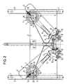
- gas burner assemblies 4 and associated gas fittings 5 for two hotplates On a base frame, consisting of two angle strips 2 equipped with feet 1 and an intermediate base board 3 are gas burner assemblies 4 and associated gas fittings 5 for two hotplates attached.
- the completely identical trained gas burner arrangements 4 each have two burner circuits, namely one Inner burner 6 and an outer burner 7 arranged around it, and are with its supply channel for the gas-air mixture intended for the external burner 7 V-shaped in the direction of the gas fittings 5.
- the vertical Level to the gas-air guide channel 8 for the external burner 7 is opposite in the lower area of the burner head of each of the gas burner arrangements 4 a connection provided for a gas output 9 starting from the respective fitting 5, the gas injector nozzle arrangement arranged in the burner head of the gas burner arrangement 4 10 leads.
- the gas coming from the valve 5 is passed through a gas nozzle 13, which is part of the fitting body, taking primary air blown.
- the intensive mixing of injected gas and suction Air to the external burner 7 is found in the gas-air supply duct 8 which is long enough instead of.
- an axially displaceable pipe socket 14 with an intake funnel 14 ' is assigned, over which the effective distance of the gas-air supply channel 8 to the nozzle 13 is changeable, whereby the air intake can also be changed.
- This pipe socket 14 can be actuated via an angle lever 15 mounted in the base plate by a rotary knob assembly 16, the - not shown - operating button protrudes from the control panel - also not shown.
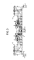
- the gas supply for the gas burner arrangements 4 of the two hotplates of the hob takes place centrally via a gas line 17 which is T-shaped between the two fittings 5 is connected to the two fittings 5.
- the two fittings 5 are constructed and arranged symmetrically to one another. They each contain three Gas channel branches, which have a rotary knob arrangement 18, which have a - not shown - open operating button protruding beyond the control panel and can be closed.
- One of the gas duct branches in the valve 5 is designed for constant gas throughput and the gas supply line 9 to Internal burner 6 assigned. After an initial rotary movement of the rotary toggle device 18, this gas channel branch is opened completely, for the whole further adjustment path of this rotary toggle device 18.
- an ignition electrode 20 is arranged in the vicinity of the inner burner 6.
- the ignition voltage for generating the ignition sparks is generated at the Embodiment according to FIGS. 1 and 5 with the aid of an ignition generator 21, which by one of the rotary toggle devices e.g. operable by axial pushing Contact 24 is activated or in the embodiment of FIGS. 2 and 4 by the Actuation of a piezo element on which the rotary toggle device 18 acts by prepared by the advance rotary movement or pushing-in movement of the Rotary toggle device at the time of opening of said gas channel branch a striking movement is exerted on the piezo element 25.
- thermocouple 22 is arranged over which - as long as the flame on the inner burner 6 is present - a main valve 23 is kept open for the gas outlet.
- the nozzle 13 and thus each of the gas burner arrangement 4 are assigned to the external burner 7.
- the flame of the inner burner 6 is ignited.
- One of the two assigned to the external burner 7 and to the gas nozzle 13 guided gas channel branches is variable with regard to the gas flow rate and can until the end of a predetermined angle of rotation of the rotary toggle device be completely closed.
- the second of the gas channel branches led to the gas nozzle 13 remains fully open during this time and is used for secure gas supply for the external burner 7 at minimum heating output.
- the design and arrangement of the gas burners for two hotplates is designed in this way and chosen that for simple and similar components for the both hotplate units can be used.
- the gas fittings 5 as well their associated adjustment mechanisms for the addition of air in the area of the nozzles 13 are mirror images and largely identical; the design of the Two-circuit gas burner arrangements 4 are completely identical. Nevertheless, it allows this Design that the actuators for the cooker areas apart are close together on the front panel and an operating block form.
Landscapes
- Engineering & Computer Science (AREA)
- Chemical & Material Sciences (AREA)
- Combustion & Propulsion (AREA)
- Mechanical Engineering (AREA)
- General Engineering & Computer Science (AREA)
- Gas Burners (AREA)
- Feeding And Controlling Fuel (AREA)
Claims (10)
- Agencement de brûleurs à gaz pour deux emplacements de cuisson disposés symétriquement dans une surface de cuisson, comprenant chacun une unité (4) de brûleur à gaz constituée d'un brûleur intérieur (6) et d'un brûleur annulaire extérieur (7), comprenant chacun un canal (8) d'amenée d'air et de gaz pour chacun des deux brûleurs extérieurs (7), un conduit de gaz (9) pour chacun des deux brûleurs intérieurs (6), et une robinetterie de gaz (5) pour chacune des deux unités (4) de brûleurs à gaz, dans lequel les deux unités (4) de brûleur à gaz ont des configurations identiques, les deux robinetteries de gaz (5) étant disposées plus près l'une de l'autre que les unités (4) de brûleur à gaz, les deux unités (4) de brûleurs à gaz avec leurs canaux (8) d'amenée d'air et de gaz sont disposées en forme de V sur des gicleurs de sortie de gaz et les robinetteries de gaz (5) rapprochées l'une de l'autre, un raccordement du conduit de gaz (9) étant prévu sur le côté de chaque unité (4) de brûleur à gaz respective qui est diamétralement opposé au canal (8) d'amenée d'air et de gaz.
- Agencement de brûleurs à gaz selon la revendication 1, caractérisé en ce que chacune des deux robinetteries de gaz (5) présente un gicleur (13) de sortie de gaz associé au canal (8) d'amenée d'air et de gaz.
- Agencement de brûleurs à gaz selon la revendication 2, caractérisé en ce que les deux gicleurs (13) de sortie de gaz sont orientés en V l'un par rapport à l'autre.
- Agencement de brûleurs à gaz selon l'une des revendications 1 à 3, caractérisé en ce qu'à chacune des deux robinetteries de gaz (5) est associé un organe d'actionnement (18) et en ce que les deux organes d'actionnement (18) sont disposés plus près l'un de l'autre que les unités (4) de brûleurs à gaz.
- Agencement de brûleurs à gaz selon l'une des revendications 1 à 4, caractérisé en ce que les deux robinetteries de gaz (5) ont des structures symétriques l'une par rapport à l'autre.
- Agencement de brûleurs à gaz selon l'une des revendications 2 à 5, caractérisé en ce qu'un mécanisme de réglage (14, 15) pour adapter l'apport d'air est disposé dans la zone du gicleur (13) de sortie de gaz.
- Agencement de brûleurs à gaz selon la revendication 6, caractérisé en ce que les mécanismes de réglage pour adapter l'apport d'air ont des configurations symétriques l'une par rapport à l'autre.
- Agencement de brûleurs à gaz selon la revendication 6 ou 7, caractérisé en ce que des organes d'actionnement (16) supplémentaires prévus pour l'adaptation de l'apport d'air sont disposés à côté des organes d'actionnement (18) des robinetteries de gaz (5).
- Surface de cuisson à gaz dotée de deux emplacements de cuisson disposés symétriquement et d'un agencement de brûleurs à gaz selon l'une des revendications 1 à 8, caractérisée en ce que les robinets de gaz (5) sont disposées dans une partie avant de la surface de cuisson à gaz.
- Surface de cuisson à gaz selon la revendication 9, caractérisée en ce que la surface de cuisson à gaz est configurée comme plaque de cuisson qui peut être encastrée dans une découpe d'un plan de travail.
Applications Claiming Priority (2)
| Application Number | Priority Date | Filing Date | Title |
|---|---|---|---|
| DE19757731 | 1997-12-23 | ||
| DE19757731A DE19757731A1 (de) | 1997-12-23 | 1997-12-23 | Gasbrenneranordnung für Kochstellen |
Publications (2)
| Publication Number | Publication Date |
|---|---|
| EP0926438A1 EP0926438A1 (fr) | 1999-06-30 |
| EP0926438B1 true EP0926438B1 (fr) | 2004-04-14 |
Family
ID=7853294
Family Applications (1)
| Application Number | Title | Priority Date | Filing Date |
|---|---|---|---|
| EP98124269A Expired - Lifetime EP0926438B1 (fr) | 1997-12-23 | 1998-12-18 | Aménagement des brûleurs à gaz pour une surface de cuisson |
Country Status (4)
| Country | Link |
|---|---|
| US (1) | US6425389B1 (fr) |
| EP (1) | EP0926438B1 (fr) |
| DE (2) | DE19757731A1 (fr) |
| ES (1) | ES2218751T3 (fr) |
Families Citing this family (5)
| Publication number | Priority date | Publication date | Assignee | Title |
|---|---|---|---|---|
| KR200180405Y1 (ko) * | 1999-11-24 | 2000-05-01 | 김충일 | 휴대용 가스렌지의 안전장치 |
| US20060054159A1 (en) * | 2004-09-16 | 2006-03-16 | Hosun Universal Co., Ltd. | Twin-nozzle gas switch for a barbeque grill |
| TWM315810U (en) * | 2006-12-22 | 2007-07-21 | Seven Universe Ind Co Ltd | Improvement of the gas burner set |
| DE102008014841B4 (de) * | 2008-03-07 | 2015-05-28 | E.G.O. Elektro-Gerätebau GmbH | Gasbrenner-Modul für ein Gaskochfeld sowie Gaskochfeld |
| JP2015230118A (ja) * | 2014-06-04 | 2015-12-21 | 株式会社ハーマン | ガスコンロ |
Family Cites Families (14)
| Publication number | Priority date | Publication date | Assignee | Title |
|---|---|---|---|---|
| US601039A (en) * | 1898-03-22 | of erie | ||
| US1456754A (en) * | 1922-07-14 | 1923-05-29 | Peolples Natural Gas Company | Gas burner |
| US1878143A (en) * | 1927-05-21 | 1932-09-20 | Roper Corp Geo D | Gas range |
| US1896082A (en) * | 1930-04-02 | 1933-02-07 | Philip S Harper | Burner |
| US2043382A (en) * | 1931-04-24 | 1936-06-09 | Borg Warner | Burner tray |
| US2781779A (en) * | 1952-01-26 | 1957-02-19 | W J Schoenberger Co | Gas range burner control |
| US3785364A (en) * | 1972-06-05 | 1974-01-15 | Columbia Gas Syst Service Corp | Smooth top range |
| US3843313A (en) * | 1973-07-23 | 1974-10-22 | Raytheon Co | Multi-cavity radiant burner |
| GB8519088D0 (en) * | 1985-07-29 | 1985-09-04 | Cannon Ind Ltd | Gas hotplates |
| GB2184535B (en) * | 1985-12-20 | 1989-09-13 | Ti New World Ltd | Improvements in or relating to hobs |
| US4889103A (en) * | 1988-01-25 | 1989-12-26 | Joseph Fraioli | Infrared wok heater |
| US4899723A (en) * | 1989-06-14 | 1990-02-13 | Industrias Fenix S.A. | Combination gas and electric stove with burner arrangement therefor |
| IT229035Y1 (it) * | 1992-04-07 | 1998-06-24 | Zanussi Elettrodomestici | Piano di cottura modulare |
| DE19505469C1 (de) * | 1995-02-17 | 1996-02-08 | Schott Glaswerke | Anordnung für die Zuführung von Primärluft zu einem atmosphärischen Gasbrenner über einer Kochplatte aus Glaskeramik |
-
1997
- 1997-12-23 DE DE19757731A patent/DE19757731A1/de not_active Withdrawn
-
1998
- 1998-12-18 DE DE59811195T patent/DE59811195D1/de not_active Expired - Fee Related
- 1998-12-18 ES ES98124269T patent/ES2218751T3/es not_active Expired - Lifetime
- 1998-12-18 EP EP98124269A patent/EP0926438B1/fr not_active Expired - Lifetime
- 1998-12-23 US US09/220,236 patent/US6425389B1/en not_active Expired - Fee Related
Also Published As
| Publication number | Publication date |
|---|---|
| DE59811195D1 (de) | 2004-05-19 |
| DE19757731A1 (de) | 1999-06-24 |
| ES2218751T3 (es) | 2004-11-16 |
| US6425389B1 (en) | 2002-07-30 |
| EP0926438A1 (fr) | 1999-06-30 |
Similar Documents
| Publication | Publication Date | Title |
|---|---|---|
| DE69001128T2 (de) | Gaskochmulde. | |
| DE2440701C3 (de) | Gasherd mit mehreren Kochstellen-Brennern | |
| DE4326945C2 (de) | Regeleinrichtung für die Gaszufuhr zu einer Gaskocheinrichtung mit unter einer durchgehenden Kochfläche angeordneten Gasstrahlungsbrennern | |
| DE69802211T2 (de) | Gasbrenner mit mehreren flammensektoren | |
| DE19500263A1 (de) | Kochapparat mit zumindest einem abgedeckten Kochfeld und einem Strahlungsbrenner-Aggregat | |
| EP0926438B1 (fr) | Aménagement des brûleurs à gaz pour une surface de cuisson | |
| DE102008014841B4 (de) | Gasbrenner-Modul für ein Gaskochfeld sowie Gaskochfeld | |
| EP0926446B1 (fr) | Aménagement des brûleurs à gaz pour une surface de cuisson | |
| DE10161154A1 (de) | Brenner für einen mit flüssigem Brennstoff betriebenen Kocher, vorzugsweise für einen Pflanzenölkocher | |
| DE69729755T2 (de) | Betätigungsvorrichtung für mehrventilgasbrenner | |
| EP0926437B1 (fr) | Aménagement des brûleurs à gaz pour une surface de cuisson | |
| EP3149406A2 (fr) | Soupape de régulation de gaz, table de cuisson et cuisinière à gaz | |
| EP0415049A2 (fr) | Arrangement de buse pour un brûleur à gaz | |
| DE3223108C2 (de) | Verdampfungsölbrenner | |
| DE19844551C2 (de) | Gaskochgerät | |
| EP0598214B1 (fr) | Table de cuisson vitro-céramique pour cuisinière à gaz | |
| DE60212285T2 (de) | Absperreinrichtung des Gasstroms in einem Gasgerät | |
| EP3012527A1 (fr) | Poste de cuisson et cuisiniere | |
| EP0097315B1 (fr) | Dispositif de brûleur à fuel pour fourneaux roulants | |
| DE102018103905B4 (de) | Zweikreis-Gaskochstelle und Verfahren zum Verhindern eines Düsenbrands bei einer Zweikreis-Gaskochstelle | |
| EP2567154B1 (fr) | Dispositif de réglage de gaz | |
| DE4427953A1 (de) | Gasbrenner für Kochstellen eines Gasherdes | |
| DE3102124A1 (de) | Gasherd mit oberflaechenbrenner | |
| DE814934C (de) | Niederdruck-Gasheizung, insbesondere fuer Kochherde | |
| DE3927159A1 (de) | Druckverdampferbrenner, insbesondere fuer feldkochherde |
Legal Events
| Date | Code | Title | Description |
|---|---|---|---|
| PUAI | Public reference made under article 153(3) epc to a published international application that has entered the european phase |
Free format text: ORIGINAL CODE: 0009012 |
|
| AK | Designated contracting states |
Kind code of ref document: A1 Designated state(s): DE ES FR GB IT NL |
|
| AX | Request for extension of the european patent |
Free format text: AL;LT;LV;MK;RO;SI |
|
| 17P | Request for examination filed |
Effective date: 19991217 |
|
| AKX | Designation fees paid |
Free format text: DE ES FR GB IT NL |
|
| 17Q | First examination report despatched |
Effective date: 20021104 |
|
| GRAP | Despatch of communication of intention to grant a patent |
Free format text: ORIGINAL CODE: EPIDOSNIGR1 |
|
| RAP1 | Party data changed (applicant data changed or rights of an application transferred) |
Owner name: BSH BOSCH UND SIEMENS HAUSGERAETE GMBH |
|
| GRAS | Grant fee paid |
Free format text: ORIGINAL CODE: EPIDOSNIGR3 |
|
| GRAA | (expected) grant |
Free format text: ORIGINAL CODE: 0009210 |
|
| AK | Designated contracting states |
Kind code of ref document: B1 Designated state(s): DE ES FR GB IT NL |
|
| REG | Reference to a national code |
Ref country code: GB Ref legal event code: FG4D Free format text: NOT ENGLISH |
|
| GBT | Gb: translation of ep patent filed (gb section 77(6)(a)/1977) |
Effective date: 20040401 |
|
| REF | Corresponds to: |
Ref document number: 59811195 Country of ref document: DE Date of ref document: 20040519 Kind code of ref document: P |
|
| ET | Fr: translation filed | ||
| REG | Reference to a national code |
Ref country code: ES Ref legal event code: FG2A Ref document number: 2218751 Country of ref document: ES Kind code of ref document: T3 |
|
| PLBE | No opposition filed within time limit |
Free format text: ORIGINAL CODE: 0009261 |
|
| STAA | Information on the status of an ep patent application or granted ep patent |
Free format text: STATUS: NO OPPOSITION FILED WITHIN TIME LIMIT |
|
| 26N | No opposition filed |
Effective date: 20050117 |
|
| PGFP | Annual fee paid to national office [announced via postgrant information from national office to epo] |
Ref country code: NL Payment date: 20081219 Year of fee payment: 11 |
|
| PGFP | Annual fee paid to national office [announced via postgrant information from national office to epo] |
Ref country code: ES Payment date: 20081219 Year of fee payment: 11 |
|
| PGFP | Annual fee paid to national office [announced via postgrant information from national office to epo] |
Ref country code: IT Payment date: 20081223 Year of fee payment: 11 |
|
| PGFP | Annual fee paid to national office [announced via postgrant information from national office to epo] |
Ref country code: FR Payment date: 20081216 Year of fee payment: 11 |
|
| PGFP | Annual fee paid to national office [announced via postgrant information from national office to epo] |
Ref country code: DE Payment date: 20081231 Year of fee payment: 11 |
|
| PGFP | Annual fee paid to national office [announced via postgrant information from national office to epo] |
Ref country code: GB Payment date: 20081219 Year of fee payment: 11 |
|
| REG | Reference to a national code |
Ref country code: NL Ref legal event code: V1 Effective date: 20100701 |
|
| GBPC | Gb: european patent ceased through non-payment of renewal fee |
Effective date: 20091218 |
|
| REG | Reference to a national code |
Ref country code: FR Ref legal event code: ST Effective date: 20100831 |
|
| PG25 | Lapsed in a contracting state [announced via postgrant information from national office to epo] |
Ref country code: NL Free format text: LAPSE BECAUSE OF NON-PAYMENT OF DUE FEES Effective date: 20100701 Ref country code: FR Free format text: LAPSE BECAUSE OF NON-PAYMENT OF DUE FEES Effective date: 20091231 |
|
| PG25 | Lapsed in a contracting state [announced via postgrant information from national office to epo] |
Ref country code: DE Free format text: LAPSE BECAUSE OF NON-PAYMENT OF DUE FEES Effective date: 20100701 |
|
| PG25 | Lapsed in a contracting state [announced via postgrant information from national office to epo] |
Ref country code: GB Free format text: LAPSE BECAUSE OF NON-PAYMENT OF DUE FEES Effective date: 20091218 |
|
| REG | Reference to a national code |
Ref country code: ES Ref legal event code: FD2A Effective date: 20110308 |
|
| PG25 | Lapsed in a contracting state [announced via postgrant information from national office to epo] |
Ref country code: IT Free format text: LAPSE BECAUSE OF NON-PAYMENT OF DUE FEES Effective date: 20091218 |
|
| PG25 | Lapsed in a contracting state [announced via postgrant information from national office to epo] |
Ref country code: ES Free format text: LAPSE BECAUSE OF NON-PAYMENT OF DUE FEES Effective date: 20110307 |
|
| PG25 | Lapsed in a contracting state [announced via postgrant information from national office to epo] |
Ref country code: ES Free format text: LAPSE BECAUSE OF NON-PAYMENT OF DUE FEES Effective date: 20091219 |