EP0926461A1 - Initiateur électro-pyrotechnique à trois connexions électriques - Google Patents
Initiateur électro-pyrotechnique à trois connexions électriques Download PDFInfo
- Publication number
- EP0926461A1 EP0926461A1 EP98403121A EP98403121A EP0926461A1 EP 0926461 A1 EP0926461 A1 EP 0926461A1 EP 98403121 A EP98403121 A EP 98403121A EP 98403121 A EP98403121 A EP 98403121A EP 0926461 A1 EP0926461 A1 EP 0926461A1
- Authority
- EP
- European Patent Office
- Prior art keywords
- resistive heating
- pins
- initiator
- heating elements
- initiator according
- Prior art date
- Legal status (The legal status is an assumption and is not a legal conclusion. Google has not performed a legal analysis and makes no representation as to the accuracy of the status listed.)
- Granted
Links
Images


Classifications
-
- F—MECHANICAL ENGINEERING; LIGHTING; HEATING; WEAPONS; BLASTING
- F42—AMMUNITION; BLASTING
- F42B—EXPLOSIVE CHARGES, e.g. FOR BLASTING, FIREWORKS, AMMUNITION
- F42B3/00—Blasting cartridges, i.e. case and explosive
- F42B3/10—Initiators therefor
- F42B3/103—Mounting initiator heads in initiators; Sealing-plugs
-
- B—PERFORMING OPERATIONS; TRANSPORTING
- B60—VEHICLES IN GENERAL
- B60R—VEHICLES, VEHICLE FITTINGS, OR VEHICLE PARTS, NOT OTHERWISE PROVIDED FOR
- B60R21/00—Arrangements or fittings on vehicles for protecting or preventing injuries to occupants or pedestrians in case of accidents or other traffic risks
- B60R21/02—Occupant safety arrangements or fittings, e.g. crash pads
- B60R21/16—Inflatable occupant restraints or confinements designed to inflate upon impact or impending impact, e.g. air bags
- B60R21/26—Inflatable occupant restraints or confinements designed to inflate upon impact or impending impact, e.g. air bags characterised by the inflation fluid source or means to control inflation fluid flow
- B60R21/264—Inflatable occupant restraints or confinements designed to inflate upon impact or impending impact, e.g. air bags characterised by the inflation fluid source or means to control inflation fluid flow using instantaneous generation of gas, e.g. pyrotechnic
- B60R21/2644—Inflatable occupant restraints or confinements designed to inflate upon impact or impending impact, e.g. air bags characterised by the inflation fluid source or means to control inflation fluid flow using instantaneous generation of gas, e.g. pyrotechnic using only solid reacting substances, e.g. pellets, powder
-
- B—PERFORMING OPERATIONS; TRANSPORTING
- B60—VEHICLES IN GENERAL
- B60R—VEHICLES, VEHICLE FITTINGS, OR VEHICLE PARTS, NOT OTHERWISE PROVIDED FOR
- B60R21/00—Arrangements or fittings on vehicles for protecting or preventing injuries to occupants or pedestrians in case of accidents or other traffic risks
- B60R21/02—Occupant safety arrangements or fittings, e.g. crash pads
- B60R21/16—Inflatable occupant restraints or confinements designed to inflate upon impact or impending impact, e.g. air bags
- B60R21/26—Inflatable occupant restraints or confinements designed to inflate upon impact or impending impact, e.g. air bags characterised by the inflation fluid source or means to control inflation fluid flow
- B60R2021/26029—Ignitors
-
- B—PERFORMING OPERATIONS; TRANSPORTING
- B60—VEHICLES IN GENERAL
- B60R—VEHICLES, VEHICLE FITTINGS, OR VEHICLE PARTS, NOT OTHERWISE PROVIDED FOR
- B60R21/00—Arrangements or fittings on vehicles for protecting or preventing injuries to occupants or pedestrians in case of accidents or other traffic risks
- B60R21/02—Occupant safety arrangements or fittings, e.g. crash pads
- B60R21/16—Inflatable occupant restraints or confinements designed to inflate upon impact or impending impact, e.g. air bags
- B60R21/26—Inflatable occupant restraints or confinements designed to inflate upon impact or impending impact, e.g. air bags characterised by the inflation fluid source or means to control inflation fluid flow
- B60R21/263—Inflatable occupant restraints or confinements designed to inflate upon impact or impending impact, e.g. air bags characterised by the inflation fluid source or means to control inflation fluid flow using a variable source, e.g. plural stage or controlled output
- B60R2021/2633—Inflatable occupant restraints or confinements designed to inflate upon impact or impending impact, e.g. air bags characterised by the inflation fluid source or means to control inflation fluid flow using a variable source, e.g. plural stage or controlled output with a plurality of inflation levels
Definitions
- the present invention relates to the field of pyrotechnic initiators and concerns more particularly an electro-pyrotechnic initiator intended for automobile safety.
- Electro-pyrotechnic initiators are traditionally made from two pins conductive of electricity which are maintained by a overmolding of insulating material and the ends of which are connected to each other by a filament resistive heater which is enclosed in a pearl and the lower ends of which are connected to a source of electrical current.
- Such electro-pyrotechnic initiators are widely used to build devices ignition of pyrotechnic gas generators intended to inflate protective cushions for occupants of a motor vehicle.
- the ignition devices for pyrotechnic generators adaptive and / or progressive gases i.e. generators which when coupled to systems appropriate detection, allow to adapt the flow and / or the volume of gas as a function of different parameters such as the nature and intensity of the shock, are generally made up of several initiators that each require power particular electric, which increases considerably the costs and the congestion.
- Patent application WO 97/16695 which relates to a adaptive pyrotechnic gas generator comprising two independent combustion chambers, discloses a single-ignition, single-plug initiator electric which allows to reduce costs and congestion.
- this initiator has two resistances separate incorporated in a switching bridge with four switches that can be toggled by torque and combined with a switching circuit produced by a diode circuit.
- the latter has two resistors different connected in parallel in a circuit electric.
- car manufacturers wish to be able, for security reasons, to control any time the value of each resistor included in the initiator by successive sendings of currents electrical tests generated using a box control electronics.
- each of the three electrical connections is constituted by a brooch.
- the two resistive heating elements are connected electrically to the pins via a means of transmission.
- the means of transmission consists of the two conductive metal rods extending each of the two ignition heads, the latter being preconstituted and remaining removable.
- the heads standard ignition systems that currently exist can be used.
- the means of transmission consists of the circuit comprising three conductive strips which are formed on the printed circuit support.
- the electrical circuit is partially covered with a layer of varnish insulating.
- each of the three electrical connections consists of a wire electric.
- Each of these three electrical wires can then present, on the one hand, a first end connected for example to one of the three connecting wires contained in an electric cable coming from the box control, and secondly, a second end connected, as before, to a metallic element hollow included in an overmolding or on a support printed circuit board on which three bands are formed conductive.
- the invention also relates to the use of a electro-pyrotechnic initiator according to the invention for cause the ignition of a pyrotechnic generator gas for occupants of a motor vehicle.
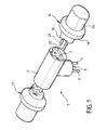
- Figure 1 is a perspective view of an electro-pyrotechnic initiator according to the first preferred embodiment of the invention.
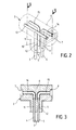
- FIG. 2 is a perspective view of the overmolding coating the three pins of the initiator shown in FIG. 1.
- FIG. 3 is a rear view in section along plane III-III containing the pins independent of the overmolding coating the three pins shown in FIG. 2.
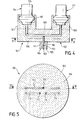
- Figure 4 is a front view, cut along IV-IV, of another electro-pyrotechnic initiator according to the first preferred embodiment of the invention.
- FIG. 5 is a bottom view, cut along VV, of the initiator shown in FIG. 4.
- Figure 6 is a perspective view of an electro-pyrotechnic initiator according to the second preferred embodiment of the invention.
- FIG. 7 is a sectional view along the median plane VII-VII of the initiator represented in FIG. 6.
- FIG. 8 is a front view, cut along line VIII-VIII, of another electro-pyrotechnic initiator according to the second preferred embodiment of the invention.
- FIG. 9 is a bottom view, cut along line IX-IX, of the initiator shown in FIG. 8.
- FIG. 10 is a bottom perspective view of the printed circuit support as well as the three conductive strips, the three pins and the two resistive heating elements which are included in the initiators shown in FIGS. 6 to 9.
- a 1 electro-pyrotechnic initiator consists of a 2-piece overmolding in adhesive resin based on hot melt polyamide that partially coats three pins 3 to 5 constituting the three connections of said initiator 1. More specifically, the overmolding 2 presents, on the one hand, a part elongated cylindrical 6 having a recess 7.8 to each of its ends, and on the other hand, a cylindrical external offset 9. Each of the three pins 3 to 5 breaks down respectively into a section solid metal 10 to 12 and in a metallic section hollow 13 to 15.
- each of the two metal elements solid 11 and 12 has a welded upper end at a first end of the hollow metallic element 14, 15 which corresponds to it, and the solid metal element 10 has an upper end welded to the body of the hollow metallic element 13.
- the lower end of each of the three solid metal elements 10 to 12, not included in the cylindrical external offset 9 of overmolding 2, is intended to be connected to a electrical supply means not shown on the figures.
- the hollow metal elements 13 to 15 are coated in the elongated cylindrical part 6 of the overmolding 2 and the recesses 7 and 8 of said elongated cylindrical part 6 of the overmolding 2 each contain one of the two ends of the hollow metallic element 13 and the second end of one of the two hollow metal elements 14 or 15. These ends are not covered by overmolding 2 and will, as described below, ensure the fixing the two ignition heads 16,17 in the overmolding 2.
- the two ignition heads 16, 17 are strictly identical to each other and therefore only one of the two ignition heads 16, 17 will be described. So the ignition head 16 is, conventionally, made up of from a base 18 containing a resistive element heater on which a load is placed thermosensitive, the latter being maintained by a fragmentable cap 24 secured to base 18.
- This thermosensitive charge advantageously decomposes, on the one hand, in a primary charge based on lead trinitroresorcinate, and on the other hand, in a reinforcing filler constituted by a mixture of powder boron / potassium nitrate and single powder type nitrocellulose base.
- the resistive heating element consists of a defined resistive heating strip by a printed sub-circuit as described in the patent US-A-5,544,585 or in its correspondent FR-A-2,704,944 the description of which is included, by reference, in the present description.
- the base 18 has a protrusion 19 which is itself extended by two metal rods 20.21 conductive. These two metal rods 20, 21 are to be inserted in both elements hollow metal 13 and 14 with open ends are contained in the recess 7 of the part cylindrical elongated 6, and the protrusion 19, by its special geometry, is designed to fit together perfectly in said recess 7.
- electro-pyrotechnic initiator 101 consists of from a 102-piece overmold in adhesive resin to partially hot-melt polyamide base three pins 103 to 105 constituting the three connections of said initiator 101. More specifically, the overmolding 102 has, on the one hand, a base 106 discoid, and on the other hand, two cylindrical projections 107 and 108 revealing a central recess 109.
- Each of the three pins 103 to 105 breaks down respectively in a solid metal section 110 to 112 and in a hollow metal section 113 to 115.
- each of two solid metal elements 111 and 112 have a upper end welded to a first end of the hollow metallic element 114, 115 which corresponds to it, and the solid metal element 110 has one end upper welded to the body of the hollow metal element 113.
- the lower end of each of the three elements solid metal 110 to 112, not included in the base 106 ovoid molding discoid 103, is intended to be connected to a power supply means not shown in the figures.
- the ignition head 116 includes a base 118 on which is fixed a fragmentable cap 124 and contains a resistive heating element as well as a thermosensitive charge.
- the base 118 includes a protuberance which is itself extended by two rods conductive metal. These are inserted in the two hollow metallic elements 113 and 114, the open ends are contained in the projection cylindrical 107, and the protrusion is perfectly nested in the cylindrical external recess of the cylindrical projection 107.
- This initiator 101 is more particularly intended to be integrated into a pyrotechnic generator gas whose combustion chambers are not coaxial. Indeed, the central recess 109 of the overmolding 102 facilitates the use of such a initiator 101 in a generator with two chambers are separated by a partition since the latter can be easily embedded in the indentation 109 central. Each of the two bedrooms combustion then contains one of the two heads 116 and 117.
- an initiator 201,301 electro-pyrotechnic according to the second mode of preferred embodiment of the invention consists of from a printed circuit support 401 having the shaped like a thin parallelepipedic card.
- this support 401 which is made of epoxy resin loaded with fibers of glass, includes a bottom face 402 and a face upper 403.
- Three separate conductive strips 404 at 406 of identical width and parallel to the most large edge of the support 401 are printed on the face lower 402, a first strip 404 being of length slightly less than that of the largest edge and the other two bands 405 and 406 being aligned.
- Each of the two conductive strips 405 and 406 is connected to the conductive strip 404 using an element resistive heating 407, 408 whose description has been made previously.
- Each of the three bands 404 to 406 is connected by solder to a pin 409 to 411 itself embedded in the support 401.
- the underside 402 of the support 401 is partially covered with a layer of varnish insulator, only the areas of support 401 in which, on the one hand, the two resistive elements heaters 407, 408 are fixed by gluing, and other hand, the three pins 404 to 406 are embedded, remaining uncovered.
- the support 401 includes holes 412, 413 facing each of the two resistive heating elements 407, 408.
- the initiator 201 is produced at from a 202 mono-block overmolding. This last has, on the one hand, an elongated cylindrical part 203 which coats the support 401 with the exception of the zones of fixing of the two resistive heating elements 407, 408, and on the other hand, an external offset cylindrical 204 which coats the three pins 409 to 411 over part of their length.
- Two ignition heads 211 and 212 are formed from the two orifices 412 and 413 which are each covered by a load primary 205, 206 itself immersed in a charge reinforcement 207, 208 contained in a cap 209, 210 fragmentable.
- Each open end of the two caps 209, 210 fragmentable is fixed, for example by crimping, in one of the two ends presented by the elongated cylindrical part 203 of the overmolding 202.
- the respective chemical compositions of the different charges used are identical to those described above.
- the initiator 301 is constituted at from a single-block 310 overmold in adhesive resin to base of hot-melt polyamide which completely coats the support 401, the three conductive strips 404 to 406 and the two resistive heating elements 407, 408. More precisely, the overmolding 310 has, on the one hand, a discoid base 311, and on the other hand, two projections cylindrical 312 and 313 revealing a central recess 314.
- the discoid base 311 coats the three pins 409 to 411 on part of their length and each of the two cylindrical projections 312, 313 contains an ignition head 302,303.
- thermosensitive filler decomposing on the one hand, into a primary charge 304, 305, and on the other hand, into a charge reinforcing agent 306, 307, the chemical compositions of these different charges being also identical to those described above.
- Two caps 308, 309 fragmentable which each enclose one of the two heat-sensitive fillers, have one end open against the support 401 and are each covered by the cylindrical projection 312, 313 which matches.
Landscapes
- Engineering & Computer Science (AREA)
- General Engineering & Computer Science (AREA)
- Physics & Mathematics (AREA)
- Fluid Mechanics (AREA)
- Mechanical Engineering (AREA)
- Air Bags (AREA)
- Testing Electric Properties And Detecting Electric Faults (AREA)
- Details Of Connecting Devices For Male And Female Coupling (AREA)
Abstract
Description
- En fonctionnement, le boítier de commande envoie un
ordre de mise à feu sous forme de signal électrique
en fermant :
- d'une part, l'interrupteur de la voie électrique du boitier de commande qui est connectée à la connexion électrique de l'initiateur commune aux deux éléments résistifs chauffants, si cet interrupteur n'était pas antérieurement fermé,
- et d'autre part, l'un des deux ou les deux interrupteurs relatifs aux deux autres voies électriques du boítier de commande. Par conséquent, selon que ces deux derniers interrupteurs sont ouverts ou fermés, il est possible d'initier soit une seule tête d'allumage au choix, soit les deux têtes d'allumage simultanément ou successivement. En effet, le signal électrique, qui peut être constitué par une décharge de capacité ou par un créneau de courant régulé, permet alors de chauffer par effet Joule le ou les éléments résistifs chauffants choisis qui eux-mêmes provoquent l'inflammation de la charge thermosensible qui leur correspond.
- En mode de non-activation pyrotechnique de
l'initiateur, le boítier de commande envoie des
signaux électriques tests successifs beaucoup plus
faibles qui permettent de tester les deux éléments
résistifs chauffants. Chacun de ces signaux
électriques test est obtenu par sécurité en fermant :
- d'une part, l'interrupteur de la voie électrique du boítier de commande qui est connectée à la connexion électrique de l'initiateur commune aux deux éléments résistifs chauffants,
- et d'autre part, l'interrupteur de la voie électrique du boítier de commande qui est connectée à la connexion électrique de l'initiateur reliée à l'élément résistif chauffant que l'on veut tester.
- L'utilisation d'un tel initiateur dans un générateur pyrotechnique adaptatif et/ou progressif de gaz approprié permet de réduire à la fois les coûts et les encombrements, d'une part, en raison de l'emploi d'une unique alimentation électrique, par exemple réalisée à l'aide d'un câble électrique renfermant trois fils de liaison, au lieu de deux alimentations électriques, et d'autre part, en raison de l'emploi d'éléments résistifs chauffants identiques permettant de réduire le nombre d'étapes nécessaires à l'assemblage de l'initiateur.
- Cet initiateur offre la possibilité d'être relié à un boítier électronique de commande déjà existant et bien connu de l'homme du métier. Il suffit pour cela de connecter chacune des trois connexions électriques de l'initiateur à une voie électrique distincte et indépendante dudit boítier électronique de commande. De plus, il est particulièrement avantageux de raccorder deux générateurs contenant chacun un tel initiateur à un même boítier électronique de commande. En effet, ce montage ne nécessite alors que trois couples de voie électrique au lieu de quatre, ce qui est le cas lorsque l'on utilise deux générateurs contenant chacun deux initiateurs à alimentations électriques séparées.
Claims (10)
- Initiateur (1,101,201,301) électro-pyrotechnique comportant deux têtes d'allumage (16 et 17, 116 et 117, 211 et 212, 302 et 303), caractérisé en ce que,i) chacune des deux têtes d'allumage (16 et 17, 116 et 117, 211 et 212, 302 et 303) renferme une charge thermosensible et un élément résistif chauffant (407, 408),ii) les deux éléments résistifs chauffants (407,408) sont incorporés dans un circuit électrique qui comporte trois connexions électriques, l'une étant commune aux deux éléments résistifs chauffants (407 et 408) et les deux autres étant chacune reliées à un seul des deux éléments résistifs chauffants (407,408),iii) les trois connexions électriques sont connectées à un moyen d'alimentation électrique provenant d'un boítier de commande.
- Initiateur selon la revendication 1, caractérisé en ce que chacune des trois connexions électriques est constituée par une broche (3,4,5,409,410,411).
- Initiateur selon la revendication 2, caractérisé en ce que le moyen d'alimentation électrique est constitué par un câble électrique contenant trois fils de liaison, chacune des trois broches (3,4,5,409,410,411) étant connectée à l'un des trois fils de liaison.
- Initiateur selon la revendication 3, caractérisé en ce que les trois fils de liaison sont insérés dans une pièce intermédiaire venant s'emboíter dans les trois broches (3,4,5,409,410,411).
- Initiateur selon l'une quelconque des revendications 2 à 4, caractérisé en ce que les deux éléments résistifs chauffants (407,408) sont reliés électriquement aux broches (3,4,5,409,410,411) par l'intermédiaire d'un moyen de transmission.
- Initiateur selon la revendication 5, caractérisé en ce que,i) chacune des trois broches (3,4,5) se décompose en un tronçon métallique plein (10,11,12) et en un tronçon métallique creux (13,14,15),ii) un surmoulage (2) enrobe partiellement les trois broches (3,4,5),iii) l'élément résistif chauffant contenu dans chacune des deux têtes d'allumage (16,17) est relié électriquement, par l'intermédiaire de deux tiges métalliques (20,21) conductrices qui prolongent ladite tête d'allumage, au tronçon métallique creux (13) de la broche (3) commune aux deux éléments résistifs chauffants et au tronçon métallique creux (14,15) de l'une des deux autres broches (4,5).
- Initiateur selon la revendication 5, caractérisé en ce que,i) le circuit électrique est intégré dans un circuit de trois bandes conductrices (404,405,406) qui sont formées sur un support (401) de circuit imprimé, chacune des trois bandes conductrices (404,405,406) étant connectée à l'une des trois broches (409,410,411),ii) les deux éléments résistifs chauffants (407 et 408) sont fixés dans le support (401) de circuit imprimé de façon à ce que l'une des trois bandes conductrices soit commune aux deux éléments résistifs chauffants (407 et 408) et de façon à ce que les deux autres bandes conductrices (405 et 406) soient chacune reliées à un seul des deux éléments résistifs chauffants (407,408),iii) chacun des deux éléments résistifs chauffants (407,408) est recouvert par la charge thermosensible qui lui correspond et qui est elle-même contenue dans un capuchon (209,210) fragmentable,iv) les deux capuchons (209 et 210) fragmentables sont solidarisés à un surmoulage (202) qui enrobe partiellement les trois broches (409,410,411) et le support (401) de circuit imprimé.
- Initiateur selon la revendication 7, caractérisé en ce que le circuit électrique est partiellement recouvert par une couche de vernis isolant.
- Initiateur selon la revendication 1, caractérisé en ce que chacune des trois connexions électriques est constituée par un fil électrique.
- Utilisation d'un initiateur électro-pyrotechnique selon l'une quelconque des revendications 1 à 9 pour provoquer l'allumage d'un générateur pyrotechnique de gaz pour occupants d'un véhicule automobile.
Applications Claiming Priority (2)
| Application Number | Priority Date | Filing Date | Title |
|---|---|---|---|
| FR9716217A FR2772909B1 (fr) | 1997-12-22 | 1997-12-22 | Initiateur electro-pyrotechnique a trois connexions electriques |
| FR9716217 | 1997-12-22 |
Publications (2)
| Publication Number | Publication Date |
|---|---|
| EP0926461A1 true EP0926461A1 (fr) | 1999-06-30 |
| EP0926461B1 EP0926461B1 (fr) | 2002-09-11 |
Family
ID=9514888
Family Applications (1)
| Application Number | Title | Priority Date | Filing Date |
|---|---|---|---|
| EP98403121A Expired - Lifetime EP0926461B1 (fr) | 1997-12-22 | 1998-12-10 | Initiateur électro-pyrotechnique à trois connexions électriques |
Country Status (8)
| Country | Link |
|---|---|
| US (1) | US6155171A (fr) |
| EP (1) | EP0926461B1 (fr) |
| JP (1) | JP2981226B2 (fr) |
| KR (1) | KR100312089B1 (fr) |
| BR (1) | BR9805705A (fr) |
| DE (1) | DE69807833T2 (fr) |
| ES (1) | ES2183304T3 (fr) |
| FR (1) | FR2772909B1 (fr) |
Cited By (3)
| Publication number | Priority date | Publication date | Assignee | Title |
|---|---|---|---|---|
| WO2003083403A1 (fr) * | 2002-03-28 | 2003-10-09 | Toyota Jidosha Kabushiki Kaisha | Amorceur |
| EP1205363A4 (fr) * | 1999-07-28 | 2005-03-30 | Nippon Kayaku Kk | Generateur de gaz |
| WO2012062262A3 (fr) * | 2010-10-15 | 2012-07-26 | Trw Airbag Systems Gmbh | Générateur de gaz et module coussin gonflable |
Families Citing this family (11)
| Publication number | Priority date | Publication date | Assignee | Title |
|---|---|---|---|---|
| FR2796715B1 (fr) * | 1999-07-19 | 2002-09-13 | Giat Ind Sa | Initiateur pyrotechnique et procede de montage d'un tel initiateur |
| DE29915056U1 (de) * | 1999-08-27 | 2000-01-27 | TRW Airbag Systems GmbH & Co. KG, 84544 Aschau | Zündereinheit für einen Gasgenerator |
| JP4426079B2 (ja) * | 1999-09-27 | 2010-03-03 | ダイセル化学工業株式会社 | イニシエータ組立体 |
| FR2813118B1 (fr) | 2000-08-17 | 2003-03-07 | Livbag Snc | Allumeur electro-pyrotechnique a deux tetes d'allumage et utilisation en securite automobile |
| ATE374709T1 (de) * | 2001-04-03 | 2007-10-15 | Nknm Ltd | Als einheit ausgeführter kopfstück/basis/kurzschlussbrücken-halter für einen mikrogasgenerator und diesen verwendender mikrogasgenerator |
| FR2853962B1 (fr) * | 2003-04-16 | 2006-06-16 | Snpe Materiaux Energetiques | Dispositif d'initiation electrique d'une micro-charge pyrotechnique et microsysteme utilisant un tel dispositif |
| DE102004010746A1 (de) * | 2003-04-30 | 2004-12-09 | Dynamit Nobel Ais Gmbh Automotive Ignition Systems | Gehäuse für ein pyromechanisches Trennelement mit integriertem Anzündelement |
| US7343859B2 (en) | 2003-11-10 | 2008-03-18 | Honda Motor Co., Ltd. | Squib |
| US9010803B2 (en) * | 2012-11-29 | 2015-04-21 | Autoliv Asp, Inc. | Duplex firing inflator |
| US9290419B2 (en) | 2012-11-29 | 2016-03-22 | Autoliv Asp, Inc. | Duplex actuation system for inflatable restraints |
| US8986046B2 (en) | 2012-11-29 | 2015-03-24 | Autoliv Asp, Inc. | Electrical harness assembly for duplex activation for motor vehicle restraint systems |
Citations (4)
| Publication number | Priority date | Publication date | Assignee | Title |
|---|---|---|---|---|
| US2386211A (en) * | 1942-06-20 | 1945-10-09 | Specialties Dev Corp | Electrically actuated cartridge |
| EP0119458A2 (fr) * | 1983-03-11 | 1984-09-26 | Hüls Troisdorf Aktiengesellschaft | Allumeur électrique |
| FR2704944A1 (fr) | 1993-05-05 | 1994-11-10 | Ncs Pyrotechnie Technologies | Initiateur électro-pyrotechnique. |
| WO1997016695A1 (fr) | 1995-10-30 | 1997-05-09 | Livbag S.N.C. | Generateur pyrotechnique de gaz, a debit adaptable, pour coussins de protection |
Family Cites Families (4)
| Publication number | Priority date | Publication date | Assignee | Title |
|---|---|---|---|---|
| US3426682A (en) * | 1967-04-27 | 1969-02-11 | Sidney A Corren | Exploding fuse |
| US4585955B1 (en) * | 1982-12-15 | 2000-11-21 | Tokyo Shibaura Electric Co | Internally regulated power voltage circuit for mis semiconductor integrated circuit |
| DE4140692A1 (de) * | 1991-12-10 | 1993-06-17 | Trw Repa Gmbh | Elektrische steckverbindung an einem mit elektrischem zuender versehenen pyrotechnischen gasgenerator |
| US6070531A (en) * | 1997-07-22 | 2000-06-06 | Autoliv Asp, Inc. | Application specific integrated circuit package and initiator employing same |
-
1997
- 1997-12-22 FR FR9716217A patent/FR2772909B1/fr not_active Expired - Fee Related
-
1998
- 1998-12-10 DE DE69807833T patent/DE69807833T2/de not_active Expired - Fee Related
- 1998-12-10 ES ES98403121T patent/ES2183304T3/es not_active Expired - Lifetime
- 1998-12-10 EP EP98403121A patent/EP0926461B1/fr not_active Expired - Lifetime
- 1998-12-18 KR KR1019980055967A patent/KR100312089B1/ko not_active Expired - Fee Related
- 1998-12-22 US US09/217,887 patent/US6155171A/en not_active Expired - Fee Related
- 1998-12-22 JP JP10364414A patent/JP2981226B2/ja not_active Expired - Fee Related
- 1998-12-22 BR BR9805705-7A patent/BR9805705A/pt not_active IP Right Cessation
Patent Citations (5)
| Publication number | Priority date | Publication date | Assignee | Title |
|---|---|---|---|---|
| US2386211A (en) * | 1942-06-20 | 1945-10-09 | Specialties Dev Corp | Electrically actuated cartridge |
| EP0119458A2 (fr) * | 1983-03-11 | 1984-09-26 | Hüls Troisdorf Aktiengesellschaft | Allumeur électrique |
| FR2704944A1 (fr) | 1993-05-05 | 1994-11-10 | Ncs Pyrotechnie Technologies | Initiateur électro-pyrotechnique. |
| US5544585A (en) | 1993-05-05 | 1996-08-13 | Ncs Pyrotechnie Et Technologies | Electro-pyrotechnical initiator |
| WO1997016695A1 (fr) | 1995-10-30 | 1997-05-09 | Livbag S.N.C. | Generateur pyrotechnique de gaz, a debit adaptable, pour coussins de protection |
Cited By (5)
| Publication number | Priority date | Publication date | Assignee | Title |
|---|---|---|---|---|
| EP1205363A4 (fr) * | 1999-07-28 | 2005-03-30 | Nippon Kayaku Kk | Generateur de gaz |
| WO2003083403A1 (fr) * | 2002-03-28 | 2003-10-09 | Toyota Jidosha Kabushiki Kaisha | Amorceur |
| US7357083B2 (en) | 2002-03-28 | 2008-04-15 | Toyota Jidosha Kabushiki Kaisha | Initiator |
| WO2012062262A3 (fr) * | 2010-10-15 | 2012-07-26 | Trw Airbag Systems Gmbh | Générateur de gaz et module coussin gonflable |
| US9452729B2 (en) | 2010-10-15 | 2016-09-27 | Trw Airbag Systems Gmbh | Gas generator and airbag module |
Also Published As
| Publication number | Publication date |
|---|---|
| EP0926461B1 (fr) | 2002-09-11 |
| ES2183304T3 (es) | 2003-03-16 |
| DE69807833T2 (de) | 2003-08-07 |
| US6155171A (en) | 2000-12-05 |
| BR9805705A (pt) | 1999-12-14 |
| FR2772909A1 (fr) | 1999-06-25 |
| DE69807833D1 (de) | 2002-10-17 |
| KR100312089B1 (ko) | 2002-02-28 |
| JP2981226B2 (ja) | 1999-11-22 |
| FR2772909B1 (fr) | 2000-01-28 |
| KR19990063181A (ko) | 1999-07-26 |
| JPH11241900A (ja) | 1999-09-07 |
Similar Documents
| Publication | Publication Date | Title |
|---|---|---|
| EP0926461B1 (fr) | Initiateur électro-pyrotechnique à trois connexions électriques | |
| EP1180659B1 (fr) | Allumeur électro-pyrotechnique à deux têtes d'allumage et utilisation en sécurité automobile | |
| EP1030159B1 (fr) | Allumeur électropyrotechnique à sécurité d'allumage renforcé | |
| EP1030158B1 (fr) | Allumeur électro-pyrotechnique à électronique integrée | |
| EP3459100B1 (fr) | Dispositif de coupure destiné à être relié à un circuit électrique | |
| FR2557689A1 (fr) | Initiateur pyrotechnique utilisant une prise coaxiale | |
| EP0711400B1 (fr) | Initiateur pyrotechnique | |
| CA2217399C (fr) | Initiateur electropyrotechnique, procede de realisation d'un tel initiateur et systeme de securite pour vehicule | |
| FR2738060A1 (fr) | Dispositif electro-explosif realise sur substrat | |
| EP0834716A1 (fr) | Microgénérateur pyrotechnique de gaz à prise bifilaire bloquée | |
| EP0803700B1 (fr) | Initiateur à prise bifilaire auto-bloquante pour générateurs pyrotechniques de gaz | |
| EP0863379B1 (fr) | Initiateur électro-pyrotechnique constitué autour d'un circuit imprimé complet | |
| EP3782790A1 (fr) | Procédé pour pièce de carrosserie comportant un film chauffant | |
| EP1839946A1 (fr) | Dispositif d'éclairage pour allume-cigare ou prise électrique multi-fonction | |
| FR3071659B1 (fr) | Dispositif de coupure pyrotechnique | |
| FR2875594A1 (fr) | Initiateur electro-pyrotechnique | |
| EP0076210B1 (fr) | Initiateur pyrotechnique électrique à effet Joule | |
| EP0923794B1 (fr) | Terminaison de cable electrique munie d'un filtre | |
| FR2807155A1 (fr) | Initiateur pyrotechnique pouvant etre equipe d'un composant electrique ou electronique et/ou d'un connecteur | |
| EP0755105B1 (fr) | Module de protection à signalisation de défaut et ensemble de raccordement à protection | |
| US6460465B1 (en) | Ignition device for triggering a restraining device | |
| FR3071657A1 (fr) | Dispositif de coupure pyrotechnique | |
| FR2911675A1 (fr) | Initiateur electro-pyrotechnique a commande magnetique | |
| FR2726124A1 (fr) | Boitier pour dispositif a semiconducteur | |
| JP2004271030A (ja) | ヘッダー装置及びそれを有する点火器及びガス発生器 |
Legal Events
| Date | Code | Title | Description |
|---|---|---|---|
| PUAI | Public reference made under article 153(3) epc to a published international application that has entered the european phase |
Free format text: ORIGINAL CODE: 0009012 |
|
| AK | Designated contracting states |
Kind code of ref document: A1 Designated state(s): DE ES FR GB IT SE |
|
| AX | Request for extension of the european patent |
Free format text: AL;LT;LV;MK;RO;SI |
|
| 17P | Request for examination filed |
Effective date: 19991230 |
|
| AKX | Designation fees paid |
Free format text: DE ES FR GB IT SE |
|
| 17Q | First examination report despatched |
Effective date: 20010125 |
|
| GRAG | Despatch of communication of intention to grant |
Free format text: ORIGINAL CODE: EPIDOS AGRA |
|
| GRAG | Despatch of communication of intention to grant |
Free format text: ORIGINAL CODE: EPIDOS AGRA |
|
| GRAH | Despatch of communication of intention to grant a patent |
Free format text: ORIGINAL CODE: EPIDOS IGRA |
|
| GRAH | Despatch of communication of intention to grant a patent |
Free format text: ORIGINAL CODE: EPIDOS IGRA |
|
| GRAA | (expected) grant |
Free format text: ORIGINAL CODE: 0009210 |
|
| AK | Designated contracting states |
Kind code of ref document: B1 Designated state(s): DE ES FR GB IT SE |
|
| REG | Reference to a national code |
Ref country code: GB Ref legal event code: FG4D Free format text: NOT ENGLISH |
|
| REF | Corresponds to: |
Ref document number: 69807833 Country of ref document: DE Date of ref document: 20021017 |
|
| GBT | Gb: translation of ep patent filed (gb section 77(6)(a)/1977) |
Effective date: 20021130 |
|
| REG | Reference to a national code |
Ref country code: ES Ref legal event code: FG2A Ref document number: 2183304 Country of ref document: ES Kind code of ref document: T3 |
|
| RAP2 | Party data changed (patent owner data changed or rights of a patent transferred) |
Owner name: LIVBAG S.N.C. |
|
| PLBE | No opposition filed within time limit |
Free format text: ORIGINAL CODE: 0009261 |
|
| STAA | Information on the status of an ep patent application or granted ep patent |
Free format text: STATUS: NO OPPOSITION FILED WITHIN TIME LIMIT |
|
| 26N | No opposition filed |
Effective date: 20030612 |
|
| REG | Reference to a national code |
Ref country code: FR Ref legal event code: TP |
|
| PGFP | Annual fee paid to national office [announced via postgrant information from national office to epo] |
Ref country code: SE Payment date: 20061206 Year of fee payment: 9 Ref country code: GB Payment date: 20061206 Year of fee payment: 9 |
|
| PGFP | Annual fee paid to national office [announced via postgrant information from national office to epo] |
Ref country code: DE Payment date: 20061207 Year of fee payment: 9 |
|
| PGFP | Annual fee paid to national office [announced via postgrant information from national office to epo] |
Ref country code: FR Payment date: 20061208 Year of fee payment: 9 |
|
| PGFP | Annual fee paid to national office [announced via postgrant information from national office to epo] |
Ref country code: IT Payment date: 20061231 Year of fee payment: 9 |
|
| PGFP | Annual fee paid to national office [announced via postgrant information from national office to epo] |
Ref country code: ES Payment date: 20070122 Year of fee payment: 9 |
|
| EUG | Se: european patent has lapsed | ||
| GBPC | Gb: european patent ceased through non-payment of renewal fee |
Effective date: 20071210 |
|
| PG25 | Lapsed in a contracting state [announced via postgrant information from national office to epo] |
Ref country code: SE Free format text: LAPSE BECAUSE OF NON-PAYMENT OF DUE FEES Effective date: 20071211 Ref country code: DE Free format text: LAPSE BECAUSE OF NON-PAYMENT OF DUE FEES Effective date: 20080701 |
|
| REG | Reference to a national code |
Ref country code: FR Ref legal event code: ST Effective date: 20081020 |
|
| PG25 | Lapsed in a contracting state [announced via postgrant information from national office to epo] |
Ref country code: GB Free format text: LAPSE BECAUSE OF NON-PAYMENT OF DUE FEES Effective date: 20071210 |
|
| REG | Reference to a national code |
Ref country code: ES Ref legal event code: FD2A Effective date: 20071211 |
|
| PG25 | Lapsed in a contracting state [announced via postgrant information from national office to epo] |
Ref country code: FR Free format text: LAPSE BECAUSE OF NON-PAYMENT OF DUE FEES Effective date: 20071231 Ref country code: ES Free format text: LAPSE BECAUSE OF NON-PAYMENT OF DUE FEES Effective date: 20071211 |
|
| PG25 | Lapsed in a contracting state [announced via postgrant information from national office to epo] |
Ref country code: IT Free format text: LAPSE BECAUSE OF NON-PAYMENT OF DUE FEES Effective date: 20071210 |