EP0926482A2 - Vorrichtung zur Abbildung fluoreszierender Teilchen - Google Patents
Vorrichtung zur Abbildung fluoreszierender Teilchen Download PDFInfo
- Publication number
- EP0926482A2 EP0926482A2 EP98310358A EP98310358A EP0926482A2 EP 0926482 A2 EP0926482 A2 EP 0926482A2 EP 98310358 A EP98310358 A EP 98310358A EP 98310358 A EP98310358 A EP 98310358A EP 0926482 A2 EP0926482 A2 EP 0926482A2
- Authority
- EP
- European Patent Office
- Prior art keywords
- bottom portion
- imaging
- vessel
- excitation light
- imaging vessel
- Prior art date
- Legal status (The legal status is an assumption and is not a legal conclusion. Google has not performed a legal analysis and makes no representation as to the accuracy of the status listed.)
- Withdrawn
Links
Images


Classifications
-
- G—PHYSICS
- G01—MEASURING; TESTING
- G01N—INVESTIGATING OR ANALYSING MATERIALS BY DETERMINING THEIR CHEMICAL OR PHYSICAL PROPERTIES
- G01N15/00—Investigating characteristics of particles; Investigating permeability, pore-volume or surface-area of porous materials
- G01N15/10—Investigating individual particles
- G01N15/14—Optical investigation techniques, e.g. flow cytometry
- G01N15/1429—Signal processing
- G01N15/1433—Signal processing using image recognition
-
- G—PHYSICS
- G01—MEASURING; TESTING
- G01N—INVESTIGATING OR ANALYSING MATERIALS BY DETERMINING THEIR CHEMICAL OR PHYSICAL PROPERTIES
- G01N15/00—Investigating characteristics of particles; Investigating permeability, pore-volume or surface-area of porous materials
- G01N15/10—Investigating individual particles
- G01N15/14—Optical investigation techniques, e.g. flow cytometry
- G01N15/1434—Optical arrangements
- G01N2015/1447—Spatial selection
-
- G—PHYSICS
- G01—MEASURING; TESTING
- G01N—INVESTIGATING OR ANALYSING MATERIALS BY DETERMINING THEIR CHEMICAL OR PHYSICAL PROPERTIES
- G01N15/00—Investigating characteristics of particles; Investigating permeability, pore-volume or surface-area of porous materials
- G01N15/10—Investigating individual particles
- G01N15/14—Optical investigation techniques, e.g. flow cytometry
- G01N2015/1486—Counting the particles
Definitions
- This invention relates to an apparatus for imaging fluorescent particles, and more particularly to an apparatus for imaging fluorescent particles such as leukocytes or the like stained with a fluorescent dye.
- platelet preparation and erythrocyte preparation are produced by extracting platelets and erythrocytes from whole blood. These platelet and erythrocyte preparations are each used for blood transfusions, and it is undesirable for either preparation to contain leukocytes. It is therefore important to be able to know how many leukocytes the preparations contain. Conventionally this is done by placing a sample platelet preparation in a NAGEOTTE chamber, staining with a fluorescent dye, projecting an excitation light onto the sample and counting leukocytes via a microscope. Specifically, a 50 microliter sample is taken from a 200 or 400 milliliter bag of platelet preparation, the leukocytes in the sample are counted and converted to a leukocytes count for the whole bag. This is a tiring, inefficient, time-consuming task that has to be done by skilled personnel.
- An apparatus has been proposed to enable leukocytes to be counted, instead, by staining the leukocytes with a fluorescent dye, illuminating the sample with an excitation light having predetermined wavelengths, using a CCD camera or the like to image the sample and then analyzing the images to obtain a count of the leukocytes.
- the solution containing the stained leukocytes also contains fluorescent dye that also emits fluorescent light.
- the contrast may worsen to the point that the leukocyte images become so buried in the background that they cannot be picked out, making it impossible to count the leukocytes.
- An object of the present invention is to provide an apparatus for imaging fluorescent particles that enables the fluorescent particles to be well imaged by reducing the effect of background light.
- the present invention provides an apparatus for imaging fluorescent particles stained with a fluorescent dye, comprising an imaging vessel for collecting and accommodating the fluorescent particles in a bottom portion thereof, means for generating an excitation light for exciting the fluorescent particles, illumination means for illuminating only a vicinity of the bottom portion of the imaging vessel by the excitation light, and means for obtaining images from below the bottom portion of the imaging vessel.
- a cover can be positioned to prevent the upper part of the imaging vessel from being illuminated by the excitation light, or the same effect can be obtained by using a cover with a slit-shaped aperture.
- the fluorescent particles can be illuminated even more effectively by using a cylindrical lens or the like to convert the thin excitation laser beam into a wide, flat beam in order to illuminate just the bottom portion of the vessel.
- the same effect can also be obtained by deflecting the excitation light along the bottom portion, or by projecting the excitation light via a bundle of optical fibers the exit end of which is arranged in a straight line.
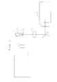
- Figure 1 is a block diagram showing the general configuration of an apparatus for imaging fluorescent particles according to the present invention.
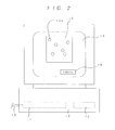
- Figure 2 is a front view of the apparatus used for analyzing and displaying obtained fluorescent particle images.
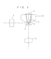
- Figure 3 is a diagram illustrating an arrangement of a cover used to shield the upper part of the imaging vessel.
- Figure 4 is a diagram illustrating another arrangement for shielding the upper part of the imaging vessel from illuminating light.
- Figure 5 is a diagram of an optical system used to form a strip-shaped excitation light beam.
- Figure 6 is a diagram of another optical system used to form a strip-shaped excitation light beam.
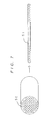
- Figure 7 is a diagram showing the configuration of optical elements used to form a strip-shaped excitation light beam.
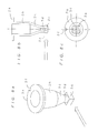
- Figure 8a is an exterior perspective view of the imaging vessel.
- Figure 8b is a cross-sectional view of the vessel.
- Figure 8c is a bottom view of the vessel.
- Figure 9 is a cross-sectional view of an imaging vessel according to another configuration.
- Figure 10 is a cross-sectional horizontal view of an imaging vessel according to yet another configuration.
- FIG. 1 shows the arrangement of a first embodiment of the present invention.
- reference numeral 1 denotes a laser light source, such as, for example, a YAG laser that produces a green laser beam.
- the laser beam from the laser light source 1 impinges upon, and is diffused by, a diffusion plate 2 comprised of ground glass or other such member that is able to diffuse light.
- the light thus diffused is projected at a bottom portion 3' of an imaging vessel 3, the upper part of which is covered by a cover 4.
- Fluorescent particles are accumulated in the bottom portion of the imaging vessel 3, and these fluorescent particles fluoresce when illuminated by the laser beam.
- the images of the fluorescent particles illuminated by the laser beam pass via a cover-glass 5 and objective lens 6 to a mirror 7 that reflects the images to a barrier filter 8 that transmits light in a prescribed frequency band, and are then picked up by a CCD camera 9.
- the images of the fluorescent particles picked up by the CCD camera 9 are passed via a signal line 10 to a video capture device 11 of a computer 12, where they are processed by an image processing circuit 13 ( Figure 2) to enable the fluorescent particles to be recognized.
- an image processing circuit 13 Figure 2
- Figure 2 depicts the image 15 of the bottom portion of the vessel together with a plurality of fluorescent particles 15a therein, displayed on the monitor 14.
- the fluorescent particles 15a are counted and the count is also displayed at the lower part 16 of the monitor 14.
- the imaging vessel 3 is molded in one piece from transparent polystyrene resin, glass, or acrylic resin, preferably polystyrene resin. Inserted into the imaging vessel 3 are a platelet preparation sample (100 microliters, for example), a chemical (Triton X) that dissolves platelet and leukocyte cytoplasm, and a fluorescent dye (propidium iodide) for staining leukocyte nuclei.
- the imaging vessel 3 is then subjected to centrifugal separation in a centrifuge (not shown), causing the leukocyte nuclei to collect in the bottom portion of the imaging vessel 3. All of the leukocyte nuclei can be collected in the bottom portion 3' of the imaging vessel 3 by applying a prescribed centrifugal force.
- the cover 4 is then used to cover the imaging vessel 3 in which the leukocyte nuclei stained with a fluorescent dye are collected in the bottom portion 3' thereof, and the imaging vessel 3 is mounted on the imaging apparatus.
- the laser light source 1 is activated, producing a laser beam which is diffused by the diffusion plate 2 and projected onto the bottom portion 3' of the imaging vessel 3.
- the nuclei of the leukocytes in the bottom portion 3' of the imaging vessel 3 have been stained with a fluorescent dye, when they are illuminated by the beam of excitation light, they emit fluorescent light having a frequency of around 600 nm. This is picked up via the cover-glass 5, objective lens 6, mirror 7 and barrier filter 8 below the imaging vessel 3.
- the barrier filter 8 only transmits light having the frequency of fluorescent light, allowing light of harmful frequencies to be blocked at this point.
- the laser beam is projected only at the bottom portion of the vessel, effectively illuminating the leukocytes collected there. Therefore, even if there is fluorescent dye floating in the solution in the imaging vessel 3, it is possible to prevent the fluorescent dye from forming harmful background light, thereby enabling the images to be obtained with improved contrast.
- the images of fluorescent particles thus obtained by the CCD camera 9 are passed via a signal line 10 to a video capture device 11 of a computer 12, where they are processed by an image processing circuit 13 to count the number of leukocytes 15a.
- the laser beam is projected only onto the bottom portion of the imaging vessel and does not illuminate the upper part of the vessel.
- the effect of only illuminating the bottom portion can be enhanced by providing a cover 20 that shields all parts other than the bottom portion from the illuminating light beam.
- an arrangement such as that shown in Figure 4 may be used.
- a mask 21 having a central slit-shaped aperture 21a is used.
- the laser beam from the laser light source 1 passes through the aperture 21a, ensuring that only the bottom portion 3' of the imaging vessel 3 is illuminated.
- FIG. 5 shows the type of arrangement that could be used in such a case, with laser beam 30 being shaped to a flat beam 33 by passage through cylindrical lenses 31 and 32, and the flat beam 33 being used to illuminate the bottom portion 3' of the imaging vessel 3.
- Figure 6 shows another arrangement, in which a scanning mirror 40 is used to deflect the laser beam 30, which passes through a lens 41 to scan the bottom portion of the imaging vessel.
- Figure 7 shows another arrangement, that uses a bundle of optical fibers.
- the fibers at the entrance end 50 from which the laser beam enters are arranged in a round configuration, while at the exit end 51 the fibers are arranged in a straight line, with the exit end 51 being disposed in the vicinity of the bottom portion of the imaging vessel so as to illuminate the bottom portion thereof.
- Figure 8 shows a preferred embodiment of the imaging vessel 3, preferably formed as a one-piece molding of polystyrene resin.
- the vessel has a ringshaped upper portion 3a having a notch 3f for positioning purposes.
- the imaging vessel 3 comprises a cylindrical portion 3b that extends vertically downward from the upper portion 3a to a small-diameter portion 3d, via a sloping portion 3c.
- a substantially square or rectangular block portion 3e is formed at the lower end.
- One side of the block portion 3e is arranged to be illuminated by a laser beam, indicated by the arrow.
- the imaging vessel 3 is attached to the apparatus, with the notch 3f being used to position the imaging vessel 3.
- a flat face of the block portion 3e is perpendicular to the direction of laser beam illumination, forming the entry surface for the incident beam.
- the laser beam illuminates only the bottom portion 3g of the imaging vessel 3.
- the bottom portion may also be illuminated by an arrangement such as the one shown in Figure 9, in which the block portion 3e has a round cross-section, and a negative cylindrical lens 60 is disposed on the side from which the bottom portion is illuminated by the excitation beam.
- a cover 70 is used to shield parts of the imaging vessel 3 other than the bottom portion from the laser beam.
- the cover 20, shown in Figure 3, on the imaging apparatus side may be omitted.
- the cover or shielding function may be realized by applying a light shield coating to the vessel, or by painting the vessel in a shielding color.
- fluorescent particles to be imaged are collected in the bottom portion of an imaging vessel, only that bottom portion is illuminated by an excitation light beam, and the bottom portion is imaged from below.
- background light is reduced, making it possible to obtain high-contrast images of the fluorescent particles, thereby making it possible to evaluate the images of the fluorescent particles and count them with greater precision.
Landscapes
- Chemical & Material Sciences (AREA)
- Life Sciences & Earth Sciences (AREA)
- Biochemistry (AREA)
- Dispersion Chemistry (AREA)
- Physics & Mathematics (AREA)
- Health & Medical Sciences (AREA)
- Engineering & Computer Science (AREA)
- Analytical Chemistry (AREA)
- Signal Processing (AREA)
- General Health & Medical Sciences (AREA)
- General Physics & Mathematics (AREA)
- Immunology (AREA)
- Pathology (AREA)
- Investigating, Analyzing Materials By Fluorescence Or Luminescence (AREA)
- Investigating Or Analysing Biological Materials (AREA)
Applications Claiming Priority (2)
| Application Number | Priority Date | Filing Date | Title |
|---|---|---|---|
| JP35641597 | 1997-12-25 | ||
| JP35641597A JP3731700B2 (ja) | 1997-12-25 | 1997-12-25 | 蛍光粒子撮像装置 |
Publications (2)
| Publication Number | Publication Date |
|---|---|
| EP0926482A2 true EP0926482A2 (de) | 1999-06-30 |
| EP0926482A3 EP0926482A3 (de) | 2001-09-26 |
Family
ID=18448904
Family Applications (1)
| Application Number | Title | Priority Date | Filing Date |
|---|---|---|---|
| EP98310358A Withdrawn EP0926482A3 (de) | 1997-12-25 | 1998-12-17 | Vorrichtung zur Abbildung fluoreszierender Teilchen |
Country Status (3)
| Country | Link |
|---|---|
| US (1) | US6252235B1 (de) |
| EP (1) | EP0926482A3 (de) |
| JP (1) | JP3731700B2 (de) |
Cited By (4)
| Publication number | Priority date | Publication date | Assignee | Title |
|---|---|---|---|---|
| WO2003040701A1 (en) * | 2001-11-02 | 2003-05-15 | Baker Hughes Incorporated | Method of particle characterization based on fluorescence imaging |
| WO2013177434A3 (en) * | 2012-05-24 | 2014-01-30 | Abbvie Inc | Systems and methods for detection of particles in a beneficial agent |
| CN105424668A (zh) * | 2015-12-22 | 2016-03-23 | 深圳先进技术研究院 | 一种荧光筛选系统 |
| WO2017200939A1 (en) * | 2016-05-16 | 2017-11-23 | Abbvie Inc. | Systems and methods for identifying protein aggregates in biotherapeutics |
Families Citing this family (6)
| Publication number | Priority date | Publication date | Assignee | Title |
|---|---|---|---|---|
| US6667177B1 (en) * | 1997-11-11 | 2003-12-23 | Kowa Company, Ltd. | Method for counting leukocytes and apparatus for counting leukocytes |
| US7966051B2 (en) | 2005-01-11 | 2011-06-21 | Olympus Corporation | Fluorescent agent concentration measuring apparatus, dose control apparatus, administration system, fluorescent agent concentration measuring method, and dose control method |
| JP4504207B2 (ja) * | 2005-01-11 | 2010-07-14 | オリンパス株式会社 | 蛍光剤集積濃度測定装置及び蛍光剤集積濃度測定方法 |
| US20060186346A1 (en) * | 2005-02-18 | 2006-08-24 | Academia Sinica | Method and system for reading microarrays |
| TWI582408B (zh) | 2011-08-29 | 2017-05-11 | 安美基公司 | 用於非破壞性檢測-流體中未溶解粒子之方法及裝置 |
| US10088660B2 (en) | 2017-02-10 | 2018-10-02 | Amgen Inc. | Imaging system for counting and sizing particles in fluid-filled vessels |
Family Cites Families (13)
| Publication number | Priority date | Publication date | Assignee | Title |
|---|---|---|---|---|
| USRE32598E (en) | 1975-12-11 | 1988-02-09 | Feature extraction system for extracting a predetermined feature from a signal | |
| FI64862C (fi) * | 1982-02-05 | 1984-01-10 | Kone Oy | Foerfarande foer fotometrisk maetning av vaetskor i reaktionskaerl och reaktionskaerl |
| JPS57201855A (en) * | 1982-04-08 | 1982-12-10 | Olympus Optical Co Ltd | Cuvette magazine for chemical analysis |
| JPH0660876B2 (ja) * | 1985-03-30 | 1994-08-10 | 株式会社東芝 | 分析装置 |
| ATE112181T1 (de) * | 1989-06-20 | 1994-10-15 | Claudio Bonini | Prüfröhrchen mit einer linsenförmigen aussenfläche, insbesondere für automatische klinische analysen. |
| GB8927742D0 (en) * | 1989-12-07 | 1990-02-07 | Diatec A S | Process and apparatus |
| US5225164A (en) | 1991-09-30 | 1993-07-06 | Astle Thomas W | Microplate laboratory tray with rectilinear wells |
| JP3187129B2 (ja) * | 1992-04-01 | 2001-07-11 | シスメックス株式会社 | 粒子分析装置 |
| US5319436A (en) | 1992-05-28 | 1994-06-07 | Packard Instrument Company, Inc. | Microplate farming wells with transparent bottom walls for assays using light measurements |
| US5355215A (en) | 1992-09-30 | 1994-10-11 | Environmental Research Institute Of Michigan | Method and apparatus for quantitative fluorescence measurements |
| US5424841A (en) * | 1993-05-28 | 1995-06-13 | Molecular Dynamics | Apparatus for measuring spatial distribution of fluorescence on a substrate |
| US6071748A (en) * | 1997-07-16 | 2000-06-06 | Ljl Biosystems, Inc. | Light detection device |
| US6097025A (en) * | 1997-10-31 | 2000-08-01 | Ljl Biosystems, Inc. | Light detection device having an optical-path switching mechanism |
-
1997
- 1997-12-25 JP JP35641597A patent/JP3731700B2/ja not_active Expired - Fee Related
-
1998
- 1998-12-17 US US09/213,763 patent/US6252235B1/en not_active Expired - Fee Related
- 1998-12-17 EP EP98310358A patent/EP0926482A3/de not_active Withdrawn
Cited By (13)
| Publication number | Priority date | Publication date | Assignee | Title |
|---|---|---|---|---|
| WO2003040701A1 (en) * | 2001-11-02 | 2003-05-15 | Baker Hughes Incorporated | Method of particle characterization based on fluorescence imaging |
| GB2397881A (en) * | 2001-11-02 | 2004-08-04 | Baker Hughes Inc | Method of particle characterization based on fluorescence imaging |
| GB2397881B (en) * | 2001-11-02 | 2005-07-06 | Baker Hughes Inc | Method of particle characterization based on fluorescence imaging |
| US7050166B2 (en) | 2001-11-02 | 2006-05-23 | Baker Hughes Incorporated | Calcium carbonate imaging technique |
| AU2002350098B2 (en) * | 2001-11-02 | 2007-10-25 | Baker Hughes Incorporated | Calcium carbonate imaging technique |
| AU2002350098C1 (en) * | 2001-11-02 | 2008-05-08 | Baker Hughes Incorporated | Calcium carbonate imaging technique |
| WO2013177434A3 (en) * | 2012-05-24 | 2014-01-30 | Abbvie Inc | Systems and methods for detection of particles in a beneficial agent |
| CN104487816A (zh) * | 2012-05-24 | 2015-04-01 | 艾伯维公司 | 用于检测有益制剂中的颗粒的系统及方法 |
| US10126226B2 (en) | 2012-05-24 | 2018-11-13 | Abbvie Inc. | Systems for inspection of protein particles in a liquid beneficial agent |
| US10132736B2 (en) | 2012-05-24 | 2018-11-20 | Abbvie Inc. | Methods for inspection of protein particles in a liquid beneficial agent |
| EP3835753A3 (de) * | 2012-05-24 | 2021-09-22 | AbbVie Inc. | Systeme und verfahren zum nachweis von teilchen in einem heilmittel |
| CN105424668A (zh) * | 2015-12-22 | 2016-03-23 | 深圳先进技术研究院 | 一种荧光筛选系统 |
| WO2017200939A1 (en) * | 2016-05-16 | 2017-11-23 | Abbvie Inc. | Systems and methods for identifying protein aggregates in biotherapeutics |
Also Published As
| Publication number | Publication date |
|---|---|
| JP3731700B2 (ja) | 2006-01-05 |
| JPH11183382A (ja) | 1999-07-09 |
| EP0926482A3 (de) | 2001-09-26 |
| US6252235B1 (en) | 2001-06-26 |
Similar Documents
| Publication | Publication Date | Title |
|---|---|---|
| US6211953B1 (en) | Vessel for imaging fluorescent particles | |
| EP0713086B1 (de) | Vorrichtung und Verfahren zum Erkennen und Zählen von selten vorkommenden Säugerzellen | |
| RU2402006C1 (ru) | Устройство, способ и компьютерная программа для измерений | |
| US5422712A (en) | Apparatus for measuring fluorescent spectra of particles in a flow | |
| US6249341B1 (en) | Imaging and analyzing parameters of small moving objects such as cells | |
| Dietz et al. | Volumetric capillary cytometry: a new method for absolute cell enumeration | |
| US4393466A (en) | Method of analyzing particles in a dilute fluid sample | |
| US5428451A (en) | Process and apparatus for counting particles | |
| EP2024893B1 (de) | Laserbeleuchtungssystem in einem fluoreszenzmikroskop | |
| CA2026617C (en) | Method and apparatus for measuring multiple optical properties of biological specimens | |
| US6671044B2 (en) | Imaging and analyzing parameters of small moving objects such as cells in broad flat flow | |
| US11041756B2 (en) | Method and apparatus of filtering light using a spectrometer enhanced with additional spectral filters with optical analysis of fluorescence and scattered light from particles suspended in a liquid medium using confocal and non confocal illumination and imaging | |
| US6252235B1 (en) | Apparatus for imaging fluorescent particles | |
| JPH08320285A (ja) | 粒子分析装置 | |
| JPH05180751A (ja) | 粒子画像分析装置 | |
| JP2021535373A (ja) | 表面色及び液体接触角の撮像方法 | |
| Deutsch et al. | Apparatus for high‐precision repetitive sequential optical measurement of living cells | |
| JP2007502419A (ja) | 時間遅延積分による対象を撮像するための装置および方法 | |
| EP1221607A1 (de) | Vorrichtung zum abbilden von fluoreszierenden teilchen | |
| AU2001211994B2 (en) | Imaging and analyzing parameters of small moving objects such as cells | |
| RU2092810C1 (ru) | Способ нанесения пробы суспензии для исследования частиц и способ определения размеров и числа частиц в суспензии | |
| Baak et al. | Equipment for quantitative microscopy | |
| JPH0815256A (ja) | フロ−式粒子画像解析装置 | |
| JPH075093A (ja) | フロー式粒子画像解析装置 | |
| WO2025120470A1 (en) | Varying spatial coherence in a microscope system |
Legal Events
| Date | Code | Title | Description |
|---|---|---|---|
| PUAI | Public reference made under article 153(3) epc to a published international application that has entered the european phase |
Free format text: ORIGINAL CODE: 0009012 |
|
| AK | Designated contracting states |
Kind code of ref document: A2 Designated state(s): AT BE CH CY DE DK ES FI FR GB GR IE IT LI LU MC NL PT SE Kind code of ref document: A2 Designated state(s): BE CH DE FR GB IT LI NL SE |
|
| AX | Request for extension of the european patent |
Free format text: AL;LT;LV;MK;RO;SI |
|
| PUAL | Search report despatched |
Free format text: ORIGINAL CODE: 0009013 |
|
| AK | Designated contracting states |
Kind code of ref document: A3 Designated state(s): AT BE CH CY DE DK ES FI FR GB GR IE IT LI LU MC NL PT SE |
|
| AX | Request for extension of the european patent |
Free format text: AL;LT;LV;MK;RO;SI |
|
| RIC1 | Information provided on ipc code assigned before grant |
Free format text: 7G 01N 21/03 A, 7G 01N 15/02 B |
|
| 17P | Request for examination filed |
Effective date: 20020218 |
|
| AKX | Designation fees paid |
Free format text: BE CH CY DE DK ES FI FR GB GR IE IT LI LU MC NL PT SE |
|
| RBV | Designated contracting states (corrected) |
Designated state(s): BE CH DE FR GB IT LI NL SE |
|
| 17Q | First examination report despatched |
Effective date: 20040603 |
|
| STAA | Information on the status of an ep patent application or granted ep patent |
Free format text: STATUS: THE APPLICATION IS DEEMED TO BE WITHDRAWN |
|
| 18D | Application deemed to be withdrawn |
Effective date: 20041014 |