EP0926509A1 - Akustisches Standortmesssystem - Google Patents
Akustisches Standortmesssystem Download PDFInfo
- Publication number
- EP0926509A1 EP0926509A1 EP98310586A EP98310586A EP0926509A1 EP 0926509 A1 EP0926509 A1 EP 0926509A1 EP 98310586 A EP98310586 A EP 98310586A EP 98310586 A EP98310586 A EP 98310586A EP 0926509 A1 EP0926509 A1 EP 0926509A1
- Authority
- EP
- European Patent Office
- Prior art keywords
- distance
- signal
- sonic
- receiver
- transmitter
- Prior art date
- Legal status (The legal status is an assumption and is not a legal conclusion. Google has not performed a legal analysis and makes no representation as to the accuracy of the status listed.)
- Granted
Links
Images


Classifications
-
- B—PERFORMING OPERATIONS; TRANSPORTING
- B66—HOISTING; LIFTING; HAULING
- B66B—ELEVATORS; ESCALATORS OR MOVING WALKWAYS
- B66B1/00—Control systems of elevators in general
- B66B1/34—Details, e.g. call counting devices, data transmission from car to control system, devices giving information to the control system
- B66B1/3492—Position or motion detectors or driving means for the detector
-
- G—PHYSICS
- G01—MEASURING; TESTING
- G01S—RADIO DIRECTION-FINDING; RADIO NAVIGATION; DETERMINING DISTANCE OR VELOCITY BY USE OF RADIO WAVES; LOCATING OR PRESENCE-DETECTING BY USE OF THE REFLECTION OR RERADIATION OF RADIO WAVES; ANALOGOUS ARRANGEMENTS USING OTHER WAVES
- G01S11/00—Systems for determining distance or velocity not using reflection or reradiation
- G01S11/14—Systems for determining distance or velocity not using reflection or reradiation using ultrasonic, sonic or infrasonic waves
Definitions
- This invention relates to a position measurement system and more particularly to a sonic position measurement system.
- the operation of a elevator depends on accurate and reliable position and speed information. This information is used to control the motion of the elevator as well as certain safety roles and operations, such as opening of the doors.
- Modern elevators use a high-resolution position information from a source such as an incremental encoder on a motor to control the speed profile.
- a source such as an incremental encoder on a motor
- safety-relevant functions they rely on additional discrete switches in the hoistway.
- One way to implement a high-resolution measurement of the elevator car's position in the hoistway is to use the sonic position sensor discussed hereinbefore.
- the measurement ultrasonic pulse is launched along a wire from the car to the receivers at the bottom and top of the hoistway. From the difference of the reception times, the position of the car is calculated.
- Objects of the invention include provision of a sonic position measurement system which is fault-tolerant and accurate over temperature.
- a method for measuring the position of an object includes: (a) transmitting a sonic signal by a transmitter connected to the object; (b) receiving said sonic signal at a first receiver, located a first distance from said transmitter; (c) receiving said sonic signal at a second receiver located a second distance from said transmitter and on an opposite side of said transmitter from said first receiver; (d) calculating a first distance between said transmitter and said first receiver; (e) calculating a second distance between said transmitter and said second receiver; and (f) calculating a total measured distance between said first receiver and said second receiver as the sum of said first distance and said second distance.
- the invention represents a significant improvement over the prior art sonic position measurement systems by adding an additional signal to indicate when the sonic pulse is transmitted, thereby allowing the system to detect a damaged or altered signal path (e.g., a mechanical displacement of a receiver, a loose sonic wire, or a change in the length of the sonic wire), or by irregular pulses coupled into the signal path by an outside source.
- a damaged or altered signal path e.g., a mechanical displacement of a receiver, a loose sonic wire, or a change in the length of the sonic wire
- the present invention provides a reference condition of the distance between the receivers, which is used by the system to compensate for the expansion and contraction of a building or other inaccuracies caused by temperature variations.
- the invention may be used as a position measurement (or reference) system for an elevator in a hoistway or for detecting the position of any object that moves along a predetermined path.
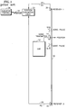
- a prior art position sensing system comprises an elevator car 12 having a sonic transmitter 14 (or signal coupler) connected thereto.
- the transmitter 14 generates a sound signal (or pulse) 16 at a predetermined rate and couples the sonic pulse to a sound signal conductor 18 (or wire) which is held or clamped at both ends by a clamping device (not shown).
- the sonic pulse 16 propagates away from the transmitter 14 in both directions along the wire 18 and is received at sonic receivers 20, 22 located at opposite sides of the transmitter 14 along the wire 18.
- the receivers 20, 22 receive the sonic pulse 16 they each transmit a electrical pulse R1, R2 on lines 24, 26, respectively, to a evaluation circuit (or logic) 30.
- the logic 30 comprises the necessary hardware (e.g., a microprocessor, analogue or digital circuits) and/or software necessary to perform the functions described herein.
- the logic 30 measures the time difference Td between the arrival of the two pulses 16 at the receivers 20, 22.
- the logic 30 computes the position of the elevator based on the time difference Td and the known speed of sound in the wire 18, and provides a position signal on a line 32 to an elevator controller 34.
- Td may be converted to a distance (by the speed of sound) which is indicative of the distance from the midpoint between the receivers, the direction from the midpoint is based on the sign of Td. If the time Td is zero, the transmitter is located mid-way between the two receivers 20, 22.
- European patent application EP 0,694,792 A1 published January 31, 1996 filed July 21, 1995.
- the position reference system of the present invention is similar to the system of Fig. 1, but adds a signal TS from the transmitter 14, which is provided on a line 36 to an evaluation circuit (or logic) 40 (which replaces the evaluation logic 30 of Fig. 1).
- the logic 40 comprises the hardware and/or software necessary to perform the functions described herein.
- the transmitter 14 provides the electrical signal (or pulse) TS on the line 36 when the sonic pulse 16 is launched (or sent) into the wire 18.
- the signal TS allows the measurement of the absolute distance from the transmitter 14 to each of the receivers 20, 22 via the measured flight times and the known speed of the sonic pulse 16, thereby providing two independent measurements of the position of the car in the hoistway.
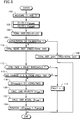
- the evaluation logic 40 enters at a step 100 which calculates the time T1 between the pulses TS and R1, and the time T2 between the pulses TS and R2.
- a series of steps 102 calculate D1 and D2 based on T1 and T2 and the known speed of sound Vsound in the wire 18.
- a step 104 calculates a Total Distance (TD) equal to the sum of D1 and D2.
- a step 106 determines whether the system is in initialization or calibration mode. If in calibration or initialization, TD is saved as a Total Reference Distance (TRD). If not in calibration or initialization, TD is saved as a Total Measured Distance (TMD).
- TRD Total Reference Distance
- TMD Total Measured Distance
- TMD When the system is in normal measurement operation, the value of TMD is updated at a predetermined rate, e.g., each time position is calculated. All predefined positions in the hoistway, e.g. floor levels, etc., are related to TMD and/or TRD.
- a step 112 compares TMD to TRD, and if the difference between TMD and TRD is greater than a predetermined fault threshold, e.g., 8 mm, a step 114, sets a Fault flag to one which is provided to the control 34 on a line 42.
- a predetermined fault threshold e.g. 8 mm
- a step 114 sets a Fault flag to one which is provided to the control 34 on a line 42.
- Other fault thresholds may be used.
- a step 116 checks whether the change in TMD is greater than a predetermined amount (x%), e.g., 50%, from the previous value of TMD. Other percent changes may be used if desired. If it is, the step 114 sets the Fault flag to one which is provided to the control 34 on the line 42.
- a step 118 compensates for temperature variations by calculating a scaled value of D1 as D1 SCALED by multiplying D1 by a scale factor TRD/TMD.
- D1 SCALED is equal to the absolute position of the elevator car.
- the TRD and TMD parameters are used in the steps 112,116 to detect anomalies such as a damaged or altered signal path.
- anomalies can be caused by a mechanical displacement of a receiver, a disruption or mechanical displacement in the signal path (e.g., sonic wire pulled loose or changed length) or by irregular pulses coupled into the signal path by an outside source, etc.
- TRD and TMD are used in the step 118 to compensate for temperature variations with the scale factor.
- temperature variations are deemed to be the cause of the deviation and the calculations of D1 and/or D2 are scaled.
- the logic may calculate D2 SCALED as D2 x (TRD/TMD).
- the scaled distances are then indicative of the true position of the car in the hoistway. This scaling also compensates for the expansion of the building caused by temperature changes provided the temperature distribution in the hoistway is homogeneous.
- a step 120 calculates a velocity of the car V CAR using the equation: where Position(n-2) and Position (n-1) are the Position values calculated in the previous two calculations of Position and ⁇ T is the update rate of the position calculation.
- the velocity V CAR provides an adjustment to the value of D1 SCALED to compensate for changes in the car position during the delay time (Td) from when the sonic signal 16 is launched into the conductor 18 to when the position signal is provided to the control 34.
- the delay time Td comprises two main components, a sound propagation delay of the sonic signal along the conductor 18 and a computation time/update rate for the logic 30 to provide the position signal.
- the propagation delay component of the time delay Td is determined based on the longer of the two propagation times T1,T2 (for the current position calculation) if the logic waits to receive both T1 and T2 before calculating position (i.e., TMD is calculated at the same update rate as position). Alternatively, the shorter of the two times T1,T2 may be used if the calculation updates the total distance TMD at a slower update rate than the calculation of position.
- the computation component of Td is predetermined based on the average update rate and computation time of the logic 30. Other techniques may be used to calculate Td.
- the logic 30 may also provide acceleration correction of position, i.e., change in velocity over the delay time Td.
- a step 122 calculates the car acceleration A CAR .
- the car acceleration A CAR may be calculated directly from position, by taking the second derivative of position.
- P OFFSET may be (V CAR x Td).
- P OFFSET may be (V CAR x Td) + (1/2) A CAR Td 2 .
- the value of V CAR in (V CAR x Td) may be adjusted based on an average change in velocity over the time delay Td.
- Other equations for compensating for velocity and/or acceleration may be used if desired.
- the logic 30 may provide the velocity V CAR and/or acceleration A CAR to the control 34 on lines 38.
- the control 34 may use V CAR and/or A CAR for safety systems or for floor alignment systems, or for other uses. Instead of calculating V CAR and/or A CAR in the steps 120,122, respectively, V CAR and/or A CAR may be provided to the logic 30 by a velocity signal from another device such as a velocity sensor or the control 34.
- the value of Position may be filtered or averaged over a predetermined number of updates.
- the calculation of D1 SCALED may be performed at a first update rate, e.g., 1 millisecond (msec), and filtered or averaged over a predetermined number of updates, e.g., 3 to 10 updates. Then, the calculation of Position may be performed at a slower update rate, e.g., 10 msec, using the filtered value of D1 SCALED .
- Other update rates may be used if desired.
- the value of Td for correcting for velocity and/or acceleration may be an averaged or filtered value of Td.
- the velocity and/or acceleration correction of the position is not required for the present invention, but may be needed to provide the desired accuracy of position. If velocity and/or acceleration correction is not employed, the steps 120, 122, respectively, would not be performed and the step 124 would set Position equal to D1 SCALED or D2 SCALED , as appropriate.
- the sound signal conductor 18 may be a steel rail or a wire cable or other suitable waveguide for propagating an ultrasonic signal having a predetermined sound propagation speed.
- the speed of sound Vsound in the conductor 18 is about 5,300 meters/second.
- the local resolution of the measurement path is approximately 1 mm.
- Other materials with other sound propagation speeds may be used.
- the sonic transmitter 14 may be the same as or similar to a transmitter made by K.A. Schmersal GmbH & Co. of Germany; however, the transmitter 14 has the additional output signal TS.
- the transmitter 14 may operate inductively to couple a electrical pulse received from a pulse generation circuit (not shown) into the sonic pulse on the wire 18.
- the sonic receivers 20, 22 may be the same as or similar to receivers made by K.A. Schmersal GmbH & Co. of Germany.
- the receivers 20,22 may be a piezoelectric signal output coupler, or be inductive or capacitive. Other types of transmitters and/or receivers may be used if desired to couple the sonic signal to and from the wire 18.
- the signals R1,R2,TS on the lines 24,26,36 may be optical, electrical, microwave, or any other type of the signal which is read by the logic 40. Further, instead of being transmitted over the lines 24,26,36, the signal R1,R2,TS may be transmitted through the air using known wireless technology, e.g., RF, microwave, optical, modulated, etc.
Landscapes
- Engineering & Computer Science (AREA)
- Automation & Control Theory (AREA)
- Computer Networks & Wireless Communication (AREA)
- Physics & Mathematics (AREA)
- General Physics & Mathematics (AREA)
- Radar, Positioning & Navigation (AREA)
- Remote Sensing (AREA)
- Indicating And Signalling Devices For Elevators (AREA)
- Measurement Of Velocity Or Position Using Acoustic Or Ultrasonic Waves (AREA)
- Length Measuring Devices Characterised By Use Of Acoustic Means (AREA)
Applications Claiming Priority (2)
| Application Number | Priority Date | Filing Date | Title |
|---|---|---|---|
| US996348 | 1992-12-23 | ||
| US08/996,348 US5883345A (en) | 1997-12-23 | 1997-12-23 | Sonic position measurement system |
Publications (2)
| Publication Number | Publication Date |
|---|---|
| EP0926509A1 true EP0926509A1 (de) | 1999-06-30 |
| EP0926509B1 EP0926509B1 (de) | 2003-11-12 |
Family
ID=25542809
Family Applications (1)
| Application Number | Title | Priority Date | Filing Date |
|---|---|---|---|
| EP98310586A Expired - Lifetime EP0926509B1 (de) | 1997-12-23 | 1998-12-22 | Akustisches Standortmesssystem |
Country Status (5)
| Country | Link |
|---|---|
| US (1) | US5883345A (de) |
| EP (1) | EP0926509B1 (de) |
| CN (1) | CN1227925A (de) |
| DE (1) | DE69819672T2 (de) |
| ES (1) | ES2205391T3 (de) |
Cited By (2)
| Publication number | Priority date | Publication date | Assignee | Title |
|---|---|---|---|---|
| US7438158B2 (en) | 2004-02-20 | 2008-10-21 | K.A. Schmersal Holding Kg | Safety monitoring device with instantaneous speed determination for a lift car |
| EP4729455A1 (de) * | 2024-10-18 | 2026-04-22 | Otis Elevator Company | Aufzugssystem mit einem aufzugskabinenpositionsbestimmungssystem |
Families Citing this family (29)
| Publication number | Priority date | Publication date | Assignee | Title |
|---|---|---|---|---|
| WO2000034169A1 (en) * | 1998-12-07 | 2000-06-15 | Otis Elevator Company | Wireless elevator hall fixtures |
| US6253879B1 (en) * | 1998-12-22 | 2001-07-03 | Otis Elevator Company | Apparatus and method of determining overspeed of an elevator car |
| DE19903644C1 (de) | 1999-01-29 | 2000-07-06 | Schmersal K A Gmbh & Co | Einrichtung zur Positionserfassung |
| DE19903643A1 (de) * | 1999-01-29 | 2000-08-24 | Schmersal K A Gmbh & Co | Einrichtung zur Positionserfassung |
| US6570817B2 (en) * | 1999-01-29 | 2003-05-27 | K. A. Schmersal Gmbh & Co. | Apparatus for detecting position |
| DE19929984C1 (de) * | 1999-06-30 | 2000-10-26 | Schmersal K A Gmbh & Co | Einrichtung zur Positionserfassung |
| DE10129044C2 (de) * | 2001-06-15 | 2003-07-24 | Schmersal K A Gmbh & Co | Einrichtung zur Positionserfassung |
| DE10133171C1 (de) * | 2001-07-07 | 2002-12-05 | Schmersal K A Gmbh & Co | Verfahren und Einrichtung zur Positionserfassung |
| US7204347B2 (en) * | 2001-11-15 | 2007-04-17 | Otis Elevator Company | Arrhythmic pulse sequence for sonic distance measurement |
| DE10156043B4 (de) * | 2001-11-15 | 2006-03-02 | Otis Elevator Co., Farmington | Positionsermittlungsvorrichtung |
| US7077244B2 (en) * | 2002-10-08 | 2006-07-18 | Otis Elevator Company | Elevator cab locating system including wireless communication |
| AU2002368168A1 (en) * | 2002-10-08 | 2004-05-04 | Otis Elevator Company | Elevator cab locating system including wireless communication |
| EP1594786A4 (de) * | 2003-02-03 | 2011-06-22 | Otis Elevator Co | Passives ultraschall-rfid-referenzsystem zur aufzugspositionierung |
| DE10324532B4 (de) * | 2003-05-28 | 2005-07-21 | Dorma Gmbh + Co. Kg | Messsystem zur Bestimmung einer absoluten Position eines sich entlang einer Führungsschiene bewegenden Elementes, Horizontalschiebewand und Element für eine Horizontalschiebewand |
| US7493991B2 (en) * | 2003-05-30 | 2009-02-24 | Otis Elevator Company | Electromagnetic/ultrasonic roll-calling/answering (EURA) system for elevator positioning |
| JP4505408B2 (ja) * | 2003-05-30 | 2010-07-21 | オーチス エレベータ カンパニー | エレベータ位置決めのための電磁気/超音波点呼/応答(eura)システム |
| DE10348527B3 (de) | 2003-10-18 | 2005-08-18 | K.A. Schmersal Gmbh & Co | Magnetischer Sicherheitsverschluß für eine bewegliche Schutzeinrichtung |
| WO2005052842A2 (en) * | 2003-10-31 | 2005-06-09 | Otis Elevator Company | Rf id and low resolution ccd sensor based positioning system |
| US7731000B2 (en) * | 2004-02-27 | 2010-06-08 | Otis Elevator Company | Roll-calling mechanism based vision system for elevator positioning |
| DE102004059653B4 (de) * | 2004-12-10 | 2008-07-31 | Liebherr-Aerospace Lindenberg Gmbh | Bewegungsdämpfer |
| US7971487B2 (en) * | 2008-05-02 | 2011-07-05 | Carlen Controls, Inc. | Linear position transducer with wireless read head |
| DE102008039702A1 (de) * | 2008-08-26 | 2010-03-04 | Baumer Hübner GmbH | Drehgeber und Auswerteeinheit zur Bestimmung und/oder Übertragung eines Positionswertes mit einem Offsetwert und Verfahren hierzu |
| FR2938926A1 (fr) * | 2008-11-26 | 2010-05-28 | Mcb Ind | Procede et systeme de mesure de distance et dispositif de reception associe |
| US7958970B2 (en) * | 2009-09-02 | 2011-06-14 | Empire Technology Development Llc | Acceleration sensor calibrated hoist positioning |
| CN112740142A (zh) * | 2018-11-30 | 2021-04-30 | 深圳市柔宇科技股份有限公司 | 弯折角度值测量机构、壳体、电子装置及测量方法 |
| CN111174738B (zh) * | 2019-12-31 | 2022-06-21 | 国网北京市电力公司 | 距离确定方法、装置、存储介质、处理器、和配电系统 |
| CN111717744B (zh) * | 2020-06-16 | 2023-01-31 | 北京云迹科技股份有限公司 | 电梯楼层检测的方法和装置 |
| EP4238917B1 (de) * | 2022-03-02 | 2025-06-25 | Otis Elevator Company | Aufzugspositionsmesssystem |
| CN120669081B (zh) * | 2025-08-21 | 2025-11-11 | 山东山开电力有限公司 | 一种电气设备局部放电定位检测方法 |
Citations (4)
| Publication number | Priority date | Publication date | Assignee | Title |
|---|---|---|---|---|
| US4238844A (en) * | 1978-02-28 | 1980-12-09 | Yokogawa Electric Works, Ltd. | Displaced position detecting device |
| DE3208747A1 (de) * | 1982-03-11 | 1983-09-29 | Jungheinrich Unternehmensverwaltung Kg, 2000 Hamburg | Verfahren zur hoehenmessung eines hoehenbeweglichen lastaufnahmemittels an einem hubgeruest und hubfahrzeug zur durchfuehrung des verfahrens |
| DE9116466U1 (de) * | 1991-03-19 | 1992-12-03 | Base-Electronic GmbH, 2000 Norderstedt | Einrichtung zur Erkennung der momentanen Position, der Beschleunigung od.dgl. eines innerhalb eines Aufzugschachtes verfahrbaren Lasten- und/oder Personenaufzuges |
| EP0694792A1 (de) * | 1994-07-28 | 1996-01-31 | K.A. SCHMERSAL GmbH & Co. | Einrichtung zur Positionserfassung |
Family Cites Families (7)
| Publication number | Priority date | Publication date | Assignee | Title |
|---|---|---|---|---|
| US3898555A (en) * | 1973-12-19 | 1975-08-05 | Tempo Instr Inc | Linear distance measuring device using a moveable magnet interacting with a sonic waveguide |
| US5115195A (en) * | 1991-01-22 | 1992-05-19 | Mts Systems Corporation | System and method for measuring the absolute position of one body which is constrained to move with respect to another body |
| US5223680A (en) * | 1991-05-03 | 1993-06-29 | Otis Elevator Company | Measuring elevator car position using ultrasound |
| US5306882A (en) * | 1991-05-13 | 1994-04-26 | Otis Elevator Company | Measuring elevator hoistway position using audible signals |
| US5274328A (en) * | 1992-07-20 | 1993-12-28 | Magnetek Inc. | Temperature compensation for magnetostrictive position detector |
| US5258707A (en) * | 1992-07-20 | 1993-11-02 | Magnetek, Inc. | Method of noise rejection in a magnetostrictive position detector including determining a valid time range for propagation of sonic pulses over a reference distance |
| US5406200A (en) * | 1993-02-18 | 1995-04-11 | Magnetek Controls, Inc. | Method and apparatus for temperature compensation of magnetostrictive position detection |
-
1997
- 1997-12-23 US US08/996,348 patent/US5883345A/en not_active Expired - Fee Related
-
1998
- 1998-12-22 DE DE69819672T patent/DE69819672T2/de not_active Expired - Fee Related
- 1998-12-22 EP EP98310586A patent/EP0926509B1/de not_active Expired - Lifetime
- 1998-12-22 CN CN98126010.1A patent/CN1227925A/zh active Pending
- 1998-12-22 ES ES98310586T patent/ES2205391T3/es not_active Expired - Lifetime
Patent Citations (4)
| Publication number | Priority date | Publication date | Assignee | Title |
|---|---|---|---|---|
| US4238844A (en) * | 1978-02-28 | 1980-12-09 | Yokogawa Electric Works, Ltd. | Displaced position detecting device |
| DE3208747A1 (de) * | 1982-03-11 | 1983-09-29 | Jungheinrich Unternehmensverwaltung Kg, 2000 Hamburg | Verfahren zur hoehenmessung eines hoehenbeweglichen lastaufnahmemittels an einem hubgeruest und hubfahrzeug zur durchfuehrung des verfahrens |
| DE9116466U1 (de) * | 1991-03-19 | 1992-12-03 | Base-Electronic GmbH, 2000 Norderstedt | Einrichtung zur Erkennung der momentanen Position, der Beschleunigung od.dgl. eines innerhalb eines Aufzugschachtes verfahrbaren Lasten- und/oder Personenaufzuges |
| EP0694792A1 (de) * | 1994-07-28 | 1996-01-31 | K.A. SCHMERSAL GmbH & Co. | Einrichtung zur Positionserfassung |
Cited By (2)
| Publication number | Priority date | Publication date | Assignee | Title |
|---|---|---|---|---|
| US7438158B2 (en) | 2004-02-20 | 2008-10-21 | K.A. Schmersal Holding Kg | Safety monitoring device with instantaneous speed determination for a lift car |
| EP4729455A1 (de) * | 2024-10-18 | 2026-04-22 | Otis Elevator Company | Aufzugssystem mit einem aufzugskabinenpositionsbestimmungssystem |
Also Published As
| Publication number | Publication date |
|---|---|
| CN1227925A (zh) | 1999-09-08 |
| ES2205391T3 (es) | 2004-05-01 |
| US5883345A (en) | 1999-03-16 |
| DE69819672D1 (de) | 2003-12-18 |
| EP0926509B1 (de) | 2003-11-12 |
| DE69819672T2 (de) | 2004-07-15 |
Similar Documents
| Publication | Publication Date | Title |
|---|---|---|
| EP0926509B1 (de) | Akustisches Standortmesssystem | |
| US5360268A (en) | Ultrasonic temperature measuring apparatus | |
| JP3485851B2 (ja) | 物体位置検知装置 | |
| MY130258A (en) | Method for determining the distance between an object and a device of varying location, in particular a motor vehicle | |
| US7000476B2 (en) | Inclination angle measurement apparatus | |
| US5065612A (en) | Method of correcting zero point of gyro and apparatus therefor | |
| US20110234451A1 (en) | Method and device for distance measurement | |
| JP3532482B2 (ja) | 物体位置検知装置 | |
| EP0814008A1 (de) | Steuervorrichtung für einen beweglichen körper | |
| US4357833A (en) | Position determination equipment | |
| EP3438621B1 (de) | Durchsatzmessvorrichtung und verfahren zur verwendung des geräts | |
| US6809650B2 (en) | Method and device for determining the state of a rail stretch | |
| JPH03269388A (ja) | 車載用多目的超音波計測装置 | |
| JP5123469B2 (ja) | 超音波流量計 | |
| JP3485852B2 (ja) | 物体位置検知装置 | |
| JPS631987A (ja) | 超音波距離測定装置 | |
| JPH065253B2 (ja) | ケ−ブル線路の事故点標定法 | |
| JP2000221258A (ja) | 物体位置検知装置 | |
| EP4339623A1 (de) | Geschwindigkeitserkennungsvorrichtung und geschwindigkeitserkennungsverfahren | |
| KR0132376B1 (ko) | 크레인 주행위치 감지장치 및 감지방법 | |
| JPH1062124A (ja) | 少なくとも、区間に沿って動く対象の位置を検出する方法及び装置 | |
| JPH1183684A (ja) | 走行車両の試験方法 | |
| KR0161044B1 (ko) | 로보트의 주행제어장치 및 그 주행제어방법 | |
| KR100312211B1 (ko) | 초음파 교통량 검지기를 이용한 차량 정보 획득 방법 | |
| JPS5825225B2 (ja) | 音波の伝搬時間測定方法および位置標定方法 |
Legal Events
| Date | Code | Title | Description |
|---|---|---|---|
| PUAI | Public reference made under article 153(3) epc to a published international application that has entered the european phase |
Free format text: ORIGINAL CODE: 0009012 |
|
| AK | Designated contracting states |
Kind code of ref document: A1 Designated state(s): DE ES FR GB IT |
|
| AX | Request for extension of the european patent |
Free format text: AL;LT;LV;MK;RO;SI |
|
| 17P | Request for examination filed |
Effective date: 19990924 |
|
| AKX | Designation fees paid |
Free format text: DE ES FR GB IT |
|
| 17Q | First examination report despatched |
Effective date: 20020816 |
|
| GRAH | Despatch of communication of intention to grant a patent |
Free format text: ORIGINAL CODE: EPIDOS IGRA |
|
| GRAS | Grant fee paid |
Free format text: ORIGINAL CODE: EPIDOSNIGR3 |
|
| GRAA | (expected) grant |
Free format text: ORIGINAL CODE: 0009210 |
|
| AK | Designated contracting states |
Kind code of ref document: B1 Designated state(s): DE ES FR GB IT |
|
| REG | Reference to a national code |
Ref country code: GB Ref legal event code: FG4D |
|
| PGFP | Annual fee paid to national office [announced via postgrant information from national office to epo] |
Ref country code: GB Payment date: 20031128 Year of fee payment: 6 |
|
| PGFP | Annual fee paid to national office [announced via postgrant information from national office to epo] |
Ref country code: FR Payment date: 20031202 Year of fee payment: 6 |
|
| PGFP | Annual fee paid to national office [announced via postgrant information from national office to epo] |
Ref country code: ES Payment date: 20031217 Year of fee payment: 6 |
|
| REF | Corresponds to: |
Ref document number: 69819672 Country of ref document: DE Date of ref document: 20031218 Kind code of ref document: P |
|
| PGFP | Annual fee paid to national office [announced via postgrant information from national office to epo] |
Ref country code: DE Payment date: 20040402 Year of fee payment: 7 |
|
| REG | Reference to a national code |
Ref country code: ES Ref legal event code: FG2A Ref document number: 2205391 Country of ref document: ES Kind code of ref document: T3 |
|
| ET | Fr: translation filed | ||
| PLBE | No opposition filed within time limit |
Free format text: ORIGINAL CODE: 0009261 |
|
| STAA | Information on the status of an ep patent application or granted ep patent |
Free format text: STATUS: NO OPPOSITION FILED WITHIN TIME LIMIT |
|
| 26N | No opposition filed |
Effective date: 20040813 |
|
| PG25 | Lapsed in a contracting state [announced via postgrant information from national office to epo] |
Ref country code: GB Free format text: LAPSE BECAUSE OF NON-PAYMENT OF DUE FEES Effective date: 20041222 |
|
| PG25 | Lapsed in a contracting state [announced via postgrant information from national office to epo] |
Ref country code: ES Free format text: LAPSE BECAUSE OF NON-PAYMENT OF DUE FEES Effective date: 20041223 |
|
| GBPC | Gb: european patent ceased through non-payment of renewal fee |
Effective date: 20041222 |
|
| PG25 | Lapsed in a contracting state [announced via postgrant information from national office to epo] |
Ref country code: FR Free format text: LAPSE BECAUSE OF NON-PAYMENT OF DUE FEES Effective date: 20050831 |
|
| REG | Reference to a national code |
Ref country code: FR Ref legal event code: ST |
|
| PG25 | Lapsed in a contracting state [announced via postgrant information from national office to epo] |
Ref country code: IT Free format text: LAPSE BECAUSE OF NON-PAYMENT OF DUE FEES Effective date: 20051222 |
|
| REG | Reference to a national code |
Ref country code: ES Ref legal event code: FD2A Effective date: 20041223 |
|
| PG25 | Lapsed in a contracting state [announced via postgrant information from national office to epo] |
Ref country code: DE Free format text: LAPSE BECAUSE OF NON-PAYMENT OF DUE FEES Effective date: 20060701 |