EP0926577B1 - Steuerung für elektrischen Motor - Google Patents
Steuerung für elektrischen Motor Download PDFInfo
- Publication number
- EP0926577B1 EP0926577B1 EP19980310778 EP98310778A EP0926577B1 EP 0926577 B1 EP0926577 B1 EP 0926577B1 EP 19980310778 EP19980310778 EP 19980310778 EP 98310778 A EP98310778 A EP 98310778A EP 0926577 B1 EP0926577 B1 EP 0926577B1
- Authority
- EP
- European Patent Office
- Prior art keywords
- servo
- amplifier
- temperature
- value
- acceleration
- Prior art date
- Legal status (The legal status is an assumption and is not a legal conclusion. Google has not performed a legal analysis and makes no representation as to the accuracy of the status listed.)
- Expired - Lifetime
Links
Images






Classifications
-
- G—PHYSICS
- G05—CONTROLLING; REGULATING
- G05B—CONTROL OR REGULATING SYSTEMS IN GENERAL; FUNCTIONAL ELEMENTS OF SUCH SYSTEMS; MONITORING OR TESTING ARRANGEMENTS FOR SUCH SYSTEMS OR ELEMENTS
- G05B19/00—Program-control systems
- G05B19/02—Program-control systems electric
- G05B19/18—Numerical control [NC], i.e. automatically operating machines, in particular machine tools, e.g. in a manufacturing environment, so as to execute positioning, movement or co-ordinated operations by means of program data in numerical form
- G05B19/406—Numerical control [NC], i.e. automatically operating machines, in particular machine tools, e.g. in a manufacturing environment, so as to execute positioning, movement or co-ordinated operations by means of program data in numerical form characterised by monitoring or safety
- G05B19/4062—Monitoring servoloop, e.g. overload of servomotor, loss of feedback or reference
Definitions
- the present invention relates to an electric motor controller, for example a controller for an electric motor driven by a numerical control unit.
- a temperature sensor such as a thermostat is mounted on a stator portion of the electric motor or a rotation angle detector for detecting the angle of rotation of the electric motor, to measure surface temperature of the electric motor.
- the overheat is prevented by making an alarm to interrupt operation of the electric motor when the measured value exceeds a threshold value.
- the electric motor is cooled down by cooling (air blow) with compressed air or by means of a fan.
- a current command for each phase is determined in a current loop based on a current command outputted from a velocity loop, an electric angular position of the rotor and a velocity feedback value of the motor.
- a control is made to equalize the current command and the feedback value of an actual current.
- the current detecting system for determining the feedback value there may exist an offset.
- This offset of the current detecting system is an offset component having a relation not to the operation of the electric motor but only to the current detecting system. This current offset generates a pulsating component on the motor torque, which changes in dependence upon the electric angle, and generates one torque ripple with respect to one rotation of the electric angle.
- the value detected in the current detecting system is determined as the offset value and the offset value is subtracted from the detected current value and the result is employed as the current feedback value when the current control is carried out.
- the inventor of the present invention has found out that the state of a servo-amplifier for supplying a drive current to the electric motor is one of factors hindering the stable operation of the electric motor.
- the inventor has also found that an unstable operation may be caused in the electric motor when the temperature or the input voltage of the servo-amplifier fluctuates.
- the present invention has an object to solve or at least reduce the problems experienced in electric motor control in the prior art as described hereinbefore, and to provide an electric motor controller capable of improving unstable operation of an electric motor caused by change of state of a driving servo-amplifier.
- a controller for controlling an electric motor by outputting a command to a servo-amplifier for driving said electric motor
- said controller comprises a parameter changing means operable to change a control parameter for controlling said electric motor based on the temperature of the servo-amplifier, so that the controller will output an input command to the servo-amplifier based on the changed control parameter; characterised in that the parameter changing means is operable to change said motor control parameter based on any one or more of said temperature, command voltage and regenerative voltage of the servo-amplifier, with the motor control parameter which is changed comprising any one or more of a velocity override to restrict commanded motor velocity, an acceleration/ deceleration time constant, a current loop gain, and an offset value of a motor feedback current.
- the electric motor controller of the invention may be a controller which comprises means for changing a control parameter of a numerical control unit based on the inputted state data of the servo-amplifier.
- the electric motor is controlled in accordance with a change of state of the servo-amplifier using the control parameter changed by the parameter changing means, to improve unstable operation of the electric motor.
- one or more of the temperature of the servo-amplifier, a command voltage to be inputted to the servo-amplifier and a regenerative voltage to be supplied from the electric motor is or are adopted as the state data of the servo-amplifier.
- a velocity override for controlling an operation velocity, an acceleration/deceleration time constant for adjusting reactivity of the acceleration or deceleration of the electric motor, a current loop gain for adjusting responsiveness in a current loop, or an offset value of a motor feedback current varying with the temperature change may, for example, be adopted as the parameters of the numerical control unit.
- the velocity override may depend upon the temperature and the regenerative voltage of the servo-amplifier.
- the velocity override may have control characteristics in a direction opposite to changing directions of the temperature and the regenerative voltage of the servo-amplifier, and the velocity override may be controlled to decrease (or increase) in response to the increase (or decrease) of the temperature and the regenerative voltage.
- the acceleration/deceleration time constant may have control characteristics in the same direction as changing directions of the temperature and the regenerative voltage of the servo-amplifier, and may have control characteristics in a direction opposite to a changing direction of the command voltage for the servo-amplifier.
- the acceleration/deceleration time constant may be controlled to increase (or decrease) in response to the increase (or decrease) of the temperature and the regenerative voltage, and to decrease (or increase) in response to the increase (or decrease) of the command voltage.
- the current loop gain may have control characteristics in a direction opposite to a changing direction of the command voltage of the servo-amplifier, and may be controlled to decrease (or increase) in response to the increase (or decrease) of the command voltage.
- the offset value of the motor feedback current may have a temperature dependency.
- the motor feedback current there may arise an offset having a magnitude in a drift in accordance with the temperature of the electric motor.
- the unstable operation of the electric motor may be improved by setting the offset compensation of the motor feedback current in accordance with the temperature of the electric motor.
- the parameter changing means in the numerical control unit is provided with storage means for storing the parameter values for the state data of the servo-amplifier so that the parameters are changed by reading out the parameter values from the storage means in response to the inputted state data and using the read parameter values.
- a servomotor control system to which the invention may be applied, will be schematically described referring to FIG. 1.
- the construction of this control system is similar to that of the system of the prior art for the digital servo control, and it is schematically shown.
- a numerical control unit (CNC) 1 is constructed to include an operation unit 2 having a computer or the like, a common RAM 3 and a digital servo circuit 4.
- this digital servo circuit 4 includes a processor (CPU), a ROM and a RAM.
- reference numeral 5 designates a servo-amplifier having a transistor inverter or the like
- reference numeral 6 an electric motor (or AC servomotor)
- numeral 7 an encoder for generating pulses as the servomotor rotates and a rotor position detector for detecting a rotor phase.
- the processor of the digital servo circuit 4 reads a position command or a velocity command, as made by the operation unit 2, through the common RAM 3 to process the position loop and the velocity loop.
- An electric motor controller of the invention controls an electric motor in a servomotor control system and is schematically shown in a block diagram in FIG. 2.
- the control system shown in FIG. 2 includes the servo-amplifier 5, an electric motor M to be driven by the servo-amplifier 5, and a numerical control unit 10 having parameter changing means 11 and parameter storage means 12 in addition to the conventional numerical control unit 1 as shown in FIG. 1.
- the status data of the servo-amplifier 5 is inputted to the parameter changing means 11 and it changes a command value to be outputted to the servo-amplifier 5 in accordance with the status data so that a stable operation of the electric motor M is performed.
- the parameter storage means 12 is means for storing the parameter value or corrected value matching the status data of the servo-amplifier 5, and outputs the parameter value or corrected value in accordance with read from the parameter changing means 11.
- the storage format of the parameter value or corrected value to be stored can be an arbitrary storage format such as a data table or a calculation formula.
- the status data of the servo-amplifier include the temperature of the servo-amplifier, a voltage to be fed to the servo-amplifier, and a regenerative voltage to be fed from the electric motor. Further, the parameter of the electric motor to be changed according to the status data can be a velocity override, an acceleration/deceleration time constant, a current loop gain and a current offset. Incidentally, the temperature of the servo-amplifier can be measured by a temperature sensor disposed in the servo-amplifier.
- the electric motor M is driven by feeding back the status data obtained from the servo-amplifier 5 to the parameter changing means 11 of the numerical control unit 10, by changing the parameters according to the status data and by feeding the command based on the changed parameter to the servo-amplifier 5.
- the actions of the electric motor may be stabilized by changing the velocity override and the acceleration/deceleration time constant with the temperature of the servo-amplifier 5, by changing the velocity override and the acceleration/deceleration time constant with the regenerative voltage of the servo-amplifier 5, and by changing the acceleration/deceleration time constant and the current loop gain with the command voltage of the servo-amplifier.
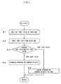
- the numerical control unit 10 inputs through the not-shown input means a set temperature value to be used for deciding whether or not the parameters of the velocity override are to be changed, and stores the set temperature value in the parameter storage means 12 (Step S1).
- the parameter changing means 11 in puts the temperature data of the servo-amplifier 5 from the temperature measuring device such as a temperature sensor mounted in the servo-amplifier 5 (Step S2), and compares it with the set temperature value stored at Step S1 (Step S3).
- Step S3 If this comparison of Step S3 reveals that the temperature of the servo-amplifier is higher than the set value, it is decided that the servo-amplifier is overheated, and the override of the command voltage to be fed to the servo-amplifier 5 is decreased. This decrease can be effected by reading either the override value according to the temperature of the servo-amplifier or the corrected value of the override value from the parameter storage means 12 and by changing the override value with the read value (Step S4).
- the override value can be changed by using not the value according to the temperature of the servo-amplifier but a predetermined constant value or a corrected value of the override value.
- Step S5 When the comparison of Step S3 reveals that the temperature of the servo-amplifier is lower than the set value, it is decided that the temperature of the servo-amplifier is normal, and the override of the command velocity to be fed to the servo-amplifier 5 is returned to 100 %. This return can be made in the parameter changing means 11 (Step S5).
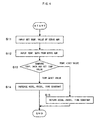
- the numerical control unit 10 inputs through the not-shown input means the set temperature value to be used for deciding whether or not the parameter of the acceleration/deceleration time constant is to be changed, and stores the set temperature in the parameter storage means 12 (Step S11).
- the parameter changing means 11 inputs the temperature data of the servo-amplifier 5 from the temperature measuring device such as the temperature sensor mounted in the servo-amplifier 5 (Step S12), and compares the temperature data with the set temperature value stored at Step S1 (Step S13).
- Step S13 When the comparison of Step S13 reveals that the temperature of the servo-amplifier is higher than the set value, it is decided that the servo-amplifier is overheated, and the acceleration/deceleration time constant of the command voltage to be fed to the servo-amplifier 5 is increased.
- This operation can be performed by reading either the acceleration/deceleration time constant according to the temperature of the servo-amplifier or the corrected value of the acceleration/deceleration time constant from the parameter storage means 12 and by changing the value of the acceleration/deceleration time constant with the read value (Step S14).
- the value of the acceleration/deceleration time constant can also be changed by using not the value according to the temperature of the servo-amplifier but either a predetermined constant value or the corrected value of the acceleration/deceleration time constant.
- Step S13 When the comparison of Step S13 reveals that the temperature of the servo-amplifier is lower than the set value, it is decided that the temperature of the servo-amplifier is normal, and the acceleration/deceleration time constant of the command velocity to be fed to the servo-amplifier 5 is returned to the initial value.
- This operation can be performed in the parameter changing means 11 (Step S15).
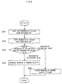
- the numerical control unit 10 inputs through the not-shown input means a set regenerative voltage value to be used for deciding whether or not the parameters of the velocity override are to be changed, and stores it in the parameter storage means 12 (Step S21).
- the parameter changing means 11 inputs the regenerative voltage data generated on the side of the electric motor in the servo-amplifier 5 and returned to the servo-amplifier 5 (Step S22), and compares it with the set regenerative voltage value stored at Step S21 (Step S23).
- Step S23 If this comparison of Step S23 reveals that the regenerative voltage to the servo-amplifier is higher than the set value, it is decided that the servo-amplifier is in an over-voltage state, and the override of the command voltage to be fed to the servo-amplifier 5 is decreased.
- This decrease can be effected by reading either the override value according to the regenerative voltage of the servo-amplifier or the corrected value of the override value from the parameter storage means 12 and by changing the override value with the read value (Step S24).
- the override value can be changed by using a predetermined constant override value or a corrected value.
- Step S23 When the comparison of Step S23 reveals that the regenerative voltage of the servo-amplifier is lower than the set value, it is decided that the voltage of the servo-amplifier is normal or that the command velocity can be fed as it is, and the override of the command velocity to be fed to the servo-amplifier 5 is returned to 100 %. This return can be effected in the parameter changing means 11 (Step S25).
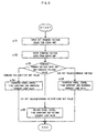
- the numerical control unit 10 inputs through the not-shown input means a set regenerative voltage value to be used for deciding whether or not the parameters of the acceleration/deceleration time constant are to be changed, and stores it in the parameter storage means 12 (Step S31).
- the parameter changing means 11 inputs the regenerative voltage data generated on the side of the electric motor in the servo-amplifier 5 and returned to the servo-amplifier 5 (Step S32), and compares it with the set regenerative voltage value stored at Step S31 (Step S33).
- Step S33 If this comparison of Step S33 reveals that the regenerative voltage to the servo-amplifier is higher than the set value, it is decided that the servo-amplifier is in an over-voltage state, and the acceleration decelaration time constant of the command velocity to be fed to the servo-amplifier 5 is increased.
- This increase can be effected by reading in the parameter changing means 11 either the acceleration/deceleration time constant according to the regenerative voltage or the corrected value of the acceleration/deceleration time constant from the parameter storage means 12 and by changing the acceleration/deceleration time constant with the read value (Step S34).
- the acceleration/deceleration time constant can be changed by using a predetermined constant acceleration/deceleration time constant or a corrected value.
- Step S33 When the comparison of Step S33 reveals that the regenerative voltage of the servo-amplifier is lower than the set value, it is decided that the voltage of the servo-amplifier is normal or that the command velocity can be fed as it is, and the acceleration/deceleration time constant of the command velocity to be fed to the servo-amplifier 5 is returned to the initial value. This return can be effected in the parameter changing means 11 (Step S35).
- the numerical control unit 10 inputs through the not-shown input means the set command voltage value to be used for deciding whether or not the parameters of the acceleration/deceleration time constant and the current loop gain are to be changed, and stores it in the parameter storage means 12 (Step S41).
- the parameter changing means 11 inputs the command voltage data from the servo-amplifier 5 (Step S42), and compares the command voltage data with the set command voltage value stored at Step S41 (Step S43).
- Step S43 When the comparison of Step S43 reveals that the command voltage to the servo-amplifier is lower than the set value, it is decided that, the servo-amplifier is in a low voltage state, and the acceleration/deceleration time constant and the current loop gain of the command velocity to be fed to the servo-amplifier 5 are increased.
- These operations can be performed in the parameter changing means 11 by reading either the value of the acceleration/deceleration time constant according to the input raw voltage or the corrected value of the acceleration/deceleration time constant, and either the value of current loop gain or the corrected value of the current loop gain from the parameter storage means 12, and by changing the acceleration/deceleration time constant and the current loop gain with the read values (Step S44).
- acceleration/deceleration time constant and the current loop gain can also be changed by using not the value according to the command voltage but either a predetermined constant value or a corrected value of the acceleration/deceleration time constant and either the value of the current loop gain or the corrected value of the current loop gain.
- Step S43 When the comparison of Step S43 reveals that the command voltage is higher than the set value, it is decided that the voltage of the servo-amplifier is in a high voltage state, and the acceleration/deceleration time constant of the command velocity and the current loop gain to be fed to the servo-amplifier 5 are decreased. This decrease can be effected in the parameter changing means 11 (Step S45).
- the aforementioned routine is exemplified by changing both the acceleration/deceleration time constant and the voltage loop gain. By changing one of these, however, the operations of the electric motor can also be stabilized.
- the numerical control unit 10 inputs through the not-shown input means first and second set values of the command voltage to be used for deciding whether or not the parameters of the acceleration/deceleration time constant and the current loop gain are to be changed, and stores them in the parameter storage means 12 and the like.
- the first and second set values are respectively set to values lower and higher than the command voltage in comparision with the normal state (Step S51).
- the parameter changing means 11 inputs the command voltage data fed to the servo-amplifier 5 (Step S52), and it is compared with the set command voltage value which is stored at Step S51 (Step S53).
- Step S53 When the comparison of Step S53 reveals that the command voltage to the servo-amplifier is lower than the first set value, it is decided that the servo-amplifier is in a low voltage state, and the acceleration/deceleration time constant of the command velocity and the current loop gain to be fed to the servo-amplifier 5 are increased.
- This increase can be effected in the parameter changing means 11 by reading the value or the corrected value of the acceleration/deceleration time constant according to the input voltage and the value or the corrected value of the current loop gain from the parameter storage means 12, and by changing the acceleration/deceleration time constant and the current loop gain with the read value (Step S54).
- acceleration/deceleration time constant and the current loop gain can also be changed by using not the value according to the command voltage but a predetermined constant value or the corrected value of the acceleration/deceleration time constant and the value or the corrected value of the current loop gain.
- Step S53 When the comparison of Step S53 reveals that the command voltage is higher than the second set value, it is decided that the voltage of the servo-amplifier is in a high voltage state, the acceleration/deceleration time constant of the command velocity and the current loop gain to be fed to the servo-amplifier 5 are decreased. This decrease can be effected in the parameter changing means 11 (Step S55).
- Step S53 when the comparison of Step S53 reveals that the command voltage is between the first set value and the second set value, it is decided that the voltage of the servo-amplifier is in the normal state, and the acceleration/deceleration time constant of the command velocity and the current loop gain to be fed to the servo-amplifier 5 are returned to the initial steady values. This return can be effected in the parameter changing means 11 (Step S56).
- the aforementioned routine is exemplified by changing both the acceleration/deceleration time constant and the voltage loop gain. By changing one of these, however, the operations of the electric motor can also be stabilized.
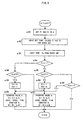
- FIG. 9 is a flow chart for explaining in more detail the operations to change at least one of the velocity override and the acceleration/deceleration time constant with the temperature of the servo-amplifier
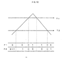
- FIG. 10 is an explanatory diagram for the flow chart.
- Step S61 flags F1 and F2 to be used for this routine are initially set to "0" (Step S61).
- the numerical control unit 10 inputs through the not-shown input means a first set value T1 and a second set value T2 of the temperature of the servo-amplifier to be used for deciding whether or not the parameters of the override value of the velocity command and the acceleration/deceleration time constant are to be changed, and stores them in the parameter storage means 12.
- the first and second set temperature values T1 and T2 are respectively set at values higher and lower than the temperature in comparison with the normal state (at Step S62).
- the parameter changing means 11 inputs a temperature Tp of the servo-amplifier 5 from the temperature measuring means such as a temperature sensor mounted in the servo-amplifier 5 (Step S 63).
- Step S64 it is decided whether or not the flag F1 is set at "1" (Step S64). Incidentally, this flag F1 and the flag F2 have been initially set to "0" when the power is ON (Step S61).
- the flag F1 is not at "1"
- the temperature Tp of the servo-amplifier is compared with the first set value T1 which is set as may cause the servo-amplifier to overheat.
- the flag F2 which has also been initially set to "0", as described above
- Step S65 the routine advances from Step S65 to Step S66, at which the flag F1 is set to "1" and the flag F2 is set to "0" to adjust an override value A and an acceleration/deceleration time constant B.
- this override value A is decreased by a set value ⁇ A.
- this acceleration/deceleration time constant B is increased by a set value ⁇ B (Step S67).
- these parameters i.e., the override value A and the acceleration/deceleration time constant B
- these parameters are held at the values which are either initially set at the operation starting time before the adjustment or set with the operation program.
- the value of the velocity command to be fed to the servo-amplifier is decreased when the override value A is decreased, and the current to flow through the motor at the acceleration/deceleration time of the motor is decreased when the acceleration/deceleration time constant B is increased.
- Step S67 the parameters of the override value and the acceleration/deceleration time constant are adjusted to lower the servo-amplifier temperature.
- the flag F1 is set at "1" so that the routine advances from Step S64 to Step S68, at which it is decided whether or not the servo-amplifier temperature Tp of Step S63 is lower than the second set value T2.
- the second set value T2 is set to a temperature lower than the first set value T1 (i.e., T1 > T2) and is a set value becoming a reference for switching the parameters from the state, in which the servo-amplifier temperature is adjusted in the decreasing direction, to the state in which the same is adjusted in the increasing direction.
- Step S68 When it is decided at Step S68 that the servo-amplifier temperature Tp is not equal to or lower than the second set value T2, the routine advances to Step S67, at which the parameters are adjusted in the direction to lower the servo-amplifier temperature, and is then ended.
- Step S63 At and after the subsequent routine, so long as the servo-amplifier temperature Tp of Step S63 is higher than the second set value T2, the operations of Steps S61 to S64, Step S68 and Step S67 are performed, and the parameters are sequentially changed in a direction to lower the servo-amplifier temperature at Step S67.
- Step S6A When the parameters are changed in the direction to lower the servo-amplifier temperature so that the servo-amplifier temperature Tp becomes lower than the second set value T2, the routine skips from Step S68 to Step S69, at which the flag F1 is set to "0" and the flag F2 is set to "1" so that the parameters are adjusted in the direction to increase the servo-amplifier temperature (Step S6A).
- This routine is ended by effecting at least one of the selected adjustments to increase the override value A by a set amount ⁇ A' and to decrease the acceleration/deceleration time constant B by a set amount ⁇ B'.
- Step S61 the routine advances to Step S65, at which it is decided whether or not the servo-amplifier temperature Tp is equal to or lower than the first set value T1. If this answer is YES, the routine advances to Step S6B, at which it is decided whether or not the flag F2 is at "1". Since the flag F2 is set at "1" at this time, the routine advances to Step S6A, at which the parameters are adjusted in the direction to increase the servo-amplifier temperature.
- Step S61 to S65, Step S6B and Step S6A are executed in every routines in the direction to increase the servo-amplifier temperature gradually.
- the servo-amplifier temperature Tp rises.
- the routine advances from Step S65 to Step S66, at which the flag F1 is set to "1" whereas the flag F2 is set to "0", and the parameters are adjusted in the direction to decrease the servo-amplifier temperature (Step S67).
- the flag F1 is set at "1"
- the operations of the Steps S61 to S64, Step S68 and Step S67 are executed in every routines to adjust the parameters gradually in the direction to decrease the servo-amplifier temperature.
- the servo-amplifier temperature lowers.
- Step S61 to S65, Step S6B and Step S6A are executed to effect adjustments in the direction to increase the motor temperature repeatedly thereby to change the individual parameters in the direction to increase the servo-amplifier temperature gradually.
- the parameters are sequentially adjusted in the direction to decrease the servo-amplifier temperature (either by decreasing the override value A sequentially by ⁇ A or by increasing the acceleration/deceleration time constant B sequentially by ⁇ B).
- the servo-amplifier temperature Tp becomes equal to or lower than the second set value T2
- the parameters are sequentially adjusted in the direction to increase the servo-amplifier temperature, on the contrary.
- the parameter adjustments are effected to hold the servo-amplifier temperature Tp between the first and second set values T1 and T2 so that the operational instability of the electric motor as might otherwise be caused by the rise in the servo-amplifier temperature can be prevented.
- the aforementioned operations can be performed either for one electric motor having the servo-amplifier of the highest temperature-change or for all the servo-amplifiers.
- Step S64 it is decided whether or not the temperature Tp of all the servo-amplifiers is equal to or less than the first set value T1 which is set for the individual servo-amplifiers.
- the routine advances to Step S6B.
- the routine advances to Step S66.
- Step S68 decides that the temperature Tp of all the servo-amplifiers is equal to or lower than the second set value T2 which is set for each of the servo-amplifiers
- the routine advances to Step S69.
- the routine advances to Step S67.
- the parameters i.e., the override value A and the acceleration/deceleration time constant B
- the parameters are left at their initially set values till the servo-amplifier temperature Tp exceeds the first set value T1.
- the parameters can be adjusted.
- Step S66 and Step S69 are to set the flag F1 to "1" or "0".
- the routine advances to Step S6A.
- Step S6A When the servo-amplifier temperature Tp is equal to or lower than the first set value T1, the routine advances to Step S6A, at which the parameters are adjusted in the direction to increase the motor temperature.
- Step S66 When the servo-amplifier temperature Tp exceeds the first set value T1, the routine advances to Step S66, at which the flag F1 is set to "1", and the parameters are adjusted in the direction to decrease the servo-amplifier temperature.
- the parameters are adjusted in the direction to decrease the servo-amplifier temperature in every routines till the servo-amplifier temperature Tp becomes equal to or lower than the second set value T2 (Steps S61 to S64, Step S68 and Step S67).
- the flag F1 is set to "0", and the parameters are adjusted in the direction to increase the servo-amplifier temperature till the servo-amplifier temperature Tp reaches the first set value T1. From now on, these operations are repeated.
- the parameters for adjusting the temperature of the servo-amplifier are exemplified by the override value and the acceleration/deceleration time constant.
- the controllable factors relating to the temperature rise of the servo-amplifier such as the maximum velocity or the operation stopping time can be likewise applied.
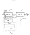
- FIG. 11 is a schematic diagram for explaining a construction for compensating the current offset in accordance with the temperature of the servo-amplifier.
- the servo-amplifier 5 drives the electric motor M on the basis of a command coming from a current loop 14 which belongs to the not-shown numerical control unit.
- the feedback data include not only the feedback current of the motor but also the offset data of an electronic device such as an A/D converter or an insulating amplifier. These offset data cause irregular rotations of the motor.
- the electric motor controller is equipped in the numerical control unit with offset compensation means 13 for compensating the offset current.
- This offset compensation means 13 includes temperature-offset data storage means 12' for storing the temperature-offset data, and offset calculation means 11' for determining an offset value on the basis of the offset data obtained from the temperature-offset data storage means 12'.
- the offset compensation means 13 performs the offset compensation with the temperature data coming from the servo-amplifier 5.
- FIG. 12 is a flow chart for explaining the operations of the offset compensation.
- the current offset data are obtained against the temperature of the servo-amplifier, as illustrated in FIG. 13. This relation illustrates the determination of the current offset data from the temperature of the servo-amplifier. Therefore, the characteristics between the servo-amplifier temperature and the current offset data are beforehand measured and stored in the temperature-offset data storage means 12'. Incidentally, these characteristics may be stored in an arbitrary storage format such as a data table or a calculation formula (Step S71).
- the temperature data are determined from the servo-amplifier 5 and are stored in the temperature-offset data storage means 12' (Step S72), and the offset data corresponding to the temperature data are read (Step S73).
- the offset compensation means 13 compensates the current offset by calculating the offset value using the read offset data and by eliminating the calculated value from the feedback current of the current loop (Step S74).
- the offset data can be determined on real time without reducing the motor feedback current to 0, so that the offset compensation of the feedback current can be effected without any time delay.
- the data of the servo-amplifier are monitored, and a malfunction is decided when the monitored value exceeds a preset value, so that a warning can be issued by feeding an abnormal signal or the like to the numerical control unit.
- the velocity override, the acceleration/deceleration time constant, the current loop gain and the current offset can be adjusted by measuring the temperature, the command voltage, the regenerative voltage and the like of the servo-amplifier.
Landscapes
- Engineering & Computer Science (AREA)
- Human Computer Interaction (AREA)
- Manufacturing & Machinery (AREA)
- Physics & Mathematics (AREA)
- General Physics & Mathematics (AREA)
- Automation & Control Theory (AREA)
- Control Of Electric Motors In General (AREA)
- Control Of Ac Motors In General (AREA)
- Numerical Control (AREA)
Claims (9)
- Regelungsvorrichtung (10) zur Regelung eines Elektromotors (M) durch Ausgeben eines Befehla an einen Servoverstärker (5) zum Treiben des Elektromotors (M), wobei die Regelungsvorrichtung (10) ein Parameteränderungsmittel (11) umfasst, das betriebsfähig ist, einen Regelungsparameter zur Regelung des Elektromotors (M) auf der Grundlage der Temperatur des Servo-Verstärkers (5) derart zu ändern, dass die Regelungsvorrichtung (10) einen Eingabebefehl auf der Grundlage des geänderten Regelungsparameters an den Servoverstärker (5) ausgeben wird,
dadurch gekennzeichnet, dass das Parameteränderungsmittel (11) betriebsfähig ist, den Motor-Regelungsparameter auf der Grundlage irgendeiner oder mehrerer der Größen Temperatur, Befehlsspannung und Rückkopplungsspannung des Servo-Verstärkers (5) zu ändern, wobei der Motor-Regelungsparameter, der geändert wird, irgendeine oder mehrere der Größen Geschwindigkeitsübersteuerungs-Beschränkungsmaß zum Beschränken einer befohlenen Motor-Geschwindigkeit, Beschleunigungs/Verzögerungs-Zeitkonstante, Stromregelungsschleifen-Übertragungsfaktor und Versatzwert eines Motor-Rückkopplungsstroms umfasst. - Regelungsvorrichtung (10) nach Anspruch 1, wobei das Parameteränderungsmittel (11) betriebsfähig ist, die Motor-Regelungsparameter-Geschwindigkeitsübersteuerung auf der Grundlage der Temperatur des Servo-Verstärkers (5) zu ändern.
- Regelungsvorrichtung (10) nach Anspruch 1, wobei das Parameteränderungsmittel (11) betriebsfähig ist, die Motor-Regelungsparameter-Beschleunigungs/Verzögerungs-Zeitkonstante auf der Grundlage der Temperatur des Servo-Verstärkers (5) zu ändern.
- Regelungsvorrichtung (10) nach Anspruch 1, wobei das Parameteränderungsmittel (11) betriebsfähig ist, das Motor-Regelungsparameter-Geschwindigkeitsübersteuerungsmaß auf der Grundlage der Rückkopplungsspannung des Servo-Verstärkers (5) zu ändern.
- Regelungsvorrichtung (10) nach Anspruch 1, wobei das Parameteränderungsmittel (11) betriebsfähig ist, die Motor-Regelungsparameter-Beschleunigungs/Verzögerungs-Zeitkonstante auf der Grundlage der Rückkopplungsspannung des Servo-Verstärkers (5) zu ändern.
- Regelungsvorrichtung (10) nach Anspruch 1, wobei das Parameteränderungsmittel (11) betriebsfähig ist, die Motor-Regelungsparameter-Beschleunigungs/Verzögerungs-Zeitkonstante auf der Grundlage der Befehlsspannung des Servo-Verstärkers (5) zu ändern.
- Regelungsvorrichtung (10) nach Anspruch 1, wobei das Parameteränderungsmittel (11) betriebsfähig ist, die Motor-Regelungsparameter-Beschleunigungs/Verzögerungs-Zeitkonstante und den Stromregelungsschleifen-Übertragungsfaktor auf der Grundlage der Befehlsspannung des Servo-Verstärkers (5) zu ändern.
- Regelungsvorrichtung (10) nach Anspruch 1, wobei das Parameteränderungsmittel (11) betriebsfähig ist, das Motor-Regelungsparameter-Geschwindigkeitsübersteuerungsmaß und die Beschleunigungs/Verzögerungs-Zeitkonstante auf der Grundlage der Temperatur des Servo-Verstärkers (5) zu ändern.
- Regelungsvorrichtung (10) nach Anspruch 1, wobei das Parameteränderungsmittel (11) betriebsfähig ist, den Motor-Regelungsparameter-Versatzwert des Motor-Rückkopplungsstroms auf der Grundlage der Temperatur des Servo-Verstärkers (5) zu ändern.
Applications Claiming Priority (2)
| Application Number | Priority Date | Filing Date | Title |
|---|---|---|---|
| JP36684197 | 1997-12-26 | ||
| JP36684197A JP3252114B2 (ja) | 1997-12-26 | 1997-12-26 | 電動モータの制御装置 |
Publications (2)
| Publication Number | Publication Date |
|---|---|
| EP0926577A1 EP0926577A1 (de) | 1999-06-30 |
| EP0926577B1 true EP0926577B1 (de) | 2004-03-17 |
Family
ID=18487816
Family Applications (1)
| Application Number | Title | Priority Date | Filing Date |
|---|---|---|---|
| EP19980310778 Expired - Lifetime EP0926577B1 (de) | 1997-12-26 | 1998-12-29 | Steuerung für elektrischen Motor |
Country Status (3)
| Country | Link |
|---|---|
| EP (1) | EP0926577B1 (de) |
| JP (1) | JP3252114B2 (de) |
| DE (1) | DE69822425T2 (de) |
Families Citing this family (10)
| Publication number | Priority date | Publication date | Assignee | Title |
|---|---|---|---|---|
| JP3710673B2 (ja) * | 2000-03-17 | 2005-10-26 | 三菱電機株式会社 | 車載用電動機制御装置 |
| JP4490671B2 (ja) * | 2003-11-11 | 2010-06-30 | 日立オートモティブシステムズ株式会社 | 位置制御装置 |
| FR2900360B1 (fr) * | 2006-04-28 | 2008-06-20 | Staubli Faverges Sca | Procede et dispositif de reglage de parametres de fonctionnement d'un robot, programme et support d'enregistrement pour ce procede |
| JP5149410B2 (ja) | 2011-02-10 | 2013-02-20 | ファナック株式会社 | 交流電源の電源特性に応じてモータの出力を制限するモータ駆動制御装置 |
| US9939804B2 (en) | 2013-12-13 | 2018-04-10 | Mitsubishi Electric Corporation | Numerical control device and numerical control method |
| JP6848845B2 (ja) * | 2017-12-15 | 2021-03-24 | オムロン株式会社 | サーボモータの負荷状態診断装置及び負荷状態診断方法 |
| JP7343319B2 (ja) * | 2019-07-19 | 2023-09-12 | ファナック株式会社 | サーボ制御装置 |
| CN114089707B (zh) * | 2021-11-18 | 2023-09-22 | 佛山冠湾智能科技有限公司 | 一种伺服驱动系统报警装置及报警方法 |
| JP7744862B2 (ja) | 2022-03-24 | 2025-09-26 | シチズン時計株式会社 | 工作機械及び工作機械の制御装置 |
| DE112023006082T5 (de) * | 2023-09-04 | 2026-06-25 | Mitsubishi Electric Corporation | Mehrachsen-Steuergerät, Mehrachsen-Steuersystem, Tuning-Verfahren und Programm |
Family Cites Families (2)
| Publication number | Priority date | Publication date | Assignee | Title |
|---|---|---|---|---|
| US4779031A (en) * | 1985-12-30 | 1988-10-18 | Intellico, Inc. | Motor system |
| JP3107711U (ja) | 2004-09-13 | 2005-02-03 | 和夫 鮎川 | トレーラ用補助架台 |
-
1997
- 1997-12-26 JP JP36684197A patent/JP3252114B2/ja not_active Expired - Fee Related
-
1998
- 1998-12-29 EP EP19980310778 patent/EP0926577B1/de not_active Expired - Lifetime
- 1998-12-29 DE DE69822425T patent/DE69822425T2/de not_active Expired - Lifetime
Also Published As
| Publication number | Publication date |
|---|---|
| DE69822425D1 (de) | 2004-04-22 |
| JP3252114B2 (ja) | 2002-01-28 |
| DE69822425T2 (de) | 2004-07-29 |
| EP0926577A1 (de) | 1999-06-30 |
| JPH11194807A (ja) | 1999-07-21 |
Similar Documents
| Publication | Publication Date | Title |
|---|---|---|
| JP3902710B2 (ja) | 数値制御による工作機械の制御方法及び装置 | |
| US4556830A (en) | Speed controller for mill drives and the like | |
| EP0468806B1 (de) | Temperatursteuerungssystem für Motoren und Leistungsbestandteile eines Material-Handhabungsfahrzeuges | |
| US4540923A (en) | Adaptive servomotor controller | |
| EP0926577A1 (de) | Steuerung für elektrischen Motor | |
| US11353830B2 (en) | Servo control method | |
| US6796924B2 (en) | Engine revolution controlling apparatus | |
| US5874813A (en) | Control method, especially for load balancing of a plurality of electromotor drives | |
| JP3370040B2 (ja) | 速度制御装置 | |
| US20050168186A1 (en) | Servomotor control device for robot and robot having the device | |
| JP2010142049A (ja) | 多軸モータドライブシステムとその共通コンバータの過負荷保護方法及び装置 | |
| CN101496275A (zh) | 驱动装置和方法 | |
| US5050709A (en) | Elevator control apparatus | |
| JP2008225652A (ja) | 数値制御装置 | |
| JPH06289917A (ja) | 推定外乱負荷トルクによるサーボモータ制御方法 | |
| JP2007336669A (ja) | 電源系統安定化方法及びその方法を用いた電源系統安定化システム | |
| JPH1080055A (ja) | モータのオーバヒート抑制制御方法 | |
| JP3175417B2 (ja) | Acサ−ボモ−タの過負荷保護装置 | |
| KR100805242B1 (ko) | 서보모터의 제어시스템 및 그 제어방법 | |
| JP3810461B2 (ja) | サーボアンプの並列運転方法 | |
| JPH11155294A (ja) | モータ駆動装置 | |
| JPH06282302A (ja) | Dcサーボモータの制御方法 | |
| JP2652977B2 (ja) | 数値制御装置 | |
| JPH08126204A (ja) | 系統安定化装置 | |
| JPH0564476A (ja) | 電動機の速度制御装置 |
Legal Events
| Date | Code | Title | Description |
|---|---|---|---|
| PUAI | Public reference made under article 153(3) epc to a published international application that has entered the european phase |
Free format text: ORIGINAL CODE: 0009012 |
|
| AK | Designated contracting states |
Kind code of ref document: A1 Designated state(s): DE |
|
| AX | Request for extension of the european patent |
Free format text: AL;LT;LV;MK;RO;SI |
|
| 17P | Request for examination filed |
Effective date: 19991213 |
|
| AKX | Designation fees paid |
Free format text: DE |
|
| 17Q | First examination report despatched |
Effective date: 20020802 |
|
| GRAP | Despatch of communication of intention to grant a patent |
Free format text: ORIGINAL CODE: EPIDOSNIGR1 |
|
| GRAS | Grant fee paid |
Free format text: ORIGINAL CODE: EPIDOSNIGR3 |
|
| GRAA | (expected) grant |
Free format text: ORIGINAL CODE: 0009210 |
|
| AK | Designated contracting states |
Kind code of ref document: B1 Designated state(s): DE |
|
| REF | Corresponds to: |
Ref document number: 69822425 Country of ref document: DE Date of ref document: 20040422 Kind code of ref document: P |
|
| RAP2 | Party data changed (patent owner data changed or rights of a patent transferred) |
Owner name: FANUC LTD |
|
| PLBE | No opposition filed within time limit |
Free format text: ORIGINAL CODE: 0009261 |
|
| STAA | Information on the status of an ep patent application or granted ep patent |
Free format text: STATUS: NO OPPOSITION FILED WITHIN TIME LIMIT |
|
| 26N | No opposition filed |
Effective date: 20041220 |
|
| REG | Reference to a national code |
Ref country code: DE Ref legal event code: R082 Ref document number: 69822425 Country of ref document: DE Representative=s name: HASELTINE LAKE LLP, DE |
|
| PGFP | Annual fee paid to national office [announced via postgrant information from national office to epo] |
Ref country code: DE Payment date: 20151222 Year of fee payment: 18 |
|
| REG | Reference to a national code |
Ref country code: DE Ref legal event code: R119 Ref document number: 69822425 Country of ref document: DE |
|
| PG25 | Lapsed in a contracting state [announced via postgrant information from national office to epo] |
Ref country code: DE Free format text: LAPSE BECAUSE OF NON-PAYMENT OF DUE FEES Effective date: 20170701 |