EP0926763A1 - Organe de contact à pression avec boítier - Google Patents
Organe de contact à pression avec boítier Download PDFInfo
- Publication number
- EP0926763A1 EP0926763A1 EP98309568A EP98309568A EP0926763A1 EP 0926763 A1 EP0926763 A1 EP 0926763A1 EP 98309568 A EP98309568 A EP 98309568A EP 98309568 A EP98309568 A EP 98309568A EP 0926763 A1 EP0926763 A1 EP 0926763A1
- Authority
- EP
- European Patent Office
- Prior art keywords
- fitting
- pressure contact
- terminal fitting
- terminal
- housing
- Prior art date
- Legal status (The legal status is an assumption and is not a legal conclusion. Google has not performed a legal analysis and makes no representation as to the accuracy of the status listed.)
- Granted
Links
- 230000013011 mating Effects 0.000 claims description 2
- 230000014759 maintenance of location Effects 0.000 claims 2
- 238000005452 bending Methods 0.000 abstract description 6
- 230000037431 insertion Effects 0.000 description 2
- 238000003780 insertion Methods 0.000 description 2
- 230000000694 effects Effects 0.000 description 1
- 238000009413 insulation Methods 0.000 description 1
- 230000001105 regulatory effect Effects 0.000 description 1
- 230000000717 retained effect Effects 0.000 description 1
- 229920003002 synthetic resin Polymers 0.000 description 1
- 239000000057 synthetic resin Substances 0.000 description 1
Images


Classifications
-
- H—ELECTRICITY
- H01—ELECTRIC ELEMENTS
- H01R—ELECTRICALLY-CONDUCTIVE CONNECTIONS; STRUCTURAL ASSOCIATIONS OF A PLURALITY OF MUTUALLY-INSULATED ELECTRICAL CONNECTING ELEMENTS; COUPLING DEVICES; CURRENT COLLECTORS
- H01R13/00—Details of coupling devices of the kinds covered by groups H01R12/70 or H01R24/00 - H01R33/00
- H01R13/40—Securing contact members in or to a base or case; Insulating of contact members
- H01R13/42—Securing in a demountable manner
- H01R13/428—Securing in a demountable manner by resilient locking means on the contact members; by locking means on resilient contact members
- H01R13/432—Securing in a demountable manner by resilient locking means on the contact members; by locking means on resilient contact members by stamped-out resilient tongue snapping behind shoulder in base or case
-
- H—ELECTRICITY
- H01—ELECTRIC ELEMENTS
- H01R—ELECTRICALLY-CONDUCTIVE CONNECTIONS; STRUCTURAL ASSOCIATIONS OF A PLURALITY OF MUTUALLY-INSULATED ELECTRICAL CONNECTING ELEMENTS; COUPLING DEVICES; CURRENT COLLECTORS
- H01R4/00—Electrically-conductive connections between two or more conductive members in direct contact, i.e. touching one another; Means for effecting or maintaining such contact; Electrically-conductive connections having two or more spaced connecting locations for conductors and using contact members penetrating insulation
- H01R4/24—Connections using contact members penetrating or cutting insulation or cable strands
- H01R4/2416—Connections using contact members penetrating or cutting insulation or cable strands the contact members having insulation-cutting edges, e.g. of tuning fork type
- H01R4/2445—Connections using contact members penetrating or cutting insulation or cable strands the contact members having insulation-cutting edges, e.g. of tuning fork type the contact members having additional means acting on the insulation or the wire, e.g. additional insulation penetrating means, strain relief means or wire cutting knives
- H01R4/245—Connections using contact members penetrating or cutting insulation or cable strands the contact members having insulation-cutting edges, e.g. of tuning fork type the contact members having additional means acting on the insulation or the wire, e.g. additional insulation penetrating means, strain relief means or wire cutting knives the additional means having two or more slotted flat portions
Definitions
- the present invention relates to a pressure contact electrical connector.
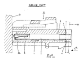
- Figure 9 shows a conventional pressure contact connector 6 comprising a connector housing 1, and a female pressure contact terminal fitting 2 housed in a terminal housing chamber 3 formed within the connector housing 1.
- the terminal fitting 2 has a long and narrow box-shape, a resilient contact member 5 being formed on the anterior end thereof, the contact member 5 fitting together with a corresponding terminal fitting (not shown).
- a pressure contact blade 4 is provided on the posterior end of the pressure contact terminal fitting 2, an insulated electric wire W fitting thereto.
- the electric wire W is attached to the pressure contact terminal fitting 2 by an automated machine. That is, the insulated wire W is pressed by a pressing means (not shown) of an automated machine onto the pressure contact blade 4, the blade 4 and wire W accordingly becoming electrically connected.
- a pressing force from the automated machine acts upon the posterior end face of the pressure contact terminal fitting 2 in the direction of arrow A, this force passing through the anterior face wall 3A of the terminal housing chamber 3 and being received and stopped by the receiving face 9.
- the pressure contact terminal fitting 2 is clamped between its anterior and posterior ends.
- the pressure contact terminal fitting 2 has a long and narrow shape in the anterior-posterior direction. Consequently, in the case where the pressing force from the automated machine is high, there is the possibility that the pressure contact terminal fitting 2 could change shape and bend inside the chamber 3.
- the present invention has been developed after taking the above problem into consideration, and aims to present a pressure contact terminal fitting which does not bend when the wire is pushed into the blade 4.
- an electrical connector comprising a housing, a chamber in the housing, and an elongate pressure contact terminal fitting insertable within said chamber along an axis thereof, one end of said fitting having a slot extending in the direction of said axis, said slot defining a pressure contact blade for connection to an electric wire, and the other end of said fitting comprising a terminal for connection to a mating terminal fitting, wherein a mid-portion of said fitting has outwardly extending abutments on opposite sides thereof, said abutments being engageable with corresponding steps in the wall of said chamber, and resisting end loads applied to said one end along said axis.
- the abutments preferably lie in a common plane perpendicular to said axis, and comprise an outward protrusion or a step of said terminal.
- the terminal may include a retaining lance engageable with one side of an inner projection of said chamber, the other side of said projection being engageable by one of said abutments.
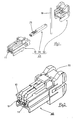
- Figure 1 is a diagonal view of a pressure contact connector according to the invention prior to being fitted together.
- Figure 2 is a diagonal view of the pressure contact connector after being fitted together.
- Figure 3 is a plan view of the pressure contact terminal fitting.
- Figure 4 is a side view of the pressure contact terminal fitting.
- Figure 5 is a front view of the pressure contact terminal fitting.
- Figure 6 is a side cross-sectional view of the pressure contact terminal fitting.
- Figure 7 is a side cross-sectional view of the connector housing.
- Figure 8 is a side cross-sectional view of the connector housing after the pressure contact connector has been attached thereto.
- Figure 9 is a side cross-sectional view of a prior art pressure contact connector.
- a pressure contact connector 40 has a connector housing 10, a female pressure contact terminal fitting 20 housed within the connector housing 10, and a cover 30 which covers the posterior portion of the connector housing 10.
- the anterior face of the pressure contact connector 40 is that face which fits together with a corresponding connector (not shown).
- the pressure contact terminal fitting 20 has a long and narrow angular tubular shape in an anterior-posterior direction.
- a resilient contact member 22 is formed on the anterior end portion of the pressure contact terminal fitting 20 by bending inwards a protruding portion of an anterior edge of a lower face 21.
- a tab of a male terminal fitting (not shown) is held resiliently between the resilient contact member 22 and an anterior upper face 23A, thereby bringing the male and female terminal fittings into an electrically connected state.
- a posterior upper face 23B and the lower face 21 are opened out on their left and right posterior ends to form a cut-away pressure contact member 24.
- This pressure contact member 24 corresponds to an electric wire receiving member 15 (to be explained later) of the connector housing 10.
- the insulated electric wire W is joined to the pressure contact member 24 by pushing in a posterior direction, cutting through the insulation thereof and bringing the core wire into contact with the pressure contact member 24.
- this lance 25 is engaged by a stopping face 14A (to be described later), and maintains the terminal fitting 20 in a retained state.
- the posterior upper face 23B rises to a specified height higher than the anterior upper face 23A, the boundary between the two plates constituting a step.
- the anterior edge portion of this step comprises a first protruding member 26.
- the height of the step between the first protruding member 26 and the anterior upper face 23A corresponds to the protruding height of a stopping protrusion 14 of the terminal housing chambers 11.
- the first protruding member 26 is formed by folding the end face of the posterior upper face 23B into a double layer.
- two slits are cut into the lower face 21 in the width-wise direction of the pressure contact terminal fitting 20, one slit being located close to the first protruding member 26 and the second slit being located somewhat posterior thereto. The portion between these is pushed out in a downwards direction from the lower face 21 to form a bridge-shaped protrusion 31, the anterior end of the bridge-shaped protrusion 31 comprising a second protruding member 29.
- the connector housing 10 is moulded from synthetic resin and, typically has a plurality of terminal housing chambers 11 are formed in a parallel manner on the right and left therein, the anterior and posterior faces of these terminal housing chambers 11 being open, and each terminal housing chamber 11 housing a pressure contact terminal fitting 20.
- the anterior openings of the chambers 11 form tab insertion holes 12 into which tabs of a corresponding male terminal fitting (not shown) are inserted, and the posterior openings of the chambers 11 form insertion holes 13 into which the terminal fittings 20 are inserted.
- the stopping protrusion 14 protrudes from the central portion of the upper face of each chamber 11.
- the anterior and posterior faces of the stopping protrusion 14 are approximately perpendicular relative to the upper wall face of the chambers 11, the anterior face thereof comprising the stopping face 14A.
- the lance 25 of the terminal fitting 20 is engaged by this stopping face 14A, thereby retaining the terminal fitting 20 inside the chamber 11.
- the posterior face of the stopping protrusion 14 comprises a first receiving member 18, this being capable of receiving and resisting the pushing force of the terminal fitting 20 by making contact with the first protruding member 26.
- a portion of the lower face of each chamber 11 forms a step-shaped portion, this portion being directly beneath the first receiving member 18.
- This step-shaped portion is formed by making the height of the lower face anterior to it higher than the height of the part of the lower face posterior to it.
- the step formed at the junction of these two differing heights constitutes a second receiving member 16.
- This second receiving member 16 is capable of receiving and resisting the pushing force of the terminal fitting 20 by making contact with the second protruding member 29.
- each chamber 11 The distance between the receiving members 18 and 16 and an anterior end face 11A of each chamber 11 is slightly greater than the distance between the protruding members 26 and 29 and the anterior end face 11A. Consequently, when the protruding members 26 and 29 are in a state in which they make contact with the receiving members 18 and 16, the anterior end face of the terminal fitting 20 and the anterior end face 11A of the chamber 11 do not make contact.
- Portions of the upper and lower face of the posterior end of the connector housing 10 are cut-away in a schematic U-shape to form the electric wire receiving member 15.
- the electric wire W is held firmly by pressure contact inside this electric wire receiving member 15, and the insulated portion of the electric wire W is slit so that it is in electrical contact with the terminal fitting 20.
- the terminal fitting 20 is inserted into the chamber 11 until it reaches the correct position (see Figure 8).
- the two protruding members 26 and 29 formed on the upper and lower faces of the terminal fitting 20 respectively make contact with the receiving members 18 and 16 in the chamber 11, thereby regulating the sliding of the pressure contact terminal fitting 20 in the anterior direction.
- the lance 25 and the stopping face 14A mutually face one another at the anterior side of the stopping protrusion 14, thereby retaining the pressure contact terminal fitting 20.
- a pushing jig (not shown) is used to push the electric wire W in an anterior direction, the pressure contact member 24 cutting into the electric wire W, the core wire being brought into contact with the pressure contact member 24, and thereby achieving an electrically connected state. While this operation is being performed, the pushing force exerted on the pressure contact terminal fitting 20 by the pushing jig brings the protruding members 26 and 29 and the receiving members 18 and 16 into contact, thereby resisting movement of the terminal fitting 20 inside the connector housing 10, the terminal fitting 20 being clamped between the pressure contact member 24 and the receiving members 18 and 16.
- the pushing force is received by the receiving members 18 and 16, these being located on the central portion of the pressure contact terminal fitting 20 in a length-wise direction.
- the length of the terminal fitting 20 which it is clamped is shorter compared to the case where the pushing force is received at the anterior end of the terminal fitting 20, and rigidity is thereby increased.
- the male terminal contact area is also relieved of pushing loads.
- the protruding members 26 and 29 and receiving members 18 and 16 are located along the direction in which the wire W extends, and are formed on the upper and lower faces of the terminal fitting 20.
- the lance 25 is provided on the side on which the first protruding member 26 is provided.
- the pressure contact connector 40 can be made smaller compared to a case in which a lance 25 is provided on a face not facing a receiving member (in the present embodiment, either the left or right face of the pressure contact terminal fitting 20).
Landscapes
- Connector Housings Or Holding Contact Members (AREA)
- Connections By Means Of Piercing Elements, Nuts, Or Screws (AREA)
Applications Claiming Priority (2)
| Application Number | Priority Date | Filing Date | Title |
|---|---|---|---|
| JP35991797 | 1997-12-26 | ||
| JP35991797A JP3282717B2 (ja) | 1997-12-26 | 1997-12-26 | 圧接コネクタ |
Publications (2)
| Publication Number | Publication Date |
|---|---|
| EP0926763A1 true EP0926763A1 (fr) | 1999-06-30 |
| EP0926763B1 EP0926763B1 (fr) | 2002-10-23 |
Family
ID=18466968
Family Applications (1)
| Application Number | Title | Priority Date | Filing Date |
|---|---|---|---|
| EP98309568A Expired - Lifetime EP0926763B1 (fr) | 1997-12-26 | 1998-11-23 | Organe de contact à pression avec boítier |
Country Status (5)
| Country | Link |
|---|---|
| US (1) | US6267616B1 (fr) |
| EP (1) | EP0926763B1 (fr) |
| JP (1) | JP3282717B2 (fr) |
| CN (1) | CN1221232A (fr) |
| DE (1) | DE69808878T2 (fr) |
Families Citing this family (9)
| Publication number | Priority date | Publication date | Assignee | Title |
|---|---|---|---|---|
| JP2002197943A (ja) * | 2000-12-25 | 2002-07-12 | Auto Network Gijutsu Kenkyusho:Kk | 自動車用電装部品のスイッチ構造 |
| DE10349486A1 (de) | 2002-10-25 | 2004-05-13 | Yazaki Corporation | Anschlussklemme und Steckverbindung |
| CN1319212C (zh) * | 2005-03-19 | 2007-05-30 | 齐俊曌 | 电线接续连接件 |
| CN100395919C (zh) * | 2006-08-17 | 2008-06-18 | 齐俊曌 | 改进的导线连接件 |
| KR101482793B1 (ko) * | 2008-06-16 | 2015-01-14 | 타이코에이엠피(유) | 커넥터 |
| DE102010029192B4 (de) * | 2010-05-20 | 2012-04-05 | Tyco Electronics Amp Gmbh | Steckverbinder und Steckmodulsystem |
| DE102012218234B4 (de) * | 2012-10-05 | 2025-11-13 | Robert Bosch Gmbh | Verrastbarer Kontakt mit von Seitenwand übergriffener Primärverriegelungslanze |
| CN103545634A (zh) * | 2013-11-04 | 2014-01-29 | 昆山美连德电子科技有限公司 | 一种线束端子 |
| TWI721615B (zh) * | 2019-10-24 | 2021-03-11 | 大陸商東莞訊滔電子有限公司 | 電連接器 |
Citations (6)
| Publication number | Priority date | Publication date | Assignee | Title |
|---|---|---|---|---|
| US3992072A (en) * | 1976-02-23 | 1976-11-16 | International Telephone And Telegraph Corporation | Electrical connector |
| GB1497274A (en) * | 1975-04-22 | 1978-01-05 | Pressac Ltd | Electric connectors or couplings |
| US4159158A (en) * | 1977-05-06 | 1979-06-26 | Amp Incorporated | Displation connector having improved terminal supporting means |
| EP0079599A1 (fr) * | 1981-11-13 | 1983-05-25 | Adc Telecommunications, Inc. | Module connecteur électrique |
| EP0321285A1 (fr) * | 1987-12-17 | 1989-06-21 | The Whitaker Corporation | Borne bidirectionnelle, pour contacts électriques, à déplacement de l'isolation |
| DE19628116C1 (de) * | 1996-07-12 | 1997-10-16 | Weidmueller Interface | Ein- oder mehrpoliger Steckverbinder für Einzelleiter |
Family Cites Families (18)
| Publication number | Priority date | Publication date | Assignee | Title |
|---|---|---|---|---|
| US2979689A (en) * | 1959-01-13 | 1961-04-11 | Jackson Anton | Element for detachably coupling electrical contacts with a connector body |
| US3566342A (en) | 1968-09-09 | 1971-02-23 | Bunker Ramo | Miniature connector |
| US3853388A (en) * | 1972-10-17 | 1974-12-10 | Prod Inc Van | Cluster assembly and connector clip therefor |
| GB1463751A (en) | 1974-05-03 | 1977-02-09 | Amp Inc | Electrical tab receptacle |
| FR2402949A1 (fr) * | 1977-09-09 | 1979-04-06 | Amp France | Connecteur electrique comportant un contact femelle loge dans un boitier isolant d'une seule piece |
| JPS60240072A (ja) | 1984-05-15 | 1985-11-28 | 日本航空電子工業株式会社 | 電気コネクタ及びその製造方法 |
| JPS62198063A (ja) | 1986-02-26 | 1987-09-01 | 矢崎総業株式会社 | フラツトケ−ブル圧接コネクタ |
| US4701004A (en) * | 1986-12-22 | 1987-10-20 | Amp Incorporated | Retention clip for electrical contacts |
| US4781628A (en) | 1987-10-22 | 1988-11-01 | General Motors Corporation | Female electrical terminal |
| US4960390A (en) | 1990-01-29 | 1990-10-02 | Amp Incorporated | Strain relief |
| JPH0749736Y2 (ja) * | 1990-03-22 | 1995-11-13 | 矢崎総業株式会社 | 保護スリーブ付雌端子金具 |
| JP3260193B2 (ja) | 1993-01-12 | 2002-02-25 | 三和電気工業株式会社 | 多段コネクタ |
| JP3216757B2 (ja) * | 1994-06-27 | 2001-10-09 | 矢崎総業株式会社 | 端 子 |
| US5489223A (en) * | 1994-10-17 | 1996-02-06 | Molex Incorporated | Electrical connector with terminal locking means |
| US5624273A (en) * | 1995-04-21 | 1997-04-29 | The Whitaker Corporation | Insulation displacement contact with strain relief |
| FR2741204A1 (fr) | 1995-11-14 | 1997-05-16 | Amp France | Assemblage de connecteur electrique |
| JPH10247545A (ja) | 1997-03-03 | 1998-09-14 | Sumitomo Wiring Syst Ltd | 圧接コネクタ |
| US5934945A (en) * | 1997-03-05 | 1999-08-10 | Framatome Connectors Usa Inc. | Contact retainer for retaining a contact to a housing |
-
1997
- 1997-12-26 JP JP35991797A patent/JP3282717B2/ja not_active Expired - Fee Related
-
1998
- 1998-11-23 EP EP98309568A patent/EP0926763B1/fr not_active Expired - Lifetime
- 1998-11-23 DE DE69808878T patent/DE69808878T2/de not_active Expired - Lifetime
- 1998-11-24 US US09/198,343 patent/US6267616B1/en not_active Expired - Lifetime
- 1998-11-26 CN CN98125142.0A patent/CN1221232A/zh active Pending
Patent Citations (6)
| Publication number | Priority date | Publication date | Assignee | Title |
|---|---|---|---|---|
| GB1497274A (en) * | 1975-04-22 | 1978-01-05 | Pressac Ltd | Electric connectors or couplings |
| US3992072A (en) * | 1976-02-23 | 1976-11-16 | International Telephone And Telegraph Corporation | Electrical connector |
| US4159158A (en) * | 1977-05-06 | 1979-06-26 | Amp Incorporated | Displation connector having improved terminal supporting means |
| EP0079599A1 (fr) * | 1981-11-13 | 1983-05-25 | Adc Telecommunications, Inc. | Module connecteur électrique |
| EP0321285A1 (fr) * | 1987-12-17 | 1989-06-21 | The Whitaker Corporation | Borne bidirectionnelle, pour contacts électriques, à déplacement de l'isolation |
| DE19628116C1 (de) * | 1996-07-12 | 1997-10-16 | Weidmueller Interface | Ein- oder mehrpoliger Steckverbinder für Einzelleiter |
Also Published As
| Publication number | Publication date |
|---|---|
| DE69808878T2 (de) | 2003-07-24 |
| DE69808878D1 (de) | 2002-11-28 |
| JPH11191443A (ja) | 1999-07-13 |
| JP3282717B2 (ja) | 2002-05-20 |
| EP0926763B1 (fr) | 2002-10-23 |
| CN1221232A (zh) | 1999-06-30 |
| US6267616B1 (en) | 2001-07-31 |
Similar Documents
| Publication | Publication Date | Title |
|---|---|---|
| EP0622867B1 (fr) | Connecteur | |
| JP2675698B2 (ja) | 電気接触端子 | |
| EP0001159B2 (fr) | Connecteur électrique | |
| EP0337659B1 (fr) | Système de retenue de broches de brasage | |
| US6231398B1 (en) | Connector with upper and lower inner housing members | |
| US7530861B2 (en) | Connector | |
| EP1271701B1 (fr) | Armature de borne femelle | |
| EP0845835B1 (fr) | Organe de contact à pression | |
| US6439914B2 (en) | Connector having a short-circuiting element | |
| EP0923169B1 (fr) | Connecteur avec un contact à court-circuit | |
| CN118017270A (zh) | 用于连接器的公端子位置确保(tpa)装置及其组装方法 | |
| JPH08195242A (ja) | 端子金具のがた止め構造 | |
| US4298242A (en) | Electrical socket contact | |
| EP0926763B1 (fr) | Organe de contact à pression avec boítier | |
| US6176731B1 (en) | Electrical connector housing with cavity and terminal fitting with insulation displacement contact blades and method of attaching a wire thereto | |
| EP0863578B1 (fr) | Elément de contact électrique avec fixation elastique | |
| KR102666089B1 (ko) | 억제 리브를 갖는 리셉터클 커넥터 하우징 | |
| EP0845836B1 (fr) | Organe de contact | |
| JP2713845B2 (ja) | 圧接ジョイントコネクタ | |
| JP2801774B2 (ja) | 固定手段を有するレセプタクル端子 | |
| EP1199773B1 (fr) | Connecteur électrique et borne | |
| JPH0637578Y2 (ja) | 電線コネクター用の端子 | |
| EP0821836A1 (fr) | Borne electrique possedant une caracteristique de retenue temporaire | |
| JP3888185B2 (ja) | コネクタ | |
| JP3444404B2 (ja) | 雌端子金具 |
Legal Events
| Date | Code | Title | Description |
|---|---|---|---|
| PUAI | Public reference made under article 153(3) epc to a published international application that has entered the european phase |
Free format text: ORIGINAL CODE: 0009012 |
|
| 17P | Request for examination filed |
Effective date: 19990224 |
|
| AK | Designated contracting states |
Kind code of ref document: A1 Designated state(s): DE FR GB IT |
|
| AX | Request for extension of the european patent |
Free format text: AL;LT;LV;MK;RO;SI |
|
| AKX | Designation fees paid |
Free format text: DE FR GB IT |
|
| 17Q | First examination report despatched |
Effective date: 20000328 |
|
| GRAG | Despatch of communication of intention to grant |
Free format text: ORIGINAL CODE: EPIDOS AGRA |
|
| GRAG | Despatch of communication of intention to grant |
Free format text: ORIGINAL CODE: EPIDOS AGRA |
|
| GRAH | Despatch of communication of intention to grant a patent |
Free format text: ORIGINAL CODE: EPIDOS IGRA |
|
| GRAH | Despatch of communication of intention to grant a patent |
Free format text: ORIGINAL CODE: EPIDOS IGRA |
|
| GRAA | (expected) grant |
Free format text: ORIGINAL CODE: 0009210 |
|
| AK | Designated contracting states |
Kind code of ref document: B1 Designated state(s): DE FR GB IT |
|
| PG25 | Lapsed in a contracting state [announced via postgrant information from national office to epo] |
Ref country code: IT Free format text: LAPSE BECAUSE OF FAILURE TO SUBMIT A TRANSLATION OF THE DESCRIPTION OR TO PAY THE FEE WITHIN THE PRE;WARNING: LAPSES OF ITALIAN PATENTS WITH EFFECTIVE DATE BEFORE 2007 MAY HAVE OCCURRED AT ANY TIME BEFORE 2007. THE CORRECT EFFECTIVE DATE MAY BE DIFFERENT FROM THE ONE RECORDED.SCRIBED TIME-LIMIT Effective date: 20021023 Ref country code: FR Free format text: LAPSE BECAUSE OF FAILURE TO SUBMIT A TRANSLATION OF THE DESCRIPTION OR TO PAY THE FEE WITHIN THE PRESCRIBED TIME-LIMIT Effective date: 20021023 |
|
| REG | Reference to a national code |
Ref country code: GB Ref legal event code: FG4D |
|
| REF | Corresponds to: |
Ref document number: 69808878 Country of ref document: DE Date of ref document: 20021128 |
|
| PG25 | Lapsed in a contracting state [announced via postgrant information from national office to epo] |
Ref country code: GB Free format text: LAPSE BECAUSE OF NON-PAYMENT OF DUE FEES Effective date: 20030123 |
|
| EN | Fr: translation not filed | ||
| PLBE | No opposition filed within time limit |
Free format text: ORIGINAL CODE: 0009261 |
|
| STAA | Information on the status of an ep patent application or granted ep patent |
Free format text: STATUS: NO OPPOSITION FILED WITHIN TIME LIMIT |
|
| GBPC | Gb: european patent ceased through non-payment of renewal fee | ||
| 26N | No opposition filed |
Effective date: 20030724 |
|
| PGFP | Annual fee paid to national office [announced via postgrant information from national office to epo] |
Ref country code: DE Payment date: 20131120 Year of fee payment: 16 |
|
| REG | Reference to a national code |
Ref country code: DE Ref legal event code: R119 Ref document number: 69808878 Country of ref document: DE |
|
| PG25 | Lapsed in a contracting state [announced via postgrant information from national office to epo] |
Ref country code: DE Free format text: LAPSE BECAUSE OF NON-PAYMENT OF DUE FEES Effective date: 20150602 |