EP0926799A1 - Dispositif d'alimentation en energie - Google Patents
Dispositif d'alimentation en energie Download PDFInfo
- Publication number
- EP0926799A1 EP0926799A1 EP98904431A EP98904431A EP0926799A1 EP 0926799 A1 EP0926799 A1 EP 0926799A1 EP 98904431 A EP98904431 A EP 98904431A EP 98904431 A EP98904431 A EP 98904431A EP 0926799 A1 EP0926799 A1 EP 0926799A1
- Authority
- EP
- European Patent Office
- Prior art keywords
- charging
- battery unit
- discharging
- power supply
- supply apparatus
- Prior art date
- Legal status (The legal status is an assumption and is not a legal conclusion. Google has not performed a legal analysis and makes no representation as to the accuracy of the status listed.)
- Granted
Links
Images

Classifications
-
- H—ELECTRICITY
- H02—GENERATION; CONVERSION OR DISTRIBUTION OF ELECTRIC POWER
- H02J—ELECTRIC POWER NETWORKS; CIRCUIT ARRANGEMENTS OR SYSTEMS FOR SUPPLYING OR DISTRIBUTING ELECTRIC POWER; SYSTEMS FOR STORING ELECTRIC ENERGY
- H02J7/00—Circuit arrangements for charging or discharging batteries or for supplying loads from batteries
-
- G—PHYSICS
- G01—MEASURING; TESTING
- G01R—MEASURING ELECTRIC VARIABLES; MEASURING MAGNETIC VARIABLES
- G01R19/00—Arrangements for measuring currents or voltages or for indicating presence or sign thereof
- G01R19/165—Indicating that current or voltage is either above or below a predetermined value or within or outside a predetermined range of values
- G01R19/16533—Indicating that current or voltage is either above or below a predetermined value or within or outside a predetermined range of values characterised by the application
- G01R19/16538—Indicating that current or voltage is either above or below a predetermined value or within or outside a predetermined range of values characterised by the application in AC or DC supplies
- G01R19/16542—Indicating that current or voltage is either above or below a predetermined value or within or outside a predetermined range of values characterised by the application in AC or DC supplies for batteries
-
- G—PHYSICS
- G01—MEASURING; TESTING
- G01R—MEASURING ELECTRIC VARIABLES; MEASURING MAGNETIC VARIABLES
- G01R31/00—Arrangements for testing electric properties; Arrangements for locating electric faults; Arrangements for electrical testing characterised by what is being tested not provided for elsewhere
- G01R31/36—Arrangements for testing, measuring or monitoring the electrical condition of accumulators or electric batteries, e.g. capacity or state of charge [SoC]
- G01R31/382—Arrangements for monitoring battery or accumulator variables, e.g. SoC
-
- H—ELECTRICITY
- H02—GENERATION; CONVERSION OR DISTRIBUTION OF ELECTRIC POWER
- H02J—ELECTRIC POWER NETWORKS; CIRCUIT ARRANGEMENTS OR SYSTEMS FOR SUPPLYING OR DISTRIBUTING ELECTRIC POWER; SYSTEMS FOR STORING ELECTRIC ENERGY
- H02J7/00—Circuit arrangements for charging or discharging batteries or for supplying loads from batteries
- H02J7/50—Circuit arrangements for charging or discharging batteries or for supplying loads from batteries acting upon multiple batteries simultaneously or sequentially
- H02J7/52—Circuit arrangements for charging or discharging batteries or for supplying loads from batteries acting upon multiple batteries simultaneously or sequentially for charge balancing, e.g. equalisation of charge between batteries
-
- H—ELECTRICITY
- H02—GENERATION; CONVERSION OR DISTRIBUTION OF ELECTRIC POWER
- H02J—ELECTRIC POWER NETWORKS; CIRCUIT ARRANGEMENTS OR SYSTEMS FOR SUPPLYING OR DISTRIBUTING ELECTRIC POWER; SYSTEMS FOR STORING ELECTRIC ENERGY
- H02J7/00—Circuit arrangements for charging or discharging batteries or for supplying loads from batteries
- H02J7/60—Circuit arrangements for charging or discharging batteries or for supplying loads from batteries including safety or protection arrangements
- H02J7/61—Circuit arrangements for charging or discharging batteries or for supplying loads from batteries including safety or protection arrangements against overcharge
-
- H—ELECTRICITY
- H02—GENERATION; CONVERSION OR DISTRIBUTION OF ELECTRIC POWER
- H02J—ELECTRIC POWER NETWORKS; CIRCUIT ARRANGEMENTS OR SYSTEMS FOR SUPPLYING OR DISTRIBUTING ELECTRIC POWER; SYSTEMS FOR STORING ELECTRIC ENERGY
- H02J7/00—Circuit arrangements for charging or discharging batteries or for supplying loads from batteries
- H02J7/60—Circuit arrangements for charging or discharging batteries or for supplying loads from batteries including safety or protection arrangements
- H02J7/63—Circuit arrangements for charging or discharging batteries or for supplying loads from batteries including safety or protection arrangements against overdischarge
-
- H—ELECTRICITY
- H02—GENERATION; CONVERSION OR DISTRIBUTION OF ELECTRIC POWER
- H02J—ELECTRIC POWER NETWORKS; CIRCUIT ARRANGEMENTS OR SYSTEMS FOR SUPPLYING OR DISTRIBUTING ELECTRIC POWER; SYSTEMS FOR STORING ELECTRIC ENERGY
- H02J7/00—Circuit arrangements for charging or discharging batteries or for supplying loads from batteries
- H02J7/80—Circuit arrangements for charging or discharging batteries or for supplying loads from batteries including monitoring or indicating arrangements
-
- H—ELECTRICITY
- H02—GENERATION; CONVERSION OR DISTRIBUTION OF ELECTRIC POWER
- H02J—ELECTRIC POWER NETWORKS; CIRCUIT ARRANGEMENTS OR SYSTEMS FOR SUPPLYING OR DISTRIBUTING ELECTRIC POWER; SYSTEMS FOR STORING ELECTRIC ENERGY
- H02J7/00—Circuit arrangements for charging or discharging batteries or for supplying loads from batteries
- H02J7/855—Circuit arrangements for charging or discharging batteries or for supplying loads from batteries with circuits adapted for supplying loads from the battery
-
- H—ELECTRICITY
- H02—GENERATION; CONVERSION OR DISTRIBUTION OF ELECTRIC POWER
- H02J—ELECTRIC POWER NETWORKS; CIRCUIT ARRANGEMENTS OR SYSTEMS FOR SUPPLYING OR DISTRIBUTING ELECTRIC POWER; SYSTEMS FOR STORING ELECTRIC ENERGY
- H02J7/00—Circuit arrangements for charging or discharging batteries or for supplying loads from batteries
- H02J7/90—Regulation of charging or discharging current or voltage
- H02J7/94—Regulation of charging or discharging current or voltage in response to battery current
-
- Y—GENERAL TAGGING OF NEW TECHNOLOGICAL DEVELOPMENTS; GENERAL TAGGING OF CROSS-SECTIONAL TECHNOLOGIES SPANNING OVER SEVERAL SECTIONS OF THE IPC; TECHNICAL SUBJECTS COVERED BY FORMER USPC CROSS-REFERENCE ART COLLECTIONS [XRACs] AND DIGESTS
- Y02—TECHNOLOGIES OR APPLICATIONS FOR MITIGATION OR ADAPTATION AGAINST CLIMATE CHANGE
- Y02T—CLIMATE CHANGE MITIGATION TECHNOLOGIES RELATED TO TRANSPORTATION
- Y02T10/00—Road transport of goods or passengers
- Y02T10/60—Other road transportation technologies with climate change mitigation effect
- Y02T10/70—Energy storage systems for electromobility, e.g. batteries
Definitions
- the present invention relates to a power supply apparatus, particularly to a power supply apparatus comprising a plurality of secondary batteries connected serially, and more concretely to a control of charging and discharging in such power supply apparatus, thereby to eliminate a variance in capacity among the batteries and to prevent an accelerative deterioration of the batteries.
- each of such power supply apparatuses is provided with a battery unit including about 200 secondary batteries connected serially.
- the battery unit is charged by an external power source and discharged to an external load such as a motor.
- the electrical power unit is provided with monitor and control means for monitoring a state of each battery to prevent both overcharging and overdischarging.
- the monitor and control means stops the charging when the battery unit voltage reaches a predetermined upper limit thereby to prevent overcharging in charging, and the monitor and control means stops the discharging when the battery unit voltage drops to a predetermined lower limit thereby to prevent overdischarging in discharging.
- a deterioration of a secondary battery including a decrease in battery capacity and an increase in internal resistance thereof progresses acceleratively as charge/discharge cycles are repeated. Further, if many secondary batteries are used, the deterioration of battery badly affects other batteries. According to the control as described above, for example, a secondary battery whose capacity is reduced due to the deterioration is further deteriorated since it is apt to be overdischarged. In addition, a heat due to the increase in internal resistance of the secondary battery causes a drop in output or a deterioration of other secondary batteries.
- a normal secondary battery is facilitated to be deteriorated and generates a heat thereby increasing a temperature of the surroundings, since it, even when being charged fully, is kept charged and apt to be overcharged, if the charging efficiency of the secondary battery around it drops.
- a temperature difference among batteries causes the deterioration of batteries.
- a difference in charging efficiency or self-discharge characteristics among the batteries caused by a temperature difference also causes the overcharging or the overdischarging of the batteries.
- a difference in original characteristics among respective batteries such as capacity, charging efficiency and self-discharging characteristics also becomes a factor of the deterioration.
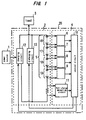
- a power supply apparatus 30 comprises a battery unit 32 for supplying an electric power to a load 33 such as a motor, and control and monitor means 34 for controlling and monitoring the battery unit 32.
- a raise in inner pressure of each battery in charging can be suppressed if the charging rate is set to 0.3 C or lower.
- the object secondary battery is a nickel-metal hydride storage battery, a significant effect can be obtained since monitoring the state of the battery becomes easy.
- the preset value of such charging or discharging amount is changed when the variance monitored by the control unit becomes higher than a predetermined value.
- the present invention can improve a reliability of a power supply apparatus significantly.
- the effect of the present invention will be more marked especially when the power supply apparatus is used for an electric vehicle or the like which needs an output with large capacity.
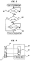
- the full-charge detecting circuit 11 detects the total voltage of the secondary batteries 5 and judges whether the secondary batteries 5 are charged up to the upper limit capacity or a normal full-charging value based on the detected value.
- the corrected upper limit capacity C cc is set larger by 30% than the upper limit capacity C c in the above embodiment, to set still larger C cc value arises a trouble from overcharge. On the other hand, if the C cc is set smaller than the value, however, the above effect is lessened.
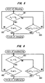
- the control circuit 10 judges the discharging to be done normally and outputs a signal for finishing the discharging to the discharging circuit 13. The discharging is thus finished normally. If the ⁇ d value is over the D d value, however, it replaces the lower limit capacity (C d ) with a smaller corrected lower limit capacity (C dc ) and continues the discharging. The discharging is finished after discharging until the total charged amount of the secondary batteries 5 drops to the C dc value.
Landscapes
- Engineering & Computer Science (AREA)
- Power Engineering (AREA)
- Physics & Mathematics (AREA)
- General Physics & Mathematics (AREA)
- Charge And Discharge Circuits For Batteries Or The Like (AREA)
- Secondary Cells (AREA)
- Electric Propulsion And Braking For Vehicles (AREA)
- Tests Of Electric Status Of Batteries (AREA)
Applications Claiming Priority (5)
| Application Number | Priority Date | Filing Date | Title |
|---|---|---|---|
| JP4041197 | 1997-02-25 | ||
| JP4041197 | 1997-02-25 | ||
| JP9335333A JPH10304588A (ja) | 1997-02-25 | 1997-12-05 | 電源装置 |
| JP33533397 | 1997-12-05 | ||
| PCT/JP1998/000743 WO1998038721A1 (fr) | 1997-02-25 | 1998-02-23 | Dispositif d'alimentation en energie |
Publications (3)
| Publication Number | Publication Date |
|---|---|
| EP0926799A1 true EP0926799A1 (fr) | 1999-06-30 |
| EP0926799A4 EP0926799A4 (fr) | 2002-10-16 |
| EP0926799B1 EP0926799B1 (fr) | 2003-11-26 |
Family
ID=26379877
Family Applications (1)
| Application Number | Title | Priority Date | Filing Date |
|---|---|---|---|
| EP98904431A Expired - Lifetime EP0926799B1 (fr) | 1997-02-25 | 1998-02-23 | Dispositif d'alimentation en energie |
Country Status (7)
| Country | Link |
|---|---|
| US (1) | US6054840A (fr) |
| EP (1) | EP0926799B1 (fr) |
| JP (1) | JPH10304588A (fr) |
| KR (2) | KR100338293B1 (fr) |
| CN (1) | CN1104771C (fr) |
| DE (1) | DE69820017T2 (fr) |
| WO (1) | WO1998038721A1 (fr) |
Cited By (1)
| Publication number | Priority date | Publication date | Assignee | Title |
|---|---|---|---|---|
| EP0909001A3 (fr) * | 1997-10-13 | 2000-04-05 | Toyota Jidosha Kabushiki Kaisha | Méthode et dispositif pour détecter l'état de charge d'un assemblage de batterie, et dispositif de commande de charge et décharge d'un assemblage de batterie |
Families Citing this family (41)
| Publication number | Priority date | Publication date | Assignee | Title |
|---|---|---|---|---|
| JP4567109B2 (ja) * | 1998-11-24 | 2010-10-20 | パナソニック株式会社 | 二次電池の充放電制御方法 |
| JP3676134B2 (ja) * | 1998-11-30 | 2005-07-27 | 三洋電機株式会社 | 充放電制御方法 |
| JP2000166103A (ja) * | 1998-12-01 | 2000-06-16 | Sanyo Electric Co Ltd | 充放電制御方法 |
| JP3988324B2 (ja) * | 1999-07-02 | 2007-10-10 | 株式会社デンソー | 組電池の異常判定装置及び組電池の異常判定方法 |
| JP4503746B2 (ja) * | 1999-11-18 | 2010-07-14 | フジテック株式会社 | 交流エレベータの電源装置 |
| JP4503749B2 (ja) * | 1999-12-13 | 2010-07-14 | フジテック株式会社 | 交流エレベータの電源装置 |
| JP3839761B2 (ja) * | 2001-09-14 | 2006-11-01 | 松下電器産業株式会社 | バッテリ制御装置 |
| JP3615507B2 (ja) * | 2001-09-28 | 2005-02-02 | 三洋電機株式会社 | 組電池の充電率調整回路 |
| JP2005110337A (ja) * | 2003-09-26 | 2005-04-21 | Sanyo Electric Co Ltd | 複数の電池の充電装置 |
| JP4843924B2 (ja) * | 2004-09-10 | 2011-12-21 | 日産自動車株式会社 | 組電池の容量調整装置 |
| JP4548289B2 (ja) * | 2005-09-26 | 2010-09-22 | 日産自動車株式会社 | 組電池の容量調整装置 |
| US8846224B2 (en) * | 2006-10-16 | 2014-09-30 | Lg Chem, Ltd. | High power secondary battery system comprising asymmetric charged cells |
| ATE549756T1 (de) * | 2006-10-16 | 2012-03-15 | Lg Chemical Ltd | Hochleistungs-sekundärbatteriesystem mit asymmetrischen geladenen zellen |
| JP4764324B2 (ja) * | 2006-12-25 | 2011-08-31 | 株式会社東芝 | エネルギー均等化装置 |
| JP4871180B2 (ja) * | 2007-03-20 | 2012-02-08 | 富士重工業株式会社 | 蓄電デバイスの制御装置 |
| US8309259B2 (en) * | 2008-05-19 | 2012-11-13 | Arizona Board Of Regents For And On Behalf Of Arizona State University | Electrochemical cell, and particularly a cell with electrodeposited fuel |
| JP5521044B2 (ja) * | 2009-09-18 | 2014-06-11 | フルイディック,インク. | 充電極を備え,セル内で充電モードと放電モードとを切り替える充電式電気化学セルシステム |
| MX2012004237A (es) * | 2009-10-08 | 2012-10-03 | Fluidic Inc | Celda metalica-aire recargable con sistema de manejo de flujo. |
| CN102544638B (zh) | 2010-06-24 | 2015-07-15 | 流体股份有限公司 | 具有阶梯形支架燃料阳极的电化学电池 |
| CN105206789B (zh) | 2010-09-16 | 2018-09-07 | 流体公司 | 具有渐进析氧电极/燃料电极的电化学电池系统 |
| ES2549592T3 (es) | 2010-10-20 | 2015-10-29 | Fluidic, Inc. | Procesos de reinicio de batería para electrodo de combustible en armazón |
| JP5908251B2 (ja) | 2010-11-17 | 2016-04-26 | フルイディック,インク.Fluidic,Inc. | 階層型アノードのマルチモード充電 |
| DE102011010585B4 (de) | 2011-02-08 | 2019-01-03 | Audi Ag | Verfahren zum Überwachen der Nutzung eines elektrochemischen Energiespeichers in einem Kraftfahrzeug, sowie Kraftfahrzeug |
| JP5533725B2 (ja) * | 2011-02-17 | 2014-06-25 | トヨタ自動車株式会社 | 車両の充電装置 |
| JP5533724B2 (ja) * | 2011-02-17 | 2014-06-25 | トヨタ自動車株式会社 | 車両の充電装置 |
| KR101916970B1 (ko) * | 2013-01-22 | 2018-11-08 | 삼성에스디아이 주식회사 | 배터리 관리 시스템 및 그를 포함하는 배터리 팩 |
| KR101509895B1 (ko) * | 2013-06-28 | 2015-04-06 | 현대자동차주식회사 | 배터리 파워 제한방법 |
| KR102565272B1 (ko) * | 2016-01-04 | 2023-08-09 | 삼성전자주식회사 | 배터리 관리 방법 및 배터리 관리 장치 |
| WO2017129259A1 (fr) * | 2016-01-29 | 2017-08-03 | Toyota Motor Europe Nv/Sa | Dispositif et procédé de commande pour décharger une batterie rechargeable |
| CN105490356A (zh) * | 2016-02-26 | 2016-04-13 | 联想(北京)有限公司 | 电子设备及其控制方法 |
| MX2019000905A (es) | 2016-07-22 | 2019-10-02 | Nantenergy Inc | Sistema de eliminacion de neblina para celdas electroquimicas. |
| CN109478643B (zh) | 2016-07-22 | 2022-03-15 | 南特能源公司 | 电化学电池中的水分和二氧化碳管理系统 |
| EP3513477B8 (fr) | 2016-09-15 | 2021-05-26 | Form Energy, Inc. | Système de batterie hybride |
| AU2017345601B2 (en) | 2016-10-21 | 2020-01-02 | Nantenergy, Inc. | Corrugated fuel electrode |
| JP2018152285A (ja) * | 2017-03-14 | 2018-09-27 | 株式会社東芝 | 蓄電池パック |
| JP6970289B2 (ja) * | 2018-05-31 | 2021-11-24 | 本田技研工業株式会社 | 充電制御装置、輸送機器、及びプログラム |
| CN120184457A (zh) | 2018-06-29 | 2025-06-20 | 福恩能源公司 | 金属空气电化学电池构架 |
| CN119481486A (zh) | 2018-06-29 | 2025-02-18 | 福恩能源公司 | 滚动膜片密封件 |
| WO2020231718A1 (fr) | 2019-05-10 | 2020-11-19 | Nantenergy, Inc. | Pile métal-air annulaire imbriquée et systèmes contenant celle-ci |
| WO2020264344A1 (fr) | 2019-06-28 | 2020-12-30 | Form Energy Inc. | Architectures de dispositif pour batteries métal-air |
| EP4147296A4 (fr) | 2020-05-06 | 2025-08-13 | Form Energy Inc | Système d'accumulation d'énergie électrochimique à électrode découplée |
Family Cites Families (12)
| Publication number | Priority date | Publication date | Assignee | Title |
|---|---|---|---|---|
| JP2530717B2 (ja) * | 1989-05-31 | 1996-09-04 | シャープ株式会社 | 電池電圧判別回路 |
| JP3429511B2 (ja) * | 1992-05-28 | 2003-07-22 | 東芝電池株式会社 | 二次電池の充電回路 |
| JPH0660910A (ja) * | 1992-08-12 | 1994-03-04 | Nec Corp | 充電システム |
| JP3096535B2 (ja) * | 1993-02-01 | 2000-10-10 | 三洋電機株式会社 | 二次電池の充電方法及び充電装置 |
| JPH06133465A (ja) * | 1992-08-27 | 1994-05-13 | Sanyo Electric Co Ltd | 二次電池の充電方法及び充電装置 |
| JP2903896B2 (ja) * | 1992-09-22 | 1999-06-14 | 日本電気株式会社 | リフレッシュ要求機能付電源 |
| JP3133534B2 (ja) * | 1993-01-29 | 2001-02-13 | 三洋電機株式会社 | 電池の過充電過放電防止方法 |
| JPH07143680A (ja) * | 1993-11-16 | 1995-06-02 | Matsushita Electric Ind Co Ltd | 充電器 |
| JPH07231571A (ja) * | 1994-02-14 | 1995-08-29 | Toshiba Corp | メモリ効果の除去装置 |
| JPH08140209A (ja) * | 1994-11-11 | 1996-05-31 | Fuji Heavy Ind Ltd | 電気自動車のバッテリ管理システム |
| JP3496311B2 (ja) * | 1994-12-14 | 2004-02-09 | 松下電工株式会社 | 充電式電気機器 |
| JP3435613B2 (ja) * | 1994-12-26 | 2003-08-11 | 日産自動車株式会社 | 組電池の充電装置 |
-
1997
- 1997-12-05 JP JP9335333A patent/JPH10304588A/ja active Pending
-
1998
- 1998-02-23 EP EP98904431A patent/EP0926799B1/fr not_active Expired - Lifetime
- 1998-02-23 DE DE69820017T patent/DE69820017T2/de not_active Expired - Lifetime
- 1998-02-23 KR KR1019980708541A patent/KR100338293B1/ko not_active Expired - Lifetime
- 1998-02-23 CN CN98800185A patent/CN1104771C/zh not_active Expired - Lifetime
- 1998-02-23 WO PCT/JP1998/000743 patent/WO1998038721A1/fr not_active Ceased
- 1998-02-23 US US09/171,731 patent/US6054840A/en not_active Expired - Lifetime
- 1998-10-24 KR KR1019980708541A patent/KR20000030274A/ko not_active Expired - Lifetime
Cited By (2)
| Publication number | Priority date | Publication date | Assignee | Title |
|---|---|---|---|---|
| EP0909001A3 (fr) * | 1997-10-13 | 2000-04-05 | Toyota Jidosha Kabushiki Kaisha | Méthode et dispositif pour détecter l'état de charge d'un assemblage de batterie, et dispositif de commande de charge et décharge d'un assemblage de batterie |
| US6104166A (en) * | 1997-10-13 | 2000-08-15 | Toyota Jidosha Kabushiki Kaisha | Method and device for detecting a state of charge of a battery assembly, and battery assembly charge and discharge control device |
Also Published As
| Publication number | Publication date |
|---|---|
| KR20000065006A (ko) | 2000-11-06 |
| WO1998038721A1 (fr) | 1998-09-03 |
| DE69820017T2 (de) | 2004-06-03 |
| KR20000030274A (en) | 2000-06-05 |
| KR100338293B1 (ko) | 2002-08-28 |
| CN1104771C (zh) | 2003-04-02 |
| CN1217832A (zh) | 1999-05-26 |
| US6054840A (en) | 2000-04-25 |
| EP0926799A4 (fr) | 2002-10-16 |
| JPH10304588A (ja) | 1998-11-13 |
| EP0926799B1 (fr) | 2003-11-26 |
| DE69820017D1 (de) | 2004-01-08 |
Similar Documents
| Publication | Publication Date | Title |
|---|---|---|
| EP0926799B1 (fr) | Dispositif d'alimentation en energie | |
| KR102949540B1 (ko) | 배터리 관리 시스템, 배터리 팩, 전기 차량 및 배터리 관리 방법 | |
| JP7169497B2 (ja) | バッテリー管理装置 | |
| JP7119262B2 (ja) | バッテリー管理装置 | |
| US8179139B2 (en) | Rechargeable battery abnormality detection apparatus and rechargeable battery apparatus | |
| US20130311119A1 (en) | Method of detecting battery full-charge capacity | |
| JP2000092732A (ja) | 組電池のばらつき判定方法及びバッテリ装置 | |
| US20080164849A1 (en) | Charging regime at any state of charge using the first derivative of temperature and the first and second derivative of voltage with respect to time | |
| KR100341754B1 (ko) | 전기 자동차의 배터리 충전 제어 방법 | |
| CN103548233A (zh) | 蓄电器控制电路 | |
| JPH1197074A (ja) | 充電方法及び充電装置 | |
| KR102763130B1 (ko) | 배터리 팩의 상태 진단 장치 및 방법 | |
| US20110025272A1 (en) | Charging method, charging device, and battery pack | |
| JPWO2012140776A1 (ja) | 充電制御装置 | |
| EP1340992B1 (fr) | Méthode et appareil pour le contrôle de la charge et décharge d'un bloc d'accumulateurs | |
| JP2003516607A (ja) | 鉛蓄電池用電荷維持システム | |
| KR102875759B1 (ko) | 배터리 관리 시스템 및 배터리 셀의 과전압 판단 방법 | |
| WO1993010590A1 (fr) | Systeme de gestion d'accumulateur | |
| US7612540B2 (en) | Lithium-ion battery diagnostic and prognostic techniques | |
| JP3157688B2 (ja) | 組電池の充電制御方法及び充電制御装置 | |
| JP2000050516A (ja) | 過充電防止回路、過放電防止回路及び充放電制御回路 | |
| JPH11313445A (ja) | 鉛蓄電池の充電方法およびその装置 | |
| KR102548137B1 (ko) | 배터리관리방법 및 배터리관리시스템 | |
| EP4207547A1 (fr) | Dispositif et procédé de prévention de surdécharge | |
| JP2002170599A (ja) | 監視装置、制御装置及び電池モジュール |
Legal Events
| Date | Code | Title | Description |
|---|---|---|---|
| PUAI | Public reference made under article 153(3) epc to a published international application that has entered the european phase |
Free format text: ORIGINAL CODE: 0009012 |
|
| 17P | Request for examination filed |
Effective date: 19981023 |
|
| AK | Designated contracting states |
Kind code of ref document: A1 Designated state(s): DE FR GB |
|
| RAP1 | Party data changed (applicant data changed or rights of an application transferred) |
Owner name: MATSUSHITA ELECTRIC INDUSTRIAL CO., LTD. |
|
| RTI1 | Title (correction) |
Free format text: POWER SUPPLY APPARATUS |
|
| A4 | Supplementary search report drawn up and despatched |
Effective date: 20020902 |
|
| AK | Designated contracting states |
Kind code of ref document: A4 Designated state(s): DE FR GB |
|
| RIC1 | Information provided on ipc code assigned before grant |
Free format text: 7H 02J 7/02 A, 7H 01M 10/44 B, 7H 02J 7/00 B |
|
| 17Q | First examination report despatched |
Effective date: 20021211 |
|
| GRAH | Despatch of communication of intention to grant a patent |
Free format text: ORIGINAL CODE: EPIDOS IGRA |
|
| GRAS | Grant fee paid |
Free format text: ORIGINAL CODE: EPIDOSNIGR3 |
|
| GRAA | (expected) grant |
Free format text: ORIGINAL CODE: 0009210 |
|
| AK | Designated contracting states |
Kind code of ref document: B1 Designated state(s): DE FR GB |
|
| REG | Reference to a national code |
Ref country code: GB Ref legal event code: FG4D |
|
| REF | Corresponds to: |
Ref document number: 69820017 Country of ref document: DE Date of ref document: 20040108 Kind code of ref document: P |
|
| ET | Fr: translation filed | ||
| PLBE | No opposition filed within time limit |
Free format text: ORIGINAL CODE: 0009261 |
|
| STAA | Information on the status of an ep patent application or granted ep patent |
Free format text: STATUS: NO OPPOSITION FILED WITHIN TIME LIMIT |
|
| 26N | No opposition filed |
Effective date: 20040827 |
|
| PGFP | Annual fee paid to national office [announced via postgrant information from national office to epo] |
Ref country code: FR Payment date: 20100223 Year of fee payment: 13 |
|
| PGFP | Annual fee paid to national office [announced via postgrant information from national office to epo] |
Ref country code: GB Payment date: 20100202 Year of fee payment: 13 |
|
| GBPC | Gb: european patent ceased through non-payment of renewal fee |
Effective date: 20110223 |
|
| REG | Reference to a national code |
Ref country code: FR Ref legal event code: ST Effective date: 20111102 |
|
| PG25 | Lapsed in a contracting state [announced via postgrant information from national office to epo] |
Ref country code: FR Free format text: LAPSE BECAUSE OF NON-PAYMENT OF DUE FEES Effective date: 20110228 |
|
| PG25 | Lapsed in a contracting state [announced via postgrant information from national office to epo] |
Ref country code: GB Free format text: LAPSE BECAUSE OF NON-PAYMENT OF DUE FEES Effective date: 20110223 |
|
| PGFP | Annual fee paid to national office [announced via postgrant information from national office to epo] |
Ref country code: DE Payment date: 20170214 Year of fee payment: 20 |
|
| REG | Reference to a national code |
Ref country code: DE Ref legal event code: R071 Ref document number: 69820017 Country of ref document: DE |