EP0926841A2 - Procédé et appareil d'essai de liaisons de communication - Google Patents
Procédé et appareil d'essai de liaisons de communication Download PDFInfo
- Publication number
- EP0926841A2 EP0926841A2 EP98309871A EP98309871A EP0926841A2 EP 0926841 A2 EP0926841 A2 EP 0926841A2 EP 98309871 A EP98309871 A EP 98309871A EP 98309871 A EP98309871 A EP 98309871A EP 0926841 A2 EP0926841 A2 EP 0926841A2
- Authority
- EP
- European Patent Office
- Prior art keywords
- test
- signal
- test signal
- telecommunications link
- exchange
- Prior art date
- Legal status (The legal status is an assumption and is not a legal conclusion. Google has not performed a legal analysis and makes no representation as to the accuracy of the status listed.)
- Withdrawn
Links
Images


Classifications
-
- H—ELECTRICITY
- H04—ELECTRIC COMMUNICATION TECHNIQUE
- H04B—TRANSMISSION
- H04B3/00—Line transmission systems
- H04B3/02—Details
- H04B3/46—Monitoring; Testing
Definitions
- This invention relates, in general, to a method of and apparatus for testing a telecommunications link and is particularly, but not exclusively, applicable to a method of and apparatus for testing a copper pair connecting a telephone exchange to a subscriber unit and especially for forming an assessment of the operational capabilities of the copper pair to support relatively high frequency broadband services.
- connection between individual telephone subscribers, be they domestic or business subscribers, and a local telephone exchange has traditionally been provided using copper cables consisting of a number of twisted-pair wires known as copper pairs. When these copper pairs were first deployed in local areas it was assumed that they would be used for transmission of voice signals only. These connections were expected to operate in a frequency range less than 4 kHz. Therefore, the planning rules which were adopted were based on easily controlled and measured parameters such as loop resistance and low frequency attenuation. In the UK the normal planning limits are 1000 Ohms loop resistance and 10 dB attenuation at 1 kHz.
- signal transmission in cable is principally through the so-called “skin effect” while loss (i.e. signal attenuation) is also skin effect dependent. Specifically, loss is proportionally greater in smaller gauge cables.
- ADSL asynchronous digital subscriber line signalling
- HDSL high speed digital subscriber line signalling
- VDSL very high speed digital subscriber line signalling
- the connectors may include sections of aluminium, which will have different transmission characteristics to the copper sections. Aluminium was used in this way when copper prices made copper less economic than aluminium.
- One alternative approach is for operators to dispatch staff to a customer's premises to undertake one or a series of measurements of the copper cable and its performance. This is a time consuming and consequently expensive solution, especially if the customer decides not to take the service, or takes it only for a short period.
- a variation on this method is for the operator to take sample measurements of cable lengths and performances from the exchange to the local telephone cabinet, from where individual copper pairs are directed to individual subscribers. As the cables from the exchange to the cabinet are shared this would reduce the cost per customer line, but would only give an indication of a few of the copper pairs from the exchange. Equally this gives no indication of the length and performance of the copper drops from the cabinet into customer's premises. Therefore this method is again rather inaccurate.
- Time domain reflectometry is a technique primarily used for determining a discontinuity or breakage in a cable. However, this may be usable to test a link from an exchange to a subscriber unit. Unfortunately, this method is not conducive to copper pairs, as there can be many reflections from imperfections, spliced joints, etc., which may mask the ultimate reflection, if any, from the end of the cable. Also, although most telephones are quite well matched to the line, they may not produce a reflection at the point where it may be most useful. Equally, the number of telephones connected at a customer's premises, and hence the differing impedances produced, could cause spurious results. The main difficulty is that TDR measurements require a fast pulse to operate accurately. This is not possible with copper cables beyond a few hundred metres in length. Therefore, again this method is not appropriate.
- US-A-3 912 884 describes a real-time monitoring system for assessing directionality of information flow.
- a gated circuit configuration restricts, at any time, the flow of information through the monitoring device to a single direction.
- US-A-4 302 843 relates to a measuring system for assessing characteristics of a transmission path.
- the system synthesises and then inserts special test pulses into gaps in normal traffic transmissions, and requires access to both ends of the transmission path under test.
- US-A-4 639 557 describes a system for controlling the testing of lines from a remote location other than a host exchange. Specifically, a tester, located at the host exchange, is controlled by dual tone multiple frequency (DTMF) signals sent from the remote location using a standard telephone handset. The system therefore provides remote control of a test desk located at the exchange, with results obtained from test signals emanating from the test desk conveyed back to the telephone using synthesised voice.
- DTMF dual tone multiple frequency
- a method of testing a telecommunications link between an exchange and a subscriber unit comprising the steps of: causing the subscriber unit to emit a predetermined test signal which is transmitted along the telecommunications link to the exchange; analysing the test signal received at the exchange; and characterised in that the method comprises the step of: assessing an operational quality of the telecommunications link at relatively high broadband frequencies based on the signal received at the exchange when using as the predetermined test signal one of: i) a DTMF test signal transmitted within a relatively low audio frequency range; and ii) an accurately generated signal generated from a dongle placed in-line between the subscriber unit and the telecommunications link.
- a wireline test system comprising: a subscriber terminal having means arranged to initiate the generation of a test signal having predetermined characteristics; and a test centre remotely coupled to the subscriber terminal through a wireline communication resource that modifies the predetermined characteristics of the test signal, the test centre having determination means coupled to receive the test signal and characterised by: means arranged to assess an operational quality of the wireline communication resource at relatively high broadband frequencies based on the characteristics of the test signal received at the test centre and wherein the test signal is one of: i) a DTMF test signal transmitted within a relatively low audio frequency range; and ii) an accurately generated signal generated from a dongle placed in-line between the subscriber terminal and the wireline communication resource.
- the predetermined characteristic includes a power level that has a power fluctuation within a range of ⁇ 0.2dB.
- the in-line dongle generates test signals at frequencies relatively close to and preferably within a frequency band of a proposed broadband service.
- the preferred embodiments of the present invention advantageously provide an inexpensive and accurate method and apparatus for testing a telecommunications link between an exchange and a subscriber, which method is especially applicable in relation to an operator being able to assess the suitability of the telecommunication link for high frequency, broadband-type systems.
- the method of testing telecommunications link does not require an engineer to visit a subscriber.
- the method of testing the link can be instigated from a subscriber's telephone enquiry and, as such, can be carried out as part of a single telephone call.
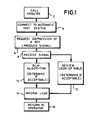
- FIG. 1 illustrates a method of testing a telecommunications link between a subscriber unit 20 and an exchange 30 ( Figure 2).
- the method is actuated due to a call from a subscriber as detailed in box 2 of the flow chart.
- the operator then connects the call to an automatic test system as indicated in box 4 of the flow chart.
- the method comprises the step of causing the subscriber unit 20 (FIG. 2) to emit a predetermined signal.
- the signal is produced by the subscriber depressing a key 22 on a keypad 24 on the subscriber unit 20. This step is indicated at box 6 on the flow chart.
- the signal thus produced is transmitted along the link 26, in the form of a copper pair, between the subscriber unit and the exchange 30.
- the predetermined test signal emitted by the subscriber unit 20 is thus connected to a receiver 32 within the test apparatus 18 from where it is transmitted to an analyser 34 for analysis such that a determination regarding the quality of the telecommunications link can be made based on the received signal.
- the entire process is controlled by a control means 36.
- the signal is produced by a dual tone multi-frequency (DTMF) telephone in which each of the keys produces a signal which is well specified for example in the UK in terms of frequency and relative amplitude.
- the frequency of each tone within the dual tone produced by each key is, preferably, controlled to an absolute accuracy, with a difference between high and low tones usually stipulated as being within 2dB.
- the levels for the tones may vary, e.g. within a range of 4dB for loop currents between 25 milliamps (mA) and 40mA, while in higher loop currents the levels may vary monotonically to 14dB at 125mA.
- Each DTMF subscriber unit 20 provides sixteen tones per combination, defined using numbers 0 to 9, *, # and letters A to D.
- the determination made regarding the quality of the link can either be a determination of the link quality in the audio band or it can be a projection of the estimated link quality when supporting broadband or wideband telecommunications signals.
- the method may include signature analysis in either the frequency domain or time domain (or both) which may be utilised to project broadband characteristics of the link.
- a look-up table is formed from empirical data which is obtained using known links for which both audio and wideband or broadband frequencies are monitored such that, when a particular audio frequency signal is received during use, a corresponding broadband or wideband result can be obtained from the look-up table and a determination made regarding the quality of the specific link being tested for the provision of broadband or wideband services.
- the method may include the running of an algorithm which is provided to project the expected behaviour of the link with broadband or wideband signals from the received audio frequency signal.
- Wideband and broadband signals include ISDN, HDSL, ADSL and VDSL signals.
- the proposed testing equipment uses digital signal processing (DSP) to analyse the waveform received at the exchange after the connected customer has pressed a key, as instructed by the test apparatus.
- DSP digital signal processing
- the composite waveform arriving at the exchange will have been modified by the copper pair between the customer and the exchange in a manner that can be correlated with the propagation characteristics of the line.
- In the frequency domain there will be a reduction in the relative and absolute amplitudes of the two fundamental tones produced by the subscriber unit, whilst in the time domain there will be a finite group delay between the two tone bursts.
- One embodiment of the invention uses algorithms predicting the effect of the characteristics on the relative amplitude and group delay, which can be coded into the DSP unit so that the results of a given test can be translated back into line characteristics.
- test apparatus will need to incorporate a standard DTMF receiver function in order to confirm that the customer has pressed the correct key(s), before starting analysis of the waveform. It is noted that DTMF transmitter output is permitted to vary with line currents above 40mA and is unspecified below 25mA, and it is therefore important that the tests are performed with line currents in this range.
- the operator who is running the tests with the customer may be sited at a normal operator console or at a test-desk. In the latter case, it is possible that adjustments may be made to the customer's telephone line current that can then be specially set to a particular current in order to obtain the best performance from the customer's DTMF telephone.
- Analyser box 34 An implementation of the Analyser box 34 is to take the outputs from the receiver 32 and process them into a form whereby meaningful data concerning the characteristics of the subscriber's line may be made. This processing can take the received DTMF tones and their relative amplitudes and delays.
- This processing may produce either frequency or time domain data series, and can be either linear or non-linear.
- FFT fast fourier transform
- DSP digital signal processor
- a particular example of the non-linear case is to half-wave rectify the received time domain signals which has a special ability to extract lower frequencies from the received signals, as can be seen from the dual tone signal illustrated in FIG. 3. Because the frequency is lower than the two DTMF tones, its amplitude is less affected by the customer's copper pair and can therefore be used as a reference level for the analysis of the DTMF tones. This non-linear processing also produces higher frequency components which will be quite sensitive to the customer's cable characteristics. This may therefore be used for generating the required signature of the line.
- the method described above provides an effective mechanism for line assessment, the method can be improved further through the transmission of an accurately set (and hence predetermined) signal.
- the subscriber actuate a pulse transmission of known frequency and/or known phase and known power.
- a better assessment of the telecommunication link for broadband applications can be achieved by reducing uncertainty in the test signal.
- FIG. 5 a graph of attenuation over length as a function of frequency is shown.
- an effective propagation distance for a signal varies according to its frequency (principally as a consequence of the skin effect).
- the rate of attenuation in a link between the voice band and a high frequency band differs to an extent that can cause a false level of confidence with respect to an effective propagation distance.
- an ability of a telecommunication link to carry recoverable broadband signals, for example, above the voice band is not readily discernible from a test signal in the voice band.
- a preferred embodiment of the present invention contemplates the use of a fixed level device, typically realised within an automatic or manually activated dongle 60, as shown in FIG. 6.
- the dongle 60 which may also operate at one of a given number of fixed frequencies, is placed in-line with a telephone handset (or data terminal) 62, such that the dongle 60 both interfaces with the telephone handset 62 and couples directly to the copper pair (not shown).
- Assessment of the telecommunication link is therefore subject to some delay by the provision of a suitably configured dongle 60 to the test household or commercial residence, with the dongle potentially returnable to the operator after completion of the line assessment.
- step 6 of FIG. 1 may also relate to the requirement to depress a manual activation button on the dongle, an automatic system causes the dongle 60 to respond 70 to an incident (typically a tone) instruction from a keypad on the subscriber handset (i.e. the phone) by converting that tone into a corresponding but more accurately controlled test signal that can then be applied 72 to the transmission link under test.
- incident typically a tone
- a keypad on the subscriber handset i.e. the phone
- the dongle 60 can be either line-powered or battery powered, and preferably has a specified signal level with a variation of approximately ⁇ 0.2dB of an arbitrarily selected value. Similarly, the dongle preferably has a specified frequency output within a tolerance.
- the subscriber dials the system operator to access a test centre, typically realised in the terminal equipment.
- the subscriber then causes a test signal generated in the dongle 60 to be transmitted to the line card of the terminal equipment.
- the subscriber is instructed by the test centre to depress a key on the telephone keypad, which key depression is intercepted and suppressed by the dongle 60.
- the dongle 60 responds to the test centre by sending the predetermined test signal; this being an automatic operation.
- a subscriber can manually actuate the dongle upon instruction.
- the subscriber In response to the test centre instruction, manually actuates a switch 64 on the in-line dongle 60 to cause the test signal to be transmitted to the test centre.
- An analog-to-digital converter in a line card at the terminal equipment is configured to make a quantitative assessment of the received test signal over the dedicated link from, for example, the telephone handset 62.
- the AID converter in the customer's line card at the exchange can be used to take the requisite measurement without the operator having to provide additional equipment.
- the quantitative assessment is then compared with an acceptable threshold value stored in a look-up table, and the result logged by the operator. Therefore, provided that the received test signal is quantitatively assessed to be sufficient, the dedicated line to the subscriber is patched to an appropriate modem that allows xDSL transmissions (or the like) over the dedicated copper pair. In the event that the quantitative assessment fails, then the operator either notifies the subscriber, proposes more definitive measurements or ear-marks the line for replacement.
- the present invention contemplates the provision of a dongle having output frequencies in the xDSL frequency spectrum.
- the test station 18 can then specifically search for and analyse these high frequency transmissions (at, for example 1MHz) to better assess the suitability of the communication resource for xDSL-type transmissions.
Landscapes
- Engineering & Computer Science (AREA)
- Computer Networks & Wireless Communication (AREA)
- Signal Processing (AREA)
- Monitoring And Testing Of Exchanges (AREA)
Applications Claiming Priority (4)
| Application Number | Priority Date | Filing Date | Title |
|---|---|---|---|
| GB9726902 | 1997-12-20 | ||
| GB9726902A GB2332593A (en) | 1997-12-20 | 1997-12-20 | A method of testing a telecommunications link |
| GB9811984 | 1998-06-05 | ||
| GBGB9811984.5A GB9811984D0 (en) | 1997-12-20 | 1998-06-05 | Method and apparatus for testing a telecommunications link |
Publications (2)
| Publication Number | Publication Date |
|---|---|
| EP0926841A2 true EP0926841A2 (fr) | 1999-06-30 |
| EP0926841A3 EP0926841A3 (fr) | 2003-07-09 |
Family
ID=26312813
Family Applications (1)
| Application Number | Title | Priority Date | Filing Date |
|---|---|---|---|
| EP98309871A Withdrawn EP0926841A3 (fr) | 1997-12-20 | 1998-12-02 | Procédé et appareil d'essai de liaisons de communication |
Country Status (2)
| Country | Link |
|---|---|
| EP (1) | EP0926841A3 (fr) |
| CA (1) | CA2256576A1 (fr) |
Cited By (3)
| Publication number | Priority date | Publication date | Assignee | Title |
|---|---|---|---|---|
| EP1111808A1 (fr) * | 1999-12-21 | 2001-06-27 | Alcatel | Procédé et appareil de détermination des propriétés d'un canal de transmission |
| EP1309873B1 (fr) * | 2000-06-23 | 2007-08-29 | Actaris S.A.S. | Procede d'evaluation d'une liaison de communication, terminal et systeme pour la mise en oeuvre d'un tel procede |
| WO2008008015A3 (fr) * | 2006-07-11 | 2008-04-03 | Ericsson Telefon Ab L M | Estimation de la perte d'insertion d'une ligne de transmission |
Family Cites Families (3)
| Publication number | Priority date | Publication date | Assignee | Title |
|---|---|---|---|---|
| US4467148A (en) * | 1982-02-02 | 1984-08-21 | Network Control Corporation | Telephone line analyzer |
| US4639557A (en) * | 1985-09-27 | 1987-01-27 | Communications Technology Corporation | Remote testing system for electrical circuits |
| IES65204B2 (en) * | 1995-05-09 | 1995-10-04 | Markton Limited | Apparatus for providing access to a line test device for testing a characteristics of a telephone line of a telephone network |
-
1998
- 1998-12-02 EP EP98309871A patent/EP0926841A3/fr not_active Withdrawn
- 1998-12-18 CA CA 2256576 patent/CA2256576A1/fr not_active Abandoned
Cited By (6)
| Publication number | Priority date | Publication date | Assignee | Title |
|---|---|---|---|---|
| EP1111808A1 (fr) * | 1999-12-21 | 2001-06-27 | Alcatel | Procédé et appareil de détermination des propriétés d'un canal de transmission |
| US6865256B1 (en) | 1999-12-21 | 2005-03-08 | Alcatel | Method and apparatus for determining properties of a transmission channel |
| EP1309873B1 (fr) * | 2000-06-23 | 2007-08-29 | Actaris S.A.S. | Procede d'evaluation d'une liaison de communication, terminal et systeme pour la mise en oeuvre d'un tel procede |
| WO2008008015A3 (fr) * | 2006-07-11 | 2008-04-03 | Ericsson Telefon Ab L M | Estimation de la perte d'insertion d'une ligne de transmission |
| US8265232B2 (en) | 2006-07-11 | 2012-09-11 | Telefonaktiebolaget Lm Ericsson (Publ) | Estimation of transmission line insertion loss |
| CN101490970B (zh) * | 2006-07-11 | 2013-01-02 | 艾利森电话股份有限公司 | 传输线插入损耗的估计 |
Also Published As
| Publication number | Publication date |
|---|---|
| CA2256576A1 (fr) | 1999-06-20 |
| EP0926841A3 (fr) | 2003-07-09 |
Similar Documents
| Publication | Publication Date | Title |
|---|---|---|
| US6895081B1 (en) | Predicting performance of telephone lines for data services | |
| US6975706B1 (en) | Capacitance measurement-based mechanism for locating open telecommunication line fault | |
| KR100404240B1 (ko) | 광대역 서비스를 지원하기 위해 가입자 회선의 기능을평가하는 방법 및 시스템 | |
| US6014425A (en) | Apparatus and method for qualifying telephones and other attached equipment for optimum DSL operation | |
| US6373923B1 (en) | Line testing method and apparatus therefor | |
| US5875230A (en) | Interactive measurement system and method for telecommunication networks | |
| US7027405B1 (en) | System and method for broadband analysis of telephone local loop | |
| US5410585A (en) | Subscriber line test system | |
| US6894504B2 (en) | Technique for estimation of a subscriber line insertion loss | |
| US7224672B2 (en) | XDSL modem | |
| US6341159B1 (en) | Extrapolation of location and amplitude of noise sources on telecommunication wireline from ended access point | |
| US6459773B1 (en) | System to pre-qualify copper subscriber loops for high bandwidth access service using subscriber or network generated tones | |
| EP0926841A2 (fr) | Procédé et appareil d'essai de liaisons de communication | |
| US6584177B2 (en) | Monitoring device and method for monitoring a telecommunication network | |
| US6628756B2 (en) | System and method for telephone number verification and identification | |
| GB2332593A (en) | A method of testing a telecommunications link | |
| EP2501113A1 (fr) | TDR d'appareil d'essai téléphonique | |
| US12513240B2 (en) | Detecting modem power state change | |
| US6782078B1 (en) | System to pre-qualify copper subscriber loops for high bandwidth access service using subscriber voice signals | |
| US20070189464A1 (en) | Method for distributing hardware and software resources for high bit rate link control | |
| KR20010056355A (ko) | 비대칭 디지털 가입자 선로 시험 방법 및 장치 | |
| US20120237001A1 (en) | Phone test set tdr | |
| KR100214311B1 (ko) | 전화선로 상태 측정장치 | |
| KR100311150B1 (ko) | 전기 통신 선로의 비트 에러 시험 장치 | |
| MXPA00009476A (en) | Method and system for estimating the ability of a subscriber loop to support broadband services |
Legal Events
| Date | Code | Title | Description |
|---|---|---|---|
| PUAI | Public reference made under article 153(3) epc to a published international application that has entered the european phase |
Free format text: ORIGINAL CODE: 0009012 |
|
| AK | Designated contracting states |
Kind code of ref document: A2 Designated state(s): AT BE CH CY DE DK ES FI FR GB GR IE IT LI LU MC NL PT SE |
|
| AX | Request for extension of the european patent |
Free format text: AL;LT;LV;MK;RO;SI |
|
| RAP3 | Party data changed (applicant data changed or rights of an application transferred) |
Owner name: NORTEL NETWORKS CORPORATION |
|
| RAP1 | Party data changed (applicant data changed or rights of an application transferred) |
Owner name: NORTEL NETWORKS LIMITED |
|
| PUAL | Search report despatched |
Free format text: ORIGINAL CODE: 0009013 |
|
| AK | Designated contracting states |
Designated state(s): AT BE CH CY DE DK ES FI FR GB GR IE IT LI LU MC NL PT SE |
|
| AX | Request for extension of the european patent |
Extension state: AL LT LV MK RO SI |
|
| RIC1 | Information provided on ipc code assigned before grant |
Ipc: 7H 04B 3/48 B Ipc: 7H 04B 3/46 A |
|
| STAA | Information on the status of an ep patent application or granted ep patent |
Free format text: STATUS: THE APPLICATION HAS BEEN WITHDRAWN |
|
| RAP1 | Party data changed (applicant data changed or rights of an application transferred) |
Owner name: NORTEL NETWORKS LIMITED |
|
| 18W | Application withdrawn |
Effective date: 20030910 |