EP0926858B1 - Procédé de synchronisation d'un récepteur sur des données numériques transmises par paquets - Google Patents
Procédé de synchronisation d'un récepteur sur des données numériques transmises par paquets Download PDFInfo
- Publication number
- EP0926858B1 EP0926858B1 EP19980403213 EP98403213A EP0926858B1 EP 0926858 B1 EP0926858 B1 EP 0926858B1 EP 19980403213 EP19980403213 EP 19980403213 EP 98403213 A EP98403213 A EP 98403213A EP 0926858 B1 EP0926858 B1 EP 0926858B1
- Authority
- EP
- European Patent Office
- Prior art keywords
- time
- process according
- rate
- signals
- data
- Prior art date
- Legal status (The legal status is an assumption and is not a legal conclusion. Google has not performed a legal analysis and makes no representation as to the accuracy of the status listed.)
- Expired - Lifetime
Links
- 238000000034 method Methods 0.000 title claims description 15
- 238000004364 calculation method Methods 0.000 claims description 23
- 230000005540 biological transmission Effects 0.000 claims description 19
- 230000003111 delayed effect Effects 0.000 claims description 4
- 125000004122 cyclic group Chemical group 0.000 claims 1
- 238000005070 sampling Methods 0.000 description 8
- 230000033764 rhythmic process Effects 0.000 description 7
- 238000007476 Maximum Likelihood Methods 0.000 description 6
- 230000006870 function Effects 0.000 description 3
- 230000015654 memory Effects 0.000 description 3
- 238000011282 treatment Methods 0.000 description 3
- 238000004891 communication Methods 0.000 description 1
- 238000001514 detection method Methods 0.000 description 1
- 238000010586 diagram Methods 0.000 description 1
- 238000001914 filtration Methods 0.000 description 1
- 230000003071 parasitic effect Effects 0.000 description 1
- 239000012536 storage buffer Substances 0.000 description 1
- 230000002123 temporal effect Effects 0.000 description 1
Images


Classifications
-
- H—ELECTRICITY
- H04—ELECTRIC COMMUNICATION TECHNIQUE
- H04J—MULTIPLEX COMMUNICATION
- H04J3/00—Time-division multiplex systems
- H04J3/02—Details
- H04J3/06—Synchronising arrangements
- H04J3/0602—Systems characterised by the synchronising information used
- H04J3/0605—Special codes used as synchronising signal
- H04J3/0608—Detectors therefor, e.g. correlators, state machines
-
- H—ELECTRICITY
- H04—ELECTRIC COMMUNICATION TECHNIQUE
- H04L—TRANSMISSION OF DIGITAL INFORMATION, e.g. TELEGRAPHIC COMMUNICATION
- H04L7/00—Arrangements for synchronising receiver with transmitter
- H04L7/04—Speed or phase control by synchronisation signals
- H04L7/041—Speed or phase control by synchronisation signals using special codes as synchronising signal
- H04L7/042—Detectors therefor, e.g. correlators, state machines
-
- H—ELECTRICITY
- H04—ELECTRIC COMMUNICATION TECHNIQUE
- H04L—TRANSMISSION OF DIGITAL INFORMATION, e.g. TELEGRAPHIC COMMUNICATION
- H04L7/00—Arrangements for synchronising receiver with transmitter
- H04L7/0054—Detection of the synchronisation error by features other than the received signal transition
- H04L7/007—Detection of the synchronisation error by features other than the received signal transition detection of error based on maximum signal power, e.g. peak value, maximizing autocorrelation
Definitions
- the transmission of digital data through a network of communication is often done in packets.
- the network When the network is strictly transparent, it transmits the package as if it were a analogue signal, that is to say, it does not hold each period elementary bit of the packet on a possible network clock. It is for example the case when it comes to simple cables, used by for example, in an on-demand broadcast network of television, to transmit, to the head station, the requests of the subscribers.
- This transmission can be performed using a time frame according to the TDMA technique (Multiple Access by Time Division) in which is assigned a time slot to each user.
- the transmissions may also concern point-to-multipoint links such as only of the type LMDS (Local Multipoint Distribution System).
- a receiver must, in control circuits sample, first analyze the form of any signal received for recognize that it is a package and to determine a specific moment to begin to cyclically sample the signal, at determined rhythm of the transmission of the bits and, more generally, of symbols. It is therefore necessary to reproduce the clock used to the emission of the received symbols, and this with a corresponding delay exactly to the transmission, in order, on the one hand, to perform a logical synchronization to restore all the symbols of the packet in spotting the position of the first, and only these, and, secondly, to perform an analog synchronization, allowing you to read correctly each logical symbol state received.
- the synchronization analog requires stalling the sampling on the clock of transmission, taking into account the transmission delay, so that each symbol, whose reception has begun, is sampled with a delay enough to stabilize it and read it without error. Obviously, logical synchronization can only intervene if the analog synchronization is established.
- the invention relates to a method for synchronizing a receiver of digital data signals transmitted at a rate determined, by data packets preceded by a preamble in which a continuous treatment is carried out continuously.
- likelihood search for a block of signals comprising the preamble and data from the rest of the packet we memorize the signals received and when a maximum of likelihood is reached, a reading sampling, at the determined rate, of the data signals already received and memorized.
- the optimal time to sample a first logical symbol of the package can be determined with high precision since the maximum likelihood is based on an analysis that is only preamble, to extend over the data area itself.
- a stream of data power values is developed. start of packet and a flow of correlation values between the preamble predetermined and received preamble, by a continuous calculation of the values considered, and the flow of correlation values for add it to the power value stream and thus get a value of likelihood.
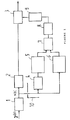
- the receiver of Figure 1 belongs to a headend station of a broadcast network on demand television programs and comprises an input stage 1 for filtering / demodulating a signal y (t), originating from a coaxial cable of a transmission network, for which a more detailed explanation is provided below.
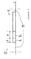
- the received signal y (t) corresponds to a sequence of subscriber requests, distributed in channels of a TDMA frame, selecting a particular program. Each request consists of a packet R of symbols with a predetermined preamble Pr of recognition and synchronization, of duration P.
- time interval IT When a subscriber wants to send a request, it is allocated to him a time interval IT, or time slot, in the time frame is repeating cyclically, the time interval IT having a duration equal to that of a packet R increased by a margin M, or guard interval, to tolerate fluctuations of the moment of emission of the packet R and take into account the transmission time.
- Input stage 1 provides a signal x (t) filtered in baseband at one delay circuit 2, as a delay line, which stores the signal on a duration P + D and restores it, with the delay P + D, to a circuit 3 reading sample, controlled by a time base circuit 9 to controlled triggering.
- the duration D is that of a data zone numerical Do, of the packet R, according to the preamble Pr.
- the signal x (t) is also applied at the input of a set 10 of control of the sampling circuit 3.
- the signal x (t) is applied to it at through a delay circuit 4 D, to a calculation block 5, calculating the correlation between the predetermined preamble Pr, and stored locally, and a received signal start area for detecting the Pr preamble.
- a calculation block 6 also receives, directly, the signal x (t) for determine the signal strength x (t) in the zone Do.
- Circuit 4 with delay D makes it possible to set the respective end times of the correlation calculation, duration P, and calculation of power, duration D, which is naturally delayed by the duration P since the data of the zone concerned are only transmitted after Pr preamble, so with a delay P.
- An adder 7 provides the sum of the results of the calculation blocks 5 and 6 to a maximum detection circuit 8 controlling the trigger of the time base 9.
- the two terms, or flows, added together may be weighted relative to one another according to system parameters of transmission.
- a treatment of likelihood search for the signal block of the packet R, block containing the preamble Pr and the data Do of the remainder of the packet R, the data signals Do of the block are memorized and, when a maximum likelihood is achieved, a reading sample is started at determined rhythm F, data signals C already received and stored and, where appropriate, those who follow.
- a block of values of power of the packet start data Do and in block 5 a stream correlation values between the predetermined preamble Pr and the preamble received, by a continuous calculation of the current values considered, the correlation value stream being delayed by D to add it to the flow of power values and thus obtain a likelihood value.
- the packages, of duration determined are transmitted, without coordination between them, in the respective time slots of the time frame, intervals of IT time of duration corresponding to that of a packet R increased by margin M.
- a specific synchronization is performed at each interval IT time in a time window starting at the beginning of it and including the margin M, that is to say that it is considered that the packet R can be stalled at the end of the time interval, the margin M being then in all before package R.
- the search for a maximum in the circuit 8 is carried out continuously, that is, the signal x (t) flows in the various circuits and it is analyzed throughout this flow.
- samples of the signal x (t) are quantified over a given number of bits, for example 10 bits.
- the interval 1 to L represents a time window of signal analysis received x (t), window that gradually passes through it as the time passes.
- the analysis window slides into a longer period of time (M + L), in which the beginning is expected of a package.
- the new current value S i + 1 of power is computed cyclically in the determined size time window L traversed by the signals x (t), by previously memorizing the previous value Si and correcting it as a function of the difference x n - x o of the powers of the two signal portions respectively entering and leaving the window L, a calculation to the next.
- the input signal is applied to a calculation unit 61 performing the above addition (S i) and is also applied through a circuit 62 to delay corresponding to the analysis window, a block calculation 63 similar to block 61.
- a subtractor 64 powered by circuits 61 and 63, supplies the value x n -x o to adder 65 whose output, which is that of block 6, is looped back through a row.
- K eight shift registers 66 advancing at the oversampling frequency Fs, corresponding to a total delay of a symbol period T.
- the power calculations are performed in steps at the oversampling frequency Fs multiple (K) the transmission rate F, cyclically affecting, at each calculation, a time slice in the period of the rhythm T, and restoring the previous value S i by delaying it by a number of steps equal to the multiple K and representing in total the period T.
- the adder 65 receives, to calculate S i + 1 , the delayed signal S i of T and the correction x n - x o desired.
- the detector 8 of maximum, or peak comprises a input comparator 81 and a multiplexer 82 with two channels receiving all two, at the oversampling frequency Fs, the new result of the adder 7 and the previous result coming from a delay circuit 83, delay equal to the period of the oversampling frequency Fs, here T / 8.
- the output of the comparator 81 controls the switching of the multiplexer 82 to apply the new result to the input of the delay circuit 83, current, as long as the analyzed signal coming from the adder 7, and, otherwise, the comparator 81 changes state to confirm the old result.
- the circuit 83 could be a controlled storage buffer register by a frequency clock Fs, in which case the multiplexer 82 could be replaced by a lock gate of the clock, the signal input from the adder 7 coming directly to the input of registry data.
- the above circuits can, if necessary, deal with numbers greater than ten bits, if the required precision requires it.
- the time base 9 has an oscillator with a much lower period at T, for example of frequency Fs, but then integer multiple of the transmission frequency F of the symbols of x (t).
- the instantaneous value is stored present at the output of the delay circuit 2, that is to say that the circuit 3 is here a clock input shift register connected to the output of a decoder of the state "1" of the counter of the time base 9.
- the delay circuit 2 is made in the form of a FIFO ring memory at frequency Fs, having at least the capacity for the desired delay, it should then be addressed to choose the desired symbol delay (position of the first symbol and subsequent ones) and more precisely choose that of the eight oversamples having, in the period T, the optimal phase for reading the symbol, that is to say a oversample level perfectly representing the emitted symbol.
- the signal x (t) is stored in analog form or in digital form after digitization by oversampling allowing to restore the shape. So we store the total shape, continuous signal x (t) received, without seeking to detect the symbols transmitted at frequency F, and only after the treatments above the sampling corresponding to the frequency F. the signal x (t) is stored, the time no longer plays directly and understands that the notion of frequency sampling F then encompasses the notion of spatial sampling in memory, among the oversample, at any time in relation to the rest of the R package data, which can be sampled as they arrive from circuit 1, without delay (2).
- each symbol would be represented by an evolutionary signal no baseband, it would be appropriate to locate in the circuit 2, according to the command of the time base 9, the eight oversamples of each symbol to transmit them grouped to the sampling circuit 3, for analysis, by demodulation to recognize the symbol.
Landscapes
- Engineering & Computer Science (AREA)
- Computer Networks & Wireless Communication (AREA)
- Signal Processing (AREA)
- Synchronisation In Digital Transmission Systems (AREA)
Description
- la figure 1 est un schéma par blocs d'un récepteur pour la mise en oeuvre du procédé de l'invention,
- la figure 2 représente, en fonction du temps t, un paquet de données dans un intervalle de temps d'une trame de transmission,
- la figure 3 illustre plus en détails, sous forme de blocs fonctionnels, un bloc de calcul de puissance, et
- la figure 4 illustre un circuit de détermination d'une valeur maximale dans une suite.
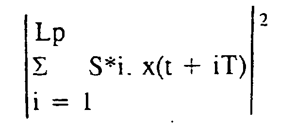
- i :
- rang du symbole dans le paquet, ici dans le préambule
- S*i
- : représentation complexe conjuguée du motif de symboles de préambule prédéterminé.
- Lp :
- nombre de symboles du préambule, ici = 16.
- t :
- instant courant.

L (ici : 252) : nombre de symboles du préambule Pr et de la zone Do, ce calcul ne portant donc que sur cette zone.
Claims (9)
- Procédé de synchronisation d'un récepteur de signaux de données numériques transmis, à un rythme déterminé (F), par paquets (R) de données précédées d'un préambule prédéterminé (Pr), dans lequel on effectue continûment un traitement de recherche de vraisemblance portant sur un bloc de signaux, comportant le préambule (Pr) et des données (Do) du reste du paquet (R), on mémorise (2) les signaux reçus et, lorsqu'un maximum de vraisemblance est atteint (8), on lance un échantillonnage de lecture (9), au rythme déterminé (F), des signaux de données déjà reçus et mémorisés (Do).
- Procédé selon la revendication 1, dans lequel on déduit directement, d'après l'instant auquel est atteint le maximum de vraisemblance, à la fois la phase des signaux reçus au dit rythme et la position temporelle des données dans ceux-ci.
- Procédé selon l'une des revendications 1 et 2, dans lequel on élabore (6) un flux de valeurs de puissance des données (Do) de début de paquet et un flux de valeurs de corrélation entre le préambule prédéterminé (Pr) et le préambule reçu, par un calcul continu des valeurs courantes considérées, et on retarde (4) le flux de valeurs de corrélation (5) pour l'additionner au flux de valeurs de puissance (6) et ainsi obtenir une valeur de vraisemblance.
- Procédé selon l'une des revendications 1 à 3, dans lequel, les paquets, de durée déterminée, étant transmis dans des intervalles de temps respectifs (IT), d'une trame temporelle, de durée correspondant à celle d'un paquet augmentée d'une marge (M), on effectue une synchronisation spécifique à chaque intervalle de temps (IT) dans une fenêtre temporelle commençant au début de celui-ci et incluant ladite marge (M).
- Procédé selon l'une des revendications 1 à 4, dans lequel on effectue la recherche de vraisemblance en prélevant, sur les signaux reçus, des échantillons pour la recherche de vraisemblance, à un rythme (Fs) supérieur au rythme de transmission F.
- Procédé selon l'une des revendications 3 à 5, dans lequel on calcule cycliquement une nouvelle valeur courante de puissance (Si + 1), dans une fenêtre temporelle de taille déterminée (L) que traversent les signaux, en mémorisant préalablement une valeur précédente (Si) et en la corrigeant en fonction de la différence (xn - xo) des puissances des deux tronçons de signaux respectivement entrés et sortis de la fenêtre (L), d'un calcul au suivant.
- Procédé selon la revendication 6, dans lequel on effectue les calculs à une fréquence de suréchantillonnage (Fs) multiple (K) du rythme de transmission (F), en affectant cycliquement, à chaque calcul, une tranche de temporelle dans la période (T) dudit rythme et on restitue la valeur précédente (Si) en la retardant d'un nombre de pas égal audit multiple (K) et représentant au total ladite période (T).
- Procédé selon l'une des revendications 3 à 7, dans lequel on détecte le maximum de vraisemblance par comparaisons cycliques (81) entre une valeur actuelle et une valeur précédente de la vraisemblance, pour à chaque fois sélectionner (82) la valeur la plus élevée et la mémoriser (83), et on détecte le maximum par le fait que la valeur précédente est à nouveau sélectionnée.
- Procédé selon l'une des revendications 3 à 8, dans lequel on pondère, l'un par rapport à l'autre, les deux flux avant de les additionner.
Applications Claiming Priority (2)
| Application Number | Priority Date | Filing Date | Title |
|---|---|---|---|
| FR9716324 | 1997-12-23 | ||
| FR9716324A FR2773029B1 (fr) | 1997-12-23 | 1997-12-23 | Procede de synchronisation d'un recepteur sur des donnees numeriques transmises par paquets |
Publications (2)
| Publication Number | Publication Date |
|---|---|
| EP0926858A1 EP0926858A1 (fr) | 1999-06-30 |
| EP0926858B1 true EP0926858B1 (fr) | 2005-10-19 |
Family
ID=9514974
Family Applications (1)
| Application Number | Title | Priority Date | Filing Date |
|---|---|---|---|
| EP19980403213 Expired - Lifetime EP0926858B1 (fr) | 1997-12-23 | 1998-12-18 | Procédé de synchronisation d'un récepteur sur des données numériques transmises par paquets |
Country Status (3)
| Country | Link |
|---|---|
| EP (1) | EP0926858B1 (fr) |
| DE (1) | DE69831922T2 (fr) |
| FR (1) | FR2773029B1 (fr) |
Families Citing this family (3)
| Publication number | Priority date | Publication date | Assignee | Title |
|---|---|---|---|---|
| GB9902755D0 (en) * | 1999-02-08 | 1999-03-31 | Simoco Int Ltd | Digital signal receiver synchronisation |
| EP1213872A3 (fr) * | 2000-12-05 | 2002-07-03 | Koninklijke Philips Electronics N.V. | Récupération d'un paquet dans un système de transmissions par paquets avec voie de retour |
| FR2928059B1 (fr) * | 2008-02-22 | 2016-01-08 | Thales Sa | Procede et dispositif de delineation d'un flux de donnees et systeme de communication comprenant ledit dispositif. |
Family Cites Families (4)
| Publication number | Priority date | Publication date | Assignee | Title |
|---|---|---|---|---|
| JPH0716206B2 (ja) * | 1988-08-05 | 1995-02-22 | 日本電気株式会社 | 信号検出器 |
| SE465005B (sv) * | 1989-11-15 | 1991-07-08 | Ericsson Telefon Ab L M | Foerfarande att bestaemma samplingstidpunkt |
| JPH06124545A (ja) * | 1992-08-25 | 1994-05-06 | Sony Corp | クロック信号の自動位相調整回路 |
| JPH0828754B2 (ja) * | 1993-06-30 | 1996-03-21 | 日本電気株式会社 | フレーム同期方式 |
-
1997
- 1997-12-23 FR FR9716324A patent/FR2773029B1/fr not_active Expired - Lifetime
-
1998
- 1998-12-18 EP EP19980403213 patent/EP0926858B1/fr not_active Expired - Lifetime
- 1998-12-18 DE DE1998631922 patent/DE69831922T2/de not_active Expired - Lifetime
Also Published As
| Publication number | Publication date |
|---|---|
| DE69831922T2 (de) | 2006-07-06 |
| DE69831922D1 (de) | 2006-03-02 |
| FR2773029A1 (fr) | 1999-06-25 |
| EP0926858A1 (fr) | 1999-06-30 |
| FR2773029B1 (fr) | 2000-02-04 |
Similar Documents
| Publication | Publication Date | Title |
|---|---|---|
| EP0856162B1 (fr) | Recepteur de determination d'une position a partir de reseaux de satellites | |
| EP1997035B1 (fr) | Procede et dispositif de calcul de correlation rapide | |
| EP0881804B1 (fr) | Procédé de détermination d'un format d'émission de symboles dans un système de transmission et système associé | |
| CH674435A5 (fr) | ||
| FR2758026A1 (fr) | Procede et systeme pour une demodulation en parallele de plusieurs impulsions de donnees d'un signal cdma | |
| EP0162174A1 (fr) | Dispositif tampon utilisé dans un réseau de transmission de la voix | |
| EP0298810B1 (fr) | Procédé et dispositif pour l'acquisition de bits de synchronisation dans des systèmes de transmission de données | |
| EP1041729A1 (fr) | Procédé de synchronisation de rythme d'un signal numérique | |
| EP0131521B1 (fr) | Procédé et installation d'analyse et de restitution de signal à échantillonnage et interpolation | |
| EP0926858B1 (fr) | Procédé de synchronisation d'un récepteur sur des données numériques transmises par paquets | |
| EP1094631B1 (fr) | Recherche de l'instant d'échantillonnage optimal dans un système de transmissions par paquets TDMA | |
| CA2209476C (fr) | Procede de commutation d'un canal d'un premier chemin de propagation vers un second chemin de propagation | |
| EP0283077B1 (fr) | Dispositif de décodage de signaux codés en duobinaire | |
| EP0056748A2 (fr) | Procédé de synchronisation à la réception de signaux numériques transmis par paquets | |
| FR2470494A1 (fr) | Procede et dispositif de changement de cadence d'un signal | |
| FR2643524A1 (fr) | Procede et dispositif de synchronisation bit dans un recepteur de transmission de donnees numeriques | |
| EP1135855B1 (fr) | Filtre numerique a architecture parallele et recepteur de signaux a etalement de spectre utilisant un tel filtre | |
| EP0737868B1 (fr) | Boucle à verrouillage de délai pour utilisation dans un récepteur de signaux GPS | |
| FR2724513A1 (fr) | Systeme de transmission numerique synchronisable sur ses sequences d'initialisation | |
| FR2781945A1 (fr) | Procede de codage convolutif et de transmission par paquets d'un flux serie de donnees numeriques, procede et dispositif de decodage correspondants | |
| FR2825550A1 (fr) | Dispositif et procede de demodulation numerique d'un signal recu par selection d'un filtre et recepteur de communication numerique le comportant | |
| EP1213872A2 (fr) | Récupération d'un paquet dans un système de transmissions par paquets avec voie de retour | |
| EP0295974B1 (fr) | Procédé et dispositif de décodage de signaux duobinaires émis par salves | |
| CA3008377A1 (fr) | Procedes et dispositifs de transmission de train binaire continu dans un reseau numerique non synchrone du train binaire | |
| EP2146457A1 (fr) | Procédé de synchronisation temporelle d'un signal numérique, dispositif et produit programme d'ordinateur correspondants |
Legal Events
| Date | Code | Title | Description |
|---|---|---|---|
| PUAI | Public reference made under article 153(3) epc to a published international application that has entered the european phase |
Free format text: ORIGINAL CODE: 0009012 |
|
| AK | Designated contracting states |
Kind code of ref document: A1 Designated state(s): DE GB IT |
|
| AX | Request for extension of the european patent |
Free format text: AL;LT;LV;MK;RO;SI |
|
| 17P | Request for examination filed |
Effective date: 19991221 |
|
| AKX | Designation fees paid |
Free format text: DE GB IT |
|
| 17Q | First examination report despatched |
Effective date: 20040824 |
|
| GRAP | Despatch of communication of intention to grant a patent |
Free format text: ORIGINAL CODE: EPIDOSNIGR1 |
|
| RAP1 | Party data changed (applicant data changed or rights of an application transferred) |
Owner name: SAGEM S.A. |
|
| GRAS | Grant fee paid |
Free format text: ORIGINAL CODE: EPIDOSNIGR3 |
|
| GRAA | (expected) grant |
Free format text: ORIGINAL CODE: 0009210 |
|
| AK | Designated contracting states |
Kind code of ref document: B1 Designated state(s): DE GB IT |
|
| REG | Reference to a national code |
Ref country code: GB Ref legal event code: FG4D Free format text: NOT ENGLISH |
|
| GBT | Gb: translation of ep patent filed (gb section 77(6)(a)/1977) |
Effective date: 20060111 |
|
| REF | Corresponds to: |
Ref document number: 69831922 Country of ref document: DE Date of ref document: 20060302 Kind code of ref document: P |
|
| PLBE | No opposition filed within time limit |
Free format text: ORIGINAL CODE: 0009261 |
|
| STAA | Information on the status of an ep patent application or granted ep patent |
Free format text: STATUS: NO OPPOSITION FILED WITHIN TIME LIMIT |
|
| 26N | No opposition filed |
Effective date: 20060720 |
|
| REG | Reference to a national code |
Ref country code: GB Ref legal event code: 732E Free format text: REGISTERED BETWEEN 20090319 AND 20090325 |
|
| REG | Reference to a national code |
Ref country code: GB Ref legal event code: 732E Free format text: REGISTERED BETWEEN 20090326 AND 20090401 |
|
| REG | Reference to a national code |
Ref country code: DE Ref legal event code: R082 Ref document number: 69831922 Country of ref document: DE Representative=s name: MAIWALD PATENTANWALTSGESELLSCHAFT MBH, DE Ref country code: DE Ref legal event code: R082 Ref document number: 69831922 Country of ref document: DE |
|
| REG | Reference to a national code |
Ref country code: DE Ref legal event code: R081 Ref document number: 69831922 Country of ref document: DE Owner name: SAGEMCOM ENERGY & TELECOM SAS, FR Free format text: FORMER OWNER: SAGEM S.A., PARIS, FR Effective date: 20120120 Ref country code: DE Ref legal event code: R081 Ref document number: 69831922 Country of ref document: DE Owner name: SAGEMCOM SAS, FR Free format text: FORMER OWNER: SAGEM S.A., PARIS, FR Effective date: 20120120 |
|
| REG | Reference to a national code |
Ref country code: DE Ref legal event code: R081 Ref document number: 69831922 Country of ref document: DE Owner name: SAGEMCOM ENERGY & TELECOM SAS, FR Free format text: FORMER OWNER: SAGEMCOM ENERGY & TELECOM SAS, RUEIL-MALMAISON, FR Effective date: 20130129 Ref country code: DE Ref legal event code: R081 Ref document number: 69831922 Country of ref document: DE Owner name: SAGEMCOM ENERGY & TELECOM SAS, FR Free format text: FORMER OWNER: SAGEM TELECOMMUNICATIONS S. A., PARIS, FR Effective date: 20121220 Ref country code: DE Ref legal event code: R081 Ref document number: 69831922 Country of ref document: DE Owner name: SAGEMCOM SAS, FR Free format text: FORMER OWNER: SAGEMCOM ENERGY & TELECOM SAS, RUEIL-MALMAISON, FR Effective date: 20130129 Ref country code: DE Ref legal event code: R081 Ref document number: 69831922 Country of ref document: DE Owner name: SAGEMCOM SAS, FR Free format text: FORMER OWNER: SAGEM TELECOMMUNICATIONS S. A., PARIS, FR Effective date: 20121220 |
|
| REG | Reference to a national code |
Ref country code: GB Ref legal event code: 732E Free format text: REGISTERED BETWEEN 20130509 AND 20130515 |
|
| REG | Reference to a national code |
Ref country code: DE Ref legal event code: R082 Ref document number: 69831922 Country of ref document: DE Representative=s name: MAIWALD PATENTANWALTSGESELLSCHAFT MBH, DE Effective date: 20120120 Ref country code: DE Ref legal event code: R081 Ref document number: 69831922 Country of ref document: DE Owner name: SAGEMCOM ENERGY & TELECOM SAS, FR Free format text: FORMER OWNER: SAGEMCOM SAS, RUEIL MALMAISON, FR Effective date: 20140127 |
|
| PGFP | Annual fee paid to national office [announced via postgrant information from national office to epo] |
Ref country code: DE Payment date: 20171120 Year of fee payment: 20 |
|
| PGFP | Annual fee paid to national office [announced via postgrant information from national office to epo] |
Ref country code: GB Payment date: 20171121 Year of fee payment: 20 Ref country code: IT Payment date: 20171120 Year of fee payment: 20 |
|
| REG | Reference to a national code |
Ref country code: DE Ref legal event code: R071 Ref document number: 69831922 Country of ref document: DE |
|
| REG | Reference to a national code |
Ref country code: GB Ref legal event code: PE20 Expiry date: 20181217 |
|
| PG25 | Lapsed in a contracting state [announced via postgrant information from national office to epo] |
Ref country code: GB Free format text: LAPSE BECAUSE OF EXPIRATION OF PROTECTION Effective date: 20181217 |