EP0926882A2 - Bilderzeugungsvorrichtung und -verfahren - Google Patents
Bilderzeugungsvorrichtung und -verfahren Download PDFInfo
- Publication number
- EP0926882A2 EP0926882A2 EP98123759A EP98123759A EP0926882A2 EP 0926882 A2 EP0926882 A2 EP 0926882A2 EP 98123759 A EP98123759 A EP 98123759A EP 98123759 A EP98123759 A EP 98123759A EP 0926882 A2 EP0926882 A2 EP 0926882A2
- Authority
- EP
- European Patent Office
- Prior art keywords
- image
- original
- data
- partial images
- reduced
- Prior art date
- Legal status (The legal status is an assumption and is not a legal conclusion. Google has not performed a legal analysis and makes no representation as to the accuracy of the status listed.)
- Granted
Links
Images



Classifications
-
- H—ELECTRICITY
- H04—ELECTRIC COMMUNICATION TECHNIQUE
- H04N—PICTORIAL COMMUNICATION, e.g. TELEVISION
- H04N1/00—Scanning, transmission or reproduction of documents or the like, e.g. facsimile transmission; Details thereof
- H04N1/387—Composing, repositioning or otherwise geometrically modifying originals
- H04N1/3876—Recombination of partial images to recreate the original image
Definitions
- the present invention relates to an image forming method and an image forming apparatus therefor whereby an original is electronically read and the original image data can be processed by various editing functions to add effective representation to the original image. More detailedly, the present invention relates to an image forming apparatus having the function of reading a large-sized original, greater than the maximum original size the original table can handle, part by part, by multiple scans using a scanner or the like and reproducing the original image by joining the thus obtained sets of image data of the partial images of the original to be a single set of image data.
- image forming apparatuses such as digital copiers have been known which have an image editing function of reading an original greater in size than the maximum original to be set on the original table, part by part, by multiple scans and reproducing the original image by joining the thus captured partial images of the original as a single image.
- this image forming apparatus In reading the original image in parts by multiple times, this image forming apparatus reads adjoining partial images in an overlapping manner, storing multiple partial images of data having common areas into the storage and then implementing pattern matching with respect to the overlapping areas, producing the original image data, composed of multiple partial images joined, in the memory, converting the image data into one having a size corresponding to that of the image to be reproduced, etc., and outputting the image on the designated recording medium through an image outputting means.
- the conventional image forming apparatus having an image joining function suffers from the following problems.
- the conventional configuration joins multiple sets of image data to once produce a bulky amount of original image data in the memory and stores it therein, so the storage device needs to have a large storage capacity, increasing the apparatus' cost.
- the apparatus when the apparatus has an A3-sized original table and an A2-sized original needs to be copied, the original is divided in parts of A3 size and stored into the storage device. Therefore the storage device needs a storage capacity of A2 size. Further, pattern matching between the partial images, using the common areas thereof, needs a large amount of storage capacity and requires a extensively long processing time.
- connection processes such as pattern matching etc.
- a large-sized original needing pattern matching is read
- when the original is set on the original table it is not easy to decide the reference point, based on which the original will be put with respect to the original table. So it was difficult to select and define the overlapped image used for pattern matching between the first partial image of the original to be read first and the second partial image of the original to be read next.
- the present invention is configured as follows:
- an image forming method for duplicating an original image having a size greater than the maximum size to be placed on the original table comprises the steps of:
- an image forming apparatus for duplicating an original image having a size greater than the maximum size to be placed on the original comprises:
- an image forming apparatus for duplicating an original image having a size greater than the maximum size to be placed on the original table comprises:
- the image forming apparatus having the above third feature is characterized in that the reference indicator is located at the center of the range mark with respect to the extended direction of the reference plate.
- the image forming apparatus having the above second feature further comprises an original pressing member for fixing the original onto the original table.
- the image forming apparatus having the above third feature further comprises an original pressing member for fixing the original onto the original table.
- the image forming apparatus having the above fourth feature further comprises an original pressing member for fixing the original onto the original table.
- the apparatus when, for example, an original is read as two partial images, by two scans (the 1 st and 2 nd scans) to obtain the image data, the apparatus, based on the result of pattern matching, generates joining position addresses, directly outputs the partial images of data, instead of producing a synthesized image in the memory, switching from one to the other in accordance with the joining position addresses, to thereby produce a reduced, duplication image by joining multiple reduced partial images of data.
- a pair of marks added at the opposing positions on both sides of the original or a fold of the original can be set, on the original table, in alignment with the reference indicator provided within the range mark displaying the pattern matching area, so that it is possible to more reliably capture the image of the area required for joining the partial images of the original.
- the original when, in a configuration where the reference indicator is provided at the center of the range mark, the original is set so that a pair of marks added at the opposing positions on both sides of the original, or a fold of the original is in alignment with the reference indicator, it is possible to reliably capture the partial images whilst suppressing the area required for image joining to the minimum.
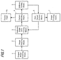
- the copier of this embodiment includes an original image scanning means 1 for scanning the image of an original M placed on an original table 11 (see Figs.2A and 2B and Fig.4) to acquire partial images of data; an image reducing means 2 converting partial images of data captured by original image scanning means 1 into reduced, partial images of data; a reduced partial image data storing means 3 having a plurality of storage areas for storing the reduced partial images of data obtained from image reducing means 2; a pattern matching means 4 for implementing pattern matching based on the overlap image data between the reduced partial images stored in the storage areas in reduced partial image data storing means 3; an address setting means 5 for setting the joining position address that corresponds to the joining position in each storage area of each reduced, partial image of data, based on the processing result obtained from pattern matching means 4; a data output control means 6 which, based on the joining position addresses and the like designated by address setting means 5, outputs the partial images of data from respective storage areas in reduced partial image data storing means 3 in a sequentially, joinable manner
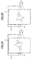
- the copier in this embodiment has an original table 11 which supports an original M and scans the image thereof, at a maximum size of A3, and further has an original table cover 14 which is openable and closable with respect to this original table 11.
- This original table cover 14 is provided with pressing members 13 for holding and fixing the original M placed on original table 11.
- two pressing members 13 are provided so that original M can be held and fixed at its edge along the main scan direction and at its edge along the auxiliary scan direction, but the number, shape, etc. will not be particularly limited and any configuration is applicable as long as original M can be fixed unrotatably.
- Original table 12 has a reference plate 12a for limiting the position of original M with respect to the main scan direction and indicating the position with respect to the auxiliary scan direction.
- This reference plate 12a has a range mark 12b having a predetermined width T at its front end.
- This range mark 12b has a reference indicator 12b1 for designating a single line in the image (overlap image) set within original setting display 12b.
- the aforementioned image outputting means is not illustrated but may be configured of a well-known device, including a laser output means for forming a static latent image on the photoreceptor with image-forming laser beams in accordance with the image data.
- a reference numeral 4a designates a display means producing a display as appropriate in accordance with the processed result from the pattern matching means.
- original image scanning means 1 starts scanning the first partial image M1 of the original, placed over original table 11 (Steps S2 and S3).
- the image data of the first partial image M1 of the original, thus scanned is output from original image scanning means 1 and the partial image of data is converted by image reducing means 7 into reduced partial image of data in accordance with the copy size of the image to be reproduced (Step S4).
- This reduced partial image of data is stored in the first storage area in reduced image data storing means 3. In this way, the first original scan is completed and then the second original scan will be performed.
- Step S6 an unillustrated switch is operated to input the start command of the second scan so as to scan the second partial image M2 of the inverted original M.
- the thus obtained partial image signal by this scan is processed into reduced partial image of data via image reducing means 2, and the resultant data is stored into the second storage area of reduced partial image data storing means 3 (Step S7).
- the partial images of data captured by the first and second scans are of reduced partial image of data, reduced to A4 size.
- matching means 4 starts matching by using the image data representing the common area, from these two images of data stored in the first and second storage areas (Step S8).
- a single matching point is determined first and then a matching line is determined based on this matching point.
- address setting means 5 sets a joining position address of the image data (reference image data) stored in the second storage area of reduced partial image data storing means 3 (Step S9 and S10).
- display panel 4a displays a warning message, as shown in Fig.5, indicating that the operator check the set position of the original and a series of procedures are stopped (Step S15).
- data output control means 6 executes the image data generating operation through Steps S11 to S14.
- Step S11 the partial image of data, captured by the first scan, from the leading line of the first partial image M1 to the matching line, is read out from the first storage area of reduced partial image data storing means 3 to be input to image forming means 7.
- the image forming means based on the input data, reproduces the first partial image M1 on the paper as a recording medium.
- the reduced partial image of data image (the second reduced partial image of data) captured by the second scan is loaded from the second storage area, from the joining position address determined by address setting means 5 to the final line, and this is input to image forming means 7.
- Image forming means 7 then outputs the second reduced partial image M2 onto the paper sequentially after the first reduced partial image M1, thus completing a duplication of the original image reduced to A3 size.
- pressing members 13 for fixing original M over original table 11 since pressing members 13 for fixing original M over original table 11 are provided, it is possible to set up a matching line by determining a single matching point. However, in the case in which no pressing member is provided, two or more matching points may be searched and determined so as to set up a matching line based on the two matching points.
- an original M having a size greater than that of the original table is divided and the divided parts of the original are scanned with the adjoining parts overlapped.
- the image data of the overlap between the partial images is converted into reduced partial image of data corresponding to the copy size, and this reduced partial image of data is used to implement pattern matching so as to compose partial images M thus forming a duplication of the original. Accordingly, this configuration makes it possible to sharply reduce the storage capacity required for the storage means.
- this configuration does not need to compose partial images in the storage means but forms a composed image directly on the recording medium such as paper in accordance with the reduced partial images of data, it is possible to markedly reduce the processing time of image data as compared to the conventional configuration in which the partial images are synthesized first in the storage means and the synthesized image of data is read out. At the same time, this configuration does not need to have a recording means having a large capacity for image composition, thus making it possible to markedly reduce the apparatus' cost.
- original pressing members 13 are provided for fixing the original over the original table so as to prevent the original from being rotated unintentionally, it is possible to effect pattern matching without performing any correction needed stemming from an erroneous rotation of the image and hence further reduce the processing time of image data.
- This embodiment is of a digital copying method and a copier which are embodied based on the above first embodiment.
- this embodiment is configured so as to provide a clear original positioning reference on the original table so that the original image, inclusive of the joining area, can be reliably scanned in parts by multiple scans during the scanning of an original in the basic image joining mode, whereby the original can be set, a multiple number of times, in a simple manner using the image of the joining area as the reference.
- Digital copier 30 is mainly composed of a scanner portion (original image scanning means) 31 and a laser recording portion (image forming means) 32.
- Scanner portion 31 comprises: an original table 35 made up of transparent glass; a reversible automatic document feeder (RADF) 36 for automatically feeding originals to original table 35; and an original image scanning unit (to be referred to hereinbelow as scanner unit) 40 for scanning and reading the image of the original placed on original table 35.
- RDF reversible automatic document feeder
- scanner unit original image scanning unit
- the original image read by this scanner portion 31 is sent in an image data form to an aftermentioned image data input portion, where the image data is subjected to predetermined image processes.
- RADF 36 is a document feeding device which has an unillustrated original tray having a plurality of originals stacked thereon so as to automatically feed the originals thus set, one by one, onto the original table over scanner unit 40.
- RADF 36 further includes: a conveying path for one-sided originals, a conveying path for two-sided originals, conveying path selecting means, sensors for checking and controlling the state of the original passing therethrough; and a controller.
- RADF 36 is well known.
- Scanner unit 40 constituting scanner portion 31 for reading the image of the original on original table 35, includes: a lamp reflector assembly 41 for illuminating the original surface with light; a first scanning unit 40a having a first reflection mirror 42a for reflecting the reflected light from the original toward the photoelectric converting element (CCD); a second scanning unit 40b having second and third reflection mirrors 42b and 42c for leading the reflected light from first reflection mirror 42a to the photoelectric converting element (CCD); an optical lens 43 for focusing the light, reflected from the original and passing through the above reflection mirrors, onto the device (CCD) for converting the image into an electric image signal; and the aforementioned CCD 44 for converting the reflected light image from the original into an electric image signal.
- a lamp reflector assembly 41 for illuminating the original surface with light
- a first scanning unit 40a having a first reflection mirror 42a for reflecting the reflected light from the original toward the photoelectric converting element (CCD)
- a second scanning unit 40b having second and
- Scanner portion 31 is configured so as to move scanner unit 40 along the underside of original table 35 to read the original image while original images are successively fed and discharged by the associated operation of RADF 36 and scanner unit 40.
- the first scanning unit 40a travels at a constant speed V from the left to the right along the original table while the second scanning unit 40b is adapted to travel in the same direction in parallel but at half the speed (V/2) of the speed V.
- V/2 half the speed
- the image data captured by reading the original image through scanner unit 40 is sent to an aftermentioned image processor where the data is subjected to various processes and then the data is temporarily stored into the memory in the image processor.
- the image stored in the memory is read out and transferred to laser recording portion 32 so as to reproduce an image on the recording sheet.
- This laser recording portion 32 comprises a sheet conveying system for conveying sheets as the recording media on which the image is formed, a laser writing unit 46 and an electrophotographic process unit 47 for image forming.
- Laser writing unit 46 includes: a semiconductor laser source for emitting a laser beam in accordance with the image data retrieved from the memory or the image data transferred from an external unit subsequent to inputting scanning image data from the abovementioned scanner unit 40; a polygon mirror for equi-angularly deflecting the laser beam; and an f- ⁇ lens for correcting the equi-angularly deflected laser beam so that the laser spot focused on a photoreceptor drum 48 as an element of electrophotographic processing unit 47 will move at the constant linear velocity across the drum.
- the above electrophotographic process unit 47 includes, as is well known, a charger, a developing unit, a transfer device, a separator, a cleaning device and a charge erasing device, all being disposed around photoreceptor drum 48.
- the sheet conveying system comprises: a conveying portion for conveying paper P to the electrophotographic processing unit for the above-described image formation, in particular to the transfer station where the transfer device is located; paper feed cassettes 51 and 52 for delivering paper P toward the conveying portion; a manual paper feeder 54 for feeding a sheet of paper having a required size as appropriate; a fixing unit 49 for fixing the image, i.e., the toner image, formed on the paper P after the transfer station,; and a re-feeding path 53 for re-feeding the paper P after fixing so as to enable an image to be formed on the rear side thereof.
- a post-processing apparatus 34 which receives paper P with an image recorded thereon and subjects this paper P to predetermined processes.
- laser writing unit 46 irradiates photoreceptor drum 48 with its laser beam in accordance with the image data read out from the image memory so as to form a static latent image over the surface of photoreceptor drum 48.
- the thus formed static latent image is visualized with the toner, then the toner image is electrostatically transferred to the paper fed from any of the multiple paper feeder units 51 or 52, and then fixed thereon through fixing unit 49.
- the paper with an image thus formed thereon is conveyed from fixing unit 49 into post processing unit 34.
- Fig.8 is an overall block diagram showing the control system circuit for controlling various units constituting the digital copier 30 shown in Fig.7 and the image processing portion.
- the control system circuit shown here is configured so that a main central processing unit 401 (CPU) controls the operation of each unit shown in Fig.7 in cooperation with the auxiliary central processing unit (CPU) built into each unit.
- CPU central processing unit
- control system circuit in this embodiment comprises: an operation panel board 100 for management and control of a control panel 103; a machine control board 200 for management and control of the aforementioned units constituting digital copier 30; a CCD board 300 for electrically reading the original image and converting it into electronic data; a main image processing board 400 for subjecting the original image data electronically transformed through CCD board 300 to a predetermined image processes; an auxiliary image processing board 500 for subjecting the image data processed through main image processing board 400 to further predetermined image processes; and extension boards 600 (printer board 601, fax board 603, image joining processing board 602) connected through the interface to auxiliary image processing board 500.
- Operation panel board 100 is basically controlled by auxiliary central processing unit (CPU) 101 and manages the display frame of an LCD display 104 provided on control panel 103, and control input through operation keys 105 for inputting instructions concerning diverse modes and the like.
- CPU central processing unit
- a memory 102 is provided to store various pieces of control information from the control panel, such as data input through operation keys 105, the information to be displayed on the LCD screen.
- auxiliary central processing unit (CPU) 101 exchanges control data with main central processing unit (CPU) 401 to direct the operation of digital copier 30.
- Main central processing unit 401 sends a control signal representing the operation status of digital copier 30 to central processing unit (CPU) 101, so as to drive LCD display portion 104 of control panel 103 to inform the operator of the present status of the digital copier.
- CPU central processing unit
- Machine control board 200 is controlled as a whole by auxiliary central processing unit 202 and manages an automatic document feeder 203 such as ADF, RADF or the like, a scanner driver 204 for driving scanner portion 31 which reads the original image, a process driver 205 for driving electrophotographic process portion 47 for reproducing the image from the image data, a paper conveyer 206 for successively conveying the paper on which an image is recorded, from the paper storage toward electrophotographic process portion 47, a duplex printing unit 207 for inverting the paper with an image recorded thereon so that images can be formed on both sides, a post-processing driver 208 for a post-processing unit 34 for performing post-printing tasks such as stapling of printed sheets with images, and the like.
- an automatic document feeder 203 such as ADF, RADF or the like
- a scanner driver 204 for driving scanner portion 31 which reads the original image
- a process driver 205 for driving electrophotographic process portion 47 for reproducing the image from the image data
- CCD board 300 comprises: a CCD 301 for electrically reading the original image; a CCD gate array (CCD G/A) 302 for driving CCD 301; an analog circuit 303 for performing gain control of the analog data output from CCD 301; an A/D converter 304 for outputting electronic data, that is, for converting the analog output from CCD 301 into the digital signal, and the like.
- the control and management of the CCD board is performed by main central processing unit 401.
- Main image processing board 400 is controlled by main central processing unit 401, so as to reproduce an image with desired graduations based on the electronic data of the original image sent from CCD board 300.
- the main image processing board comprises: a multi-value image processor 402 for directly processing the multi-valued image data, including shading correction, density correction, area separation, filtering, MTF correction, resolution conversion, electronic zooming (magnification transformation), gamma correction and the like; a memory 403 for storing the processed image data and control information including the sequence control program of the processing; and a laser controller 404 for outputting laser driving data to laser writing unit 46 in order to reproduce the image based on the processed image information.
- a multi-value image processor 402 for directly processing the multi-valued image data, including shading correction, density correction, area separation, filtering, MTF correction, resolution conversion, electronic zooming (magnification transformation), gamma correction and the like
- a memory 403 for storing the processed image data and control information including the sequence control program of the processing
- Auxiliary image processing board 500 is connected to main image processing board 400 via connectors 405 and 505 and is adapted to be controlled by main central processing unit 401 on main image processing board 400.
- This auxiliary image processing board comprises: a binary image processor 501; a memory 502 for storing the, image processed, binary image information and the processing control information; a memory gate array (memory G/A) 502a for controlling memory 502; a hard disc (storage means) 503, which stores and manages plural pages of original image data and from which plural pages of original images can be repeatedly loaded a desired number of times so as to produce multiple copies; a RDH gate array (RDH G/A) 503a for controlling hard disc 503; and a SCSI 504a as the external interface; and a SCSI gate array 504 for controlling SCSI 504a.
- RDH G/A RDH gate array
- the aforementioned binary image processor 501 comprises: a processor for converting multi-valued image data into binary image; a processor for rotating the image; a binary zooming processor for zooming the binary image data; a processor for compressing or expanding the image data; and the like.
- Processor 501 also includes a fax interface (FAX I/F) so as to receive and transmit a fax image via commutation means.
- FAX I/F fax interface
- Extension boards 600 include: a printer board 601 which receives the data sent from a personal computer or the like and outputs the print mode data for laser recording portion 32 of digital copier 30; a functional extension board (connection relationship determining means) 602 for adding editing functions such as the image joining process, etc., of the digital copier for enabling efficient use of the features of the digital copier; a facsimile board 603 which enables transmission of the original image captured through the scanner of the digital copier to a remote site and also enables output of image data transmitted from a remote site by way of laser recording portion 32 of the digital copier.
- These extension boards 600 in cooperation with the auxiliary image processing board 500 and main image processing board 400, constitutes the data output control means.
- the originals set at the predetermined position of RADF 36 of digital copier 30 are successively fed, sheet by sheet, onto original table 35 of scanner unit 40. Then the images of the originals are sequentially read by the above described configuration of scanner unit 40 so that scanned 8 bit electronic data is transferred to main image processing board 400.
- the 8 bit electronic data thus transferred to main image processing board 400 is subjected as 8 bit electronic image data to the predetermined processes on multi-value image processor 402.
- the 8 bit electronic image data is subjected to gamma correction and/or other processes and then the output is transferred to laser writing unit (LSU) 46 via laser controller 404.
- LSU laser writing unit
- the original image captured by scanner 31 of digital copier 30 is output from laser recording portion 32 as a copy image with gradations.
- the 8 bit electronic data thus transferred to main image processing board 400 is subjected as 8 bit electronic image data to the predetermined processes on multi-value image processor 402.
- the 8 bit electronic image data is sent through connector 405 on main image processing board 400 and through connector 505 on auxiliary image processing board 500, to auxiliary image processing board 500 in which multi-value-to-binary value converter of binary image processor 501 effects error diffusion and the like while converting the 8 bit electronic image data into 2 bit electronic image data.
- the reason the 8 bit electronic image data is converted into 2 bit electronic image data whilst being subjected to error diffusion and the like, is to reduce the degradation of the image quality since a simple multi-value-to-binary conversion produces problems with the image quality.
- the thus converted 2 bit electronic image data is transferred to disc memory 503 such as a hard disc, keeping every original as one unit, and temporarily stored therein.
- 2 bit electronic image data previously stored temporarily in hard disc 503 is loaded repeatedly the number of times necessarily corresponding to the designated number of prints by the control of the gate array.
- the thus retrieved 2 bit electronic image data is transferred, again via connectors 405 and 505, to main image processing board 400, where the data is subjected to gamma correction and other processes, and is in turn is sent to laser writing unit 46 via laser controller 404.
- the original image captured by scanner 31 of digital copier 30 is output from laser recording portion 32 as a copy image with gradations.
- Image data sent from an external device connected to a network of personal computers is developed on printer board 601 as image data in page units, then is temporarily transferred to auxiliary image processing board 500 via the interface, i.e., SCSI gate array 504 so as to be stored into the memory such as hard disc 503.
- the image developed on printer board 601 as page image data is sent to auxiliary image processing board 500. Upon this data transfer, the page image data is simply stored into hard disc 503 in a temporal manner, without being subjected to binary image processing.
- the fax mode includes: transmission of original images to a remote site and reception of original images from a remote site.
- the original documents to be transmitted are set at the predetermined position of RADF 36 of digital copier 30, and are successively fed sheet by sheet onto original table 35 for scanner unit 40. Then the images of the originals to be transmitted are sequentially read by the above described configuration of scanner unit 40 so that scanned 8 bit electronic data is transferred to main image processing board 400.
- the 8 bit electronic data thus transferred to main image processing board 400 is subjected, as 8 bit electronic image data, to the predetermined processes on multi-value image processor 402.
- the 8 bit electronic image data is sent through connector 405 on main image processing board 400 and through connector 505 on auxiliary image processing board 500, to auxiliary image processing board 500 in which multi-value-to-binary value converter of binary image processor 501 effects error diffusion and the like while converting the 8 bit electronic image data into 2 bit electronic image data.
- the reason the 8 bit electronic image data is converted into 2 bit electronic image data whilst being subjected to error diffusion and other processes, is to reduce the degradation of the image quality since a simple multi-value-to-binary conversion produces problems with the image quality.
- the binarized image data of the originals to be transmitted is compressed in a predetermined format and stored in memory 502.
- the original images to be transmitted which have been compressed in the predetermined format and loaded from memory 502, are transferred to facsimile board 603, where necessary treatments such as modification of the compression format, etc. are effected. Then the thus processed data is sequentially transmitted to the remote site via the commutation line.
- the apparatus executes the predetermined commutation procedure through facsimile board 603 and receives the original image data transmitted from the remote site.
- the received image data which has been compressed in a predetermined format is transferred, via fax interface provided in binary image processor 501 of auxiliary image processing board 500, to binary image processor 501 where the transmitted original image data as page image data is reproduced by means of the compression/expansion processor etc.
- the original image data represented in page units is transferred to main image processing board 400, where it is subjected to gamma correction. Then, based on the thus obtained data, laser controller 404 controls the image writing of LSU 46 so as to reproduce an image.
- the image processing portion effecting predetermined processes on the image information is mainly composed of: a main image processing board 400 for shaping the original image captured by scanner 31 into multi-valued image information; and an auxiliary image processing board 500 which will subject the original image information, which has been shaped in the multi-valued image information through main image processing board 400, to the predetermined processes such as the binarizing process, and which will subject the image information, transferred from a device connected thereto via the external interface, to the predetermined processes, and then transfer the processed data to the multi-value image processor (main image processing board 400) side.
- main image processing board 400 has laser controller 404 for controlling the image data writing of laser writing unit 46.
- the original image input through scanner 31 can be reproduced as a duplicated image by means of laser recording portion 32, without losing the features of the original image as a multi-valued image. Further, when a large amount of originals need to be processed with high-speed using an electronic RDH function or the like, this can be handled by using auxiliary image processing board 500, hard disc 503 and other means.
- the apparatus is adapted to effect appropriate processing of image information in conformity with the digital functional features provided as part of digital copier 30. More specifically, the apparatus has facsimile and printing functions capable of handling the image information from an external device and output it, and especially for the facsimile function, the apparatus is able to, for example, binarize the multi-valued image (retaining the features of the original image) of an original to be transmitted.
- central processing unit (CPU) 401 disposed on main image processing board 400 also manages and controls auxiliary image processing board 500, it is possible to control the total flow of an image to be processed sequentially through the processing sections, and hence it is possible to smoothly handle the data and its processing flow, without losing any image data.
- CPU central processing unit
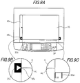
- original table 35 which is made up of a transparent glass plate on which an original is placed, and its periphery.
- the scanning start reference position of original scanner unit 40 in the original scanner 31 is at the left-side edge of the original table 35, and original scanner unit 40 is driven to move toward the right in parallel along the undersurface of original table 35, keeping a constant distance therefrom.
- an original reference positioning plate (to be referred to as a reference plate) 35a for positioning one side of the original to be scanned.
- an original size scale plate 35b which extends in the auxiliary original scan direction.
- a range mark 35c that shows the matching image area, i.e., the image area to be used for the joining process in the original image joining mode is marked at a position in proximity to the control panel OP side of original reference positioning plate 35a.
- Original size scale plate 35b is also marked with scales 35d making clear the size of the original, with respect to the main scan direction of the original, set on original table 35.
- Range mark 35c and each scale 35d are also arranged in a visually manipulative manner arranged so as to make their display clear.
- range mark 35c marked in reference plate 35a makes distinct the original placement range (joining range) to enable acquisition of image data to be used for a joining operation and has a reference indicator 35e to show the center of this range.
- image joining processing board 602 which is connected as a functional extension board.
- pattern matching is performed based on the joining range images, thus determining a matching image in the joining range.
- the multiple partial images temporarily stored in memory 502 or hard disc 503 are connected with one another, using the determined matching image in the joining range, so as to produce a single integrated image from image output portion 32.
- the image extraction, image matching, image joining in the image joining mode can be performed by the image processing operation which will be described in detail later.
- Figs.10A and 10B illustrate the state of an original m which is greater than the size of the original table 35 and placed over original table 35 of digital copier 30, and the operational steps of storing the captured original image data as partial images of data to be joined.
- Figs.10A and 10B show the procedural flow of separately reading the upper half partial image (the first partial image) m1 of the original set on original table 35, and the lower half partial image (the second partial image) m2 of the original and the operation of preparation for the image joining process for multiple partial images m1 and m2 of data.
- the first partial image m1 of original m is scanned by scanner 31 of digital copier 30.
- range mark 35c indicating the joining range for the joining process is provided in proximity to the control panel OP side on reference plate 35a provided on the reference side of original table 35, the original is set so that the area to be joined of the first partial image m1 resides within the range of this range mark 35c.
- the data from the first partial image m1 of original m, scanned and captured by scanner 31 is handled as multi-valued image data on main image processing board 400 and subjected to the predetermined processes. Resultantly, the data is shaped into a 70% reduced, multi-valued image of data so that an A2 original may be handled as an A3 image.
- the multi-valued data of the image section residing at range mark 35c (the first matching image to be joined, designated at m12) is used to produce reference data D1 for pattern matching.
- the 70% reduced, multi-valued image of data undergoes multi-value-to-binary value conversion on auxiliary image processing board 500, and thereafter the resultant data is separated into the first image to be joined m11 and the first matching image to be joined m12.
- the data of the first image to be joined m11 is turned 90° while the data of the first matching image to be joined m12 and reference data D1 for matching are turned 180°.
- the prepared data of the first image to be joined m11, the first matching image to be joined m12 and reference data D1 are temporarily stored for later use into memory 502 capable of temporary storage.
- the original is turned 180° or placed upside down, and the second partial image m2 of original m is read by image scanner portion 31 of digital copier 30.
- the original is set so that the area to be joined of the second partial image m2 resides within the range of this range mark 35c, which is provided in proximity to the control panel OP side on reference plate 35a provided on the reference side of original table 35, indicating the joining range for the joining process.
- the data from the second partial image, scanned and captured by scanner 31 is handled as multi-valued data on main image processing board 400 and subjected to the predetermined processes. Resultantly, the data is shaped into 70% reduced, multi-valued image of data so that an A2 original may be handled as an A3 image.
- the multi-valued data of the image section residing at range mark 35c (the second matching image to be joined, designated at m22) is used to produce reference data D2 for pattern matching.
- the 70% reduced multi-valued image of data undergoes multi-value-to-binary value conversion on auxiliary image processing board 500, and thereafter the resultant data is separated into the second image to be joined m21 and the second matching image to be joined m22.
- the prepared data of the second image to be joined m21, the second matching image to be joined m22 and reference data D2 are temporarily stored for later use into memory 502 capable of temporary storage.
- the original to be the target of the joining process may be folded in two, or a pair of marks may be added at the opposing positions in both sides of the original, so that the fold or the marks can be set at the reference indicator 35e provided in the middle of joining range mark 35c, marked on original reference positioning plate 35a in proximity to the control panel OP side.
- the reference indicator 35e provided in the middle of joining range mark 35c, marked on original reference positioning plate 35a in proximity to the control panel OP side.
- the unnecessary rear end parts m12a and m22a, which were captured when each partial image was placed on original table 35 are removed based on the original width information, respectively from the data of first matching image to be joined m12 with reference data D1 and from the data of second matching image to be joined m22 with reference data D2.
- pattern matching is implemented based on reference image data D1 and D2 so as to produce a connection image m30 of the original center, which is composited of the data of the first matching image to be joined m12 and the data of the second matching image to be joined m22.
- Connection image m30 thus prepared is again transferred to auxiliary image processing board 500, where the image m30 is turned 270° so that its orientation coincides with that of the first image to be joined m11 and the second image to be joined m21, and then temporarily stored in memory 502.
- the data stored in memory 502 is loaded therefrom sequentially in the order of the data of the first image to be joined m11 and the data of connection image m30, and then the data of the second image to be joined m21, and is transferred to main image processing board 400, where the data is subjected to gamma correction and then is supplied to laser controller 404 so that LSU (laser scanning unit) 46 writes an image on electrophotographic photoreceptor 48.
- LSU laser scanning unit
- the data stored in memory 502 i.e., the data of the first image to be joined m11, connection image m30 and the second image to be joined m21 may be integrated so as to complete the data of the final image ma and store it.
- the complete data may be loaded sequentially from memory 502 and transferred to main image processing board 400, where the data is subjected to gamma correction and then is supplied to laser controller 404 so that LSU (laser scanning unit) 46 writes an image on electrophotographic photoreceptor 48.
- LSU laser scanning unit
- the image joining mode has been explained in which an original image is read part by part by multiple scans and the partial images are used to reproduce a reduced integrated image.
- a display image P1 shown in Fig.12 is displayed on the LCD dot-matrix display portion P in control panel OP so as to allow for the operator to input the original width.
- a transparent touch-panel tablet so as to be able to accept the input commands which are selected by the operator's touching desired keys in the key display portion P2 whilst viewing the display contents.
- the original width presently selected is displayed in numeral in the approximately center of the display frame, with up-key P21 and down-key P22 disposed below for increasing or decreasing the setting in steps of the predetermined unit.
- Displayed further on the right side of the display frame are four registration keys P23, P24, P25 and P26, for which frequently used original widths can be selected and stored beforehand so that the operator can directly input the original width with a simple touch.
- the scanning range of reading the original is determined in accordance with the input original width information and thereby the extraction range of the matching image to be used for the joining process of captured, target images to be joined can also be limited, so that the speed of the matching processing in image joining processing board 602 can be improved and hence the matching process can be completed in a shorter time.
- the operator can check scales 35d and determine the numerical value of a scale 35d close to which the edge of the original resides, and hence can easily set the original width by operating the touch panel of key display portion P2 in display frame P1 shown in Fig.12.
- the sheet sizes include, in addition to A3 size, B4, A4, B5 etc. Therefore, in the case where an A4 sized or B5 sized sheet is used, it is necessary to consider that the duplication may be performed with the sheet's orientation rotated 90° (in A4R and B5R modes).
- the above embodiment is configured so that the first step of the image joining process will be implemented, at a zoom ratio of 70% when an A2 sized original is reproduced on an A3 sized printed sheet.
- the joined image of A3 size is zoomed or adjusted in size so that the joined image will fit a selected size of sheet, thus making it possible to output the image on the selected size of sheet. More specifically, the joined image of A3 size is adjusted to a selected size of sheet, such as being reduced to 86% for B4, 70% for A4, 61% for B5.
- the original is processed based on the operation described above with reference to Figs.10A, 10B and 11, then the A3 sized joined image may be simply reduced by the respective ratio for B4, A4R and B5R paper.
- the output print is of A4 or B5 format
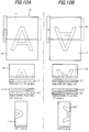
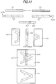
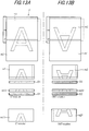
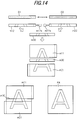
- the partial images of an original obtained part by part by multiple scans specifically, the first image to be joined m11, the second image to be joined m12, the first matching image to be joined m21 and the second matching image to be joined m22, need to be rotated as required, as shown in Figs.13A, 13B and 14.
- a single A3 image is reproduced, which, in turn, is shaped into the image of A4 or B5 format.
- range mark 35c has a reference indicator 35e in the center thereof, but reference indicator 35e does not need to be positioned necessarily in the center and may be located at other positions as long as it is provided within range mark 35c. Further, sub-indicators other than reference indicator 35e may be provided within the range mark. Thus, the present invention will not be limited to the above embodied modes.
- an original greater than the size the original table can handle is divided into parts and the thus divided parts of the original are scanned in a manner that produces at least an overlapping area between adjoining partial images.
- the image data containing the overlap area between partial images is converted into reduced partial images of data in correspondence with the size of duplication.
- These reduced partial images of data are used to implement pattern matching so as to composite separated, reduced partial images of the original into an integrated, duplicated image. Therefore, it is possible to markedly reduce the storage capacity required for the storage means.
- the composted image is formed directly on the recording medium such as paper etc., in accordance with sequential, partial images of data, it is possible to remarkably shorten the processing time of image data, compared to the conventional configuration in which partial images are first synthesized in the storage means and the synthesized image data is loaded therefrom. Further, since this configuration eliminates the necessity of a high capacity storage means for image composition, the apparatus' cost can be sharply reduced.
- the reference plate located at the reference position on the original table is provided with a range mark displaying the joining area for matching and a reference indicator within this range mark. Therefore, when the image of an original is read, part by part, by multiple scans, it is possible to reliably capture the overlap area of the image, which corresponds to the joining portion of the original and hence is required for pattern matching. As a result, it is possible to easily deal with various types of originals including originals of an irregular size and shape. Further, the pre-process for detecting the position of the original image area is no longer necessary, so that it is possible to sharply increase the speed of the imaging process.
- a pair of marks added at the opposing positions on both sides of the original or a fold of the original can be set in alignment with the reference indicator provided within the range mark displaying the pattern matching area, so that it is possible to more reliably capture the image of the area required for joining the partial images of the original.
- the original is set so that a pair of marks added at the opposing positions on both sides of the original, or a fold of the original is in alignment with the reference indicator, it is possible to reliably capture the partial images whilst suppressing the area required for image joining to the minimum. As a result, it is possible to further reduce the processing time and the processing accuracy.
Landscapes
- Engineering & Computer Science (AREA)
- Multimedia (AREA)
- Signal Processing (AREA)
- Editing Of Facsimile Originals (AREA)
- Image Processing (AREA)
- Storing Facsimile Image Data (AREA)
- Image Analysis (AREA)
- Control Or Security For Electrophotography (AREA)
- Processing Or Creating Images (AREA)
Applications Claiming Priority (2)
| Application Number | Priority Date | Filing Date | Title |
|---|---|---|---|
| JP36031397A JP3435043B2 (ja) | 1997-12-26 | 1997-12-26 | 画像形成装置 |
| JP36031397 | 1997-12-26 |
Publications (3)
| Publication Number | Publication Date |
|---|---|
| EP0926882A2 true EP0926882A2 (de) | 1999-06-30 |
| EP0926882A3 EP0926882A3 (de) | 2002-08-21 |
| EP0926882B1 EP0926882B1 (de) | 2006-11-22 |
Family
ID=18468865
Family Applications (1)
| Application Number | Title | Priority Date | Filing Date |
|---|---|---|---|
| EP98123759A Expired - Lifetime EP0926882B1 (de) | 1997-12-26 | 1998-12-14 | Bilderzeugungsvorrichtung und -verfahren |
Country Status (4)
| Country | Link |
|---|---|
| US (1) | US6690482B1 (de) |
| EP (1) | EP0926882B1 (de) |
| JP (1) | JP3435043B2 (de) |
| DE (1) | DE69836467T2 (de) |
Cited By (4)
| Publication number | Priority date | Publication date | Assignee | Title |
|---|---|---|---|---|
| EP1253773A3 (de) * | 2001-04-25 | 2005-05-11 | Seiko Epson Corporation | Divisionaldruckkontrolle |
| EP1667424A3 (de) * | 2001-04-25 | 2007-10-03 | Seiko Epson Corporation | Divisionaldruckkontrolle |
| WO2014082639A3 (de) * | 2012-11-28 | 2014-08-14 | Wolfgang Baum | VERFAHREN UND VORRICHTUNG ZUM EINLESEN UND AUSGEBEN VON ÜBERGROßEN DOKUMENTEN |
| CN108876691A (zh) * | 2017-05-10 | 2018-11-23 | 北京大学 | 自适应可逆水印方法及系统 |
Families Citing this family (22)
| Publication number | Priority date | Publication date | Assignee | Title |
|---|---|---|---|---|
| EP1091560A1 (de) * | 1999-10-05 | 2001-04-11 | Hewlett-Packard Company | Verfahren und Gerät zum Abtasten von Übergrössendokumenten |
| JP2002218180A (ja) * | 2001-01-23 | 2002-08-02 | Ricoh Co Ltd | ファクシミリ装置及びその制御方法 |
| US7136199B2 (en) * | 2001-10-26 | 2006-11-14 | Hewlett-Packard Development Company, Lp. | Document scanning apparatus with oversize document handling capability |
| US7248753B2 (en) * | 2003-07-31 | 2007-07-24 | Kyocera Mita Corporation | Image displaying apparatus and program product for displaying image |
| JP2005124063A (ja) * | 2003-10-20 | 2005-05-12 | Sharp Corp | 画像形成装置 |
| US7733539B2 (en) * | 2005-03-16 | 2010-06-08 | Lexmark International, Inc. | Scanning method for stitching images |
| JP2009506339A (ja) * | 2005-08-30 | 2009-02-12 | カムテック エルティーディー. | 検査システム、及び基準フレームに基づいて欠陥を検査する方法 |
| US7742659B2 (en) * | 2006-05-09 | 2010-06-22 | Arcsoft, Inc. | Edge based auto order supporting rotation algorithm |
| US7627191B2 (en) * | 2006-08-14 | 2009-12-01 | Xerox Corporation | Image manipulation |
| DE102009005292A1 (de) | 2008-02-11 | 2009-08-13 | Heidelberger Druckmaschinen Ag | Messvorrichtung zur teilweisen Erfassung bogenförmiger Bedruckstoffe |
| JP2009239688A (ja) * | 2008-03-27 | 2009-10-15 | Nec Access Technica Ltd | 画像合成装置 |
| JP4597224B2 (ja) * | 2008-06-25 | 2010-12-15 | シャープ株式会社 | 画像形成装置および画像形成方法 |
| US8520273B2 (en) * | 2009-05-19 | 2013-08-27 | Sindoh Co., Ltd. | A4-size scanner having function of scanning A3 document and scanning method thereof |
| CN101895661B (zh) * | 2010-01-11 | 2016-01-27 | 珠海天威飞马打印耗材有限公司 | 耗材芯片、耗材容器、成像装置及其成像控制方法 |
| JP2011210088A (ja) * | 2010-03-30 | 2011-10-20 | Brother Industries Ltd | 印刷制御装置、プログラム、印刷装置、及び印刷制御システム |
| US8717641B2 (en) * | 2011-07-13 | 2014-05-06 | Hewlett-Packard Development Company, L.P. | System and method for edge identification to position components of a scanner |
| US8699098B2 (en) * | 2011-07-13 | 2014-04-15 | Hewlett-Packard Development Company, L.P. | Scanner gear assembly |
| JP5929128B2 (ja) * | 2011-11-29 | 2016-06-01 | ブラザー工業株式会社 | 印刷装置 |
| JP5492233B2 (ja) * | 2012-02-07 | 2014-05-14 | 富士フイルム株式会社 | 画像評価装置、画像評価方法及びプログラム |
| US9013761B2 (en) | 2013-04-16 | 2015-04-21 | Hewlett-Packard Development Company, L.P. | Scanner with a scan sensor having a width smaller than the platen |
| JP6409460B2 (ja) * | 2014-09-30 | 2018-10-24 | ブラザー工業株式会社 | 画像処理装置、および、コンピュータプログラム |
| JP7318387B2 (ja) * | 2019-07-24 | 2023-08-01 | 富士フイルムビジネスイノベーション株式会社 | 画像処理装置、情報処理プログラム |
Family Cites Families (8)
| Publication number | Priority date | Publication date | Assignee | Title |
|---|---|---|---|---|
| JPS61265964A (ja) | 1985-05-20 | 1986-11-25 | Toshiba Corp | デイジタル画像形成装置 |
| US5033102A (en) | 1988-01-29 | 1991-07-16 | Minolta Camera Kabushiki Kaisha | Image reading apparatus capable of reading desired image areas |
| US5465103A (en) | 1989-08-28 | 1995-11-07 | Mitsubishi Denki Kabushiki Kaisha | Display device with coordinate input function |
| JP2917155B2 (ja) | 1989-12-18 | 1999-07-12 | 株式会社日立製作所 | 画像結合装置及び方法 |
| US5465163A (en) * | 1991-03-18 | 1995-11-07 | Canon Kabushiki Kaisha | Image processing method and apparatus for processing oversized original images and for synthesizing multiple images |
| JP3183691B2 (ja) | 1991-11-19 | 2001-07-09 | 株式会社リコー | 画像合成装置 |
| JPH07131631A (ja) | 1993-11-01 | 1995-05-19 | Fuji Xerox Co Ltd | デジタル複写方法及びデジタル複写機 |
| US6148118A (en) * | 1995-07-05 | 2000-11-14 | Minolta Co., Ltd. | Image processing apparatus capable of reproducing large-sized document |
-
1997
- 1997-12-26 JP JP36031397A patent/JP3435043B2/ja not_active Expired - Fee Related
-
1998
- 1998-11-30 US US09/200,795 patent/US6690482B1/en not_active Expired - Lifetime
- 1998-12-14 DE DE69836467T patent/DE69836467T2/de not_active Expired - Lifetime
- 1998-12-14 EP EP98123759A patent/EP0926882B1/de not_active Expired - Lifetime
Cited By (6)
| Publication number | Priority date | Publication date | Assignee | Title |
|---|---|---|---|---|
| EP1253773A3 (de) * | 2001-04-25 | 2005-05-11 | Seiko Epson Corporation | Divisionaldruckkontrolle |
| EP1667424A3 (de) * | 2001-04-25 | 2007-10-03 | Seiko Epson Corporation | Divisionaldruckkontrolle |
| US7551310B2 (en) | 2001-04-25 | 2009-06-23 | Seiko Epson Corporation | Divisional print control |
| US8395808B2 (en) | 2001-04-25 | 2013-03-12 | Seiko Epson Corporation | Divisional print control |
| WO2014082639A3 (de) * | 2012-11-28 | 2014-08-14 | Wolfgang Baum | VERFAHREN UND VORRICHTUNG ZUM EINLESEN UND AUSGEBEN VON ÜBERGROßEN DOKUMENTEN |
| CN108876691A (zh) * | 2017-05-10 | 2018-11-23 | 北京大学 | 自适应可逆水印方法及系统 |
Also Published As
| Publication number | Publication date |
|---|---|
| DE69836467D1 (de) | 2007-01-04 |
| DE69836467T2 (de) | 2007-09-13 |
| US6690482B1 (en) | 2004-02-10 |
| EP0926882A3 (de) | 2002-08-21 |
| EP0926882B1 (de) | 2006-11-22 |
| JPH11196256A (ja) | 1999-07-21 |
| JP3435043B2 (ja) | 2003-08-11 |
Similar Documents
| Publication | Publication Date | Title |
|---|---|---|
| EP0926882B1 (de) | Bilderzeugungsvorrichtung und -verfahren | |
| JP3630705B2 (ja) | デジタル複写装置 | |
| JP3432736B2 (ja) | 画像処理装置 | |
| EP0476964B1 (de) | Verfahren und Vorrichtung zum Abtasten eines gekennzeichneten Dokuments | |
| JPH0758942A (ja) | 電子複写印刷システム | |
| US20100123940A1 (en) | Image forming apparatus and image forming method | |
| US5224181A (en) | Image processor | |
| JP3720502B2 (ja) | 画像処理装置及び該装置における画像処理方法、並びにコンピュータ読み取り可能な記憶媒体 | |
| US6304681B1 (en) | Image processing apparatus for executing image processing in correspondence with portrait and landscape types | |
| US6178273B1 (en) | Image forming apparatus for storing document image in memory by one document feeding operation and the method thereof | |
| JPH08248818A (ja) | 画像オーバレイモードにおいてフレキシブルな原書類入力走査を行う複写装置および複写方法 | |
| JP2002185767A (ja) | 画像処理装置及び方法 | |
| JP3997680B2 (ja) | 画像形成装置 | |
| JPH11305609A (ja) | 試しコピー機能付画像形成装置 | |
| JPH1013587A (ja) | 画像形成装置 | |
| JP4076827B2 (ja) | 画像形成装置 | |
| JP4104275B2 (ja) | 画像形成装置 | |
| JP3978400B2 (ja) | 画像形成装置 | |
| JP2005062893A (ja) | 画像形成装置及び画像形成方法 | |
| JP3834219B2 (ja) | 画像形成装置及び画像形成方法 | |
| JP3206934B2 (ja) | 両面複写装置 | |
| JPH07245695A (ja) | デジタル複写機 | |
| JP2005051382A (ja) | 画像形成装置 | |
| JPH0774920A (ja) | 画像形成装置 | |
| JPH09247425A (ja) | 画像形成装置 |
Legal Events
| Date | Code | Title | Description |
|---|---|---|---|
| PUAI | Public reference made under article 153(3) epc to a published international application that has entered the european phase |
Free format text: ORIGINAL CODE: 0009012 |
|
| AK | Designated contracting states |
Kind code of ref document: A2 Designated state(s): AT BE CH CY DE DK ES FI FR GB GR IE IT LI LU MC NL PT SE |
|
| AX | Request for extension of the european patent |
Free format text: AL;LT;LV;MK;RO;SI |
|
| PUAL | Search report despatched |
Free format text: ORIGINAL CODE: 0009013 |
|
| AK | Designated contracting states |
Kind code of ref document: A3 Designated state(s): AT BE CH CY DE DK ES FI FR GB GR IE IT LI LU MC NL PT SE |
|
| AX | Request for extension of the european patent |
Free format text: AL;LT;LV;MK;RO;SI |
|
| 16A | New documents despatched to applicant after publication of the search report |
Effective date: 20021119 |
|
| 17P | Request for examination filed |
Effective date: 20030116 |
|
| AKX | Designation fees paid |
Designated state(s): DE FR GB |
|
| 17Q | First examination report despatched |
Effective date: 20050427 |
|
| GRAP | Despatch of communication of intention to grant a patent |
Free format text: ORIGINAL CODE: EPIDOSNIGR1 |
|
| GRAS | Grant fee paid |
Free format text: ORIGINAL CODE: EPIDOSNIGR3 |
|
| GRAA | (expected) grant |
Free format text: ORIGINAL CODE: 0009210 |
|
| AK | Designated contracting states |
Kind code of ref document: B1 Designated state(s): DE FR GB |
|
| REG | Reference to a national code |
Ref country code: GB Ref legal event code: FG4D |
|
| REF | Corresponds to: |
Ref document number: 69836467 Country of ref document: DE Date of ref document: 20070104 Kind code of ref document: P |
|
| ET | Fr: translation filed | ||
| PLBE | No opposition filed within time limit |
Free format text: ORIGINAL CODE: 0009261 |
|
| STAA | Information on the status of an ep patent application or granted ep patent |
Free format text: STATUS: NO OPPOSITION FILED WITHIN TIME LIMIT |
|
| 26N | No opposition filed |
Effective date: 20070823 |
|
| REG | Reference to a national code |
Ref country code: FR Ref legal event code: PLFP Year of fee payment: 18 |
|
| REG | Reference to a national code |
Ref country code: FR Ref legal event code: PLFP Year of fee payment: 19 |
|
| PGFP | Annual fee paid to national office [announced via postgrant information from national office to epo] |
Ref country code: GB Payment date: 20161222 Year of fee payment: 19 Ref country code: DE Payment date: 20161213 Year of fee payment: 19 |
|
| PGFP | Annual fee paid to national office [announced via postgrant information from national office to epo] |
Ref country code: FR Payment date: 20161222 Year of fee payment: 19 |
|
| REG | Reference to a national code |
Ref country code: DE Ref legal event code: R119 Ref document number: 69836467 Country of ref document: DE |
|
| GBPC | Gb: european patent ceased through non-payment of renewal fee |
Effective date: 20171214 |
|
| REG | Reference to a national code |
Ref country code: FR Ref legal event code: ST Effective date: 20180831 |
|
| PG25 | Lapsed in a contracting state [announced via postgrant information from national office to epo] |
Ref country code: DE Free format text: LAPSE BECAUSE OF NON-PAYMENT OF DUE FEES Effective date: 20180703 Ref country code: FR Free format text: LAPSE BECAUSE OF NON-PAYMENT OF DUE FEES Effective date: 20180102 |
|
| PG25 | Lapsed in a contracting state [announced via postgrant information from national office to epo] |
Ref country code: GB Free format text: LAPSE BECAUSE OF NON-PAYMENT OF DUE FEES Effective date: 20171214 |