EP0926938B1 - Gestell für Fernmeldeapparatur - Google Patents
Gestell für Fernmeldeapparatur Download PDFInfo
- Publication number
- EP0926938B1 EP0926938B1 EP98310095A EP98310095A EP0926938B1 EP 0926938 B1 EP0926938 B1 EP 0926938B1 EP 98310095 A EP98310095 A EP 98310095A EP 98310095 A EP98310095 A EP 98310095A EP 0926938 B1 EP0926938 B1 EP 0926938B1
- Authority
- EP
- European Patent Office
- Prior art keywords
- base
- telecommunications rack
- substantially vertical
- rack
- members
- Prior art date
- Legal status (The legal status is an assumption and is not a legal conclusion. Google has not performed a legal analysis and makes no representation as to the accuracy of the status listed.)
- Expired - Lifetime
Links
Images



Classifications
-
- H—ELECTRICITY
- H04—ELECTRIC COMMUNICATION TECHNIQUE
- H04Q—SELECTING
- H04Q1/00—Details of selecting apparatus or arrangements
- H04Q1/02—Constructional details
- H04Q1/11—Protection against environment
- H04Q1/112—Protection against environment mechanical protection, e.g. resistance to earthquakes
-
- H—ELECTRICITY
- H04—ELECTRIC COMMUNICATION TECHNIQUE
- H04Q—SELECTING
- H04Q1/00—Details of selecting apparatus or arrangements
- H04Q1/02—Constructional details
- H04Q1/09—Frames or mounting racks not otherwise provided for
-
- H—ELECTRICITY
- H05—ELECTRIC TECHNIQUES NOT OTHERWISE PROVIDED FOR
- H05K—PRINTED CIRCUITS; CASINGS OR CONSTRUCTIONAL DETAILS OF ELECTRIC APPARATUS; MANUFACTURE OF ASSEMBLAGES OF ELECTRICAL COMPONENTS
- H05K7/00—Constructional details common to different types of electric apparatus
- H05K7/18—Construction of rack or frame
- H05K7/186—Construction of rack or frame for supporting telecommunication equipment
Definitions
- the present invention relates to a rack for supporting equipment and is particularly concerned with a rack for supporting telecommunications equipment, see e.g. US-A-5004107.
- Telecommunications racks are used to support telecommunications equipment on floors of office buildings that are designed to bear these loads. These racks also permit cables to be installed and maintained while the equipment is in place.
- NEBS N etwork E quipment B uilding S ystem
- ETSI E uropean T elecommunications S tandards I nstitute
- the design criteria stipulate, among other things, the maximum deflection of the top of the rack under seismic loading conditions. To meet these criteria, the rack should be relatively stiff.
- One difficulty with these designs is that racks gain weight in order to meet this stiffness requirement.
- the effect of this increased stiffness is that the natural frequency of the rack, which is calculated by dividing the stiffness of the rack by its weight, is reduced.
- a low value of natural frequency is a disadvantage since this increases the likelihood of catastrophic failure under seismic loading conditions.
- Telecommunications racks are typically constructed with members which are made of various alloys of aluminum or steel. Various techniques are used to make these members, such as roll forming or extrusion, and the members are either welded or bolted together. The members of these racks typically have flat and solid surfaces, which do not allow cables to pass through the members. Creating openings in these members for cabling is undesirable since the openings will weaken or reduce the stiffness of the rack.
- An object of the present invention is to provide an improved telecommunications rack, in which these disadvantages are obviated or mitigated.
- a telecommunications rack made of structural steel, comprising a base, a top, two spaced substantially upright supports extending between and secured to the base and the top, each support having a plurality of spaced substantially vertical members, and a truss member disposed between at least two of the substantially vertical members and secured thereto.
- a telecommunications rack made of structural steel and comprising a base, a top and two open-structure sides extending between the base and the top, wherein each side comprises two spaced substantially vertical members extending between and secured to the base and the top, and an elongate truss member having a generally zig-zag configuration defining spaced crests, the truss member being located between the two spaced members, with its crests welded to the two spaced members, and extending between the base and the top.
- the invention provides improved structural stiffness with a lightweight rack and improved access to the equipment for cabling.
- the rack design is also suitable for manufacturing to either ETSI or NEBS standards.
- a rectangular telecommunications rack according to an embodiment of the invention is generally indicated by 10 and consists of upright supports 20 and 30, a base 40 and a top 50.
- the top 50 has two opposite ends, 52 and 54, which are each attached to upright supports 20 and 30 by welds, bolts or other fasteners.
- the top 50 has a generally rectangular surface 56 extending between the opposite ends 52 and 54.
- the surface 56 contains many openings 58, preferably in a slit shape, to permit air flow from the telecommunications equipment and to allow cable troughs (not shown) to be mounted, usually with bolts, to surface 56. Cable troughs are devices, typically made of steel, that are located above the racks and permit cabling to be connected from one bay of equipment to another.
- the surface 56 also has holes 59 with weld nuts (not shown) mounted to the interior of surface 56.
- weld nuts are known nuts, hexagonal in shape, that are welded to the interior of surface 56. As a result of attaching weld nuts to the interior of surface 56, additional threads are available to attach supports for the cable troughs overhead. Alternatively, weld nuts permit the attachment of lifting hooks to surface 56. Lifting hooks, which are not shown, allow cables to be attached to the rack, which may be loaded with telecommunications equipment, to raise and manoeuvre the rack into position.
- the top 50 is made of sheet steel that is 3 mm thick, and holes 59 are 13.5 mm in diameter.
- Upright supports 20 and 30 each consist of two formed sheet steel members, 60 and 70, at the rear and front, respectively, with a cross member 80 joining rear member 60 to front member 70.
- rear member 60 and front member 70 are constructed with channel shaped sheet steel, and preferably, cross member 80 is made from formed wire which is approximately 12.7 mm in diameter.
- rear member 60 consists of two members, 62 and 64, each of which is C-shaped in cross-section. Members 62 and 64 oppose one another, and member 64 is sized to fit within member 62 to form a rectangular section.
- This design creates a lightweight structure with a high torsional stiffness and consequently a high natural frequency.
- the high natural frequency is advantageous in locations that are susceptible to seismic occurrences in order to maintain the integrity of the telecommunications equipment.
- rear members 60 are stiffer than front members 70, during a seismic occurrence, for example, rear members 60 bear most of the dynamic load.
- Member 64 comprises section 66 which faces the front of the rack, and two opposing side sections 63.
- Side sections 63 have a shorter depth than side sections 65 of the C-shaped member 62. Accordingly, as illustrated in Fig. 3, when the member 64 fits against the member 62, a free end portion 67 of each side section 65 extends beyond section 66.
- the resultant groove that is formed between portion 67 of one of the side sections 65 and section 66 permits welding opposing members 62 and 64 together, and also permits welding cross member 80 to member 60.
- the side section 65 which is not welded to cross member 80 is approximately the same depth as side sections 63, thus eliminating portion 67 in these lengths.
- junctioning plate (not shown) can be attached with bolts to section 66 and the junctioning plate will be flush against section 66 without interference from portion 67.
- a junctioning plate is a plate with holes that joins adjacent racks in a side-by-side configuration. In such an arrangement, the side sections 65 on the outside of the racks face one another.
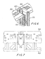
- Figs. 6 and 7 illustrate a side-by-side configuration.
- Member 70 is S-shaped in cross-section and positioned opposite member 60, such that one section of the S-section, shown in Fig. 3 as section 71, faces section 66 of member 64.
- Section 71 has various "cut-away" sections 75 which are preferably 80 mm long. At these locations, a sufficient gap exists in section 71 to accommodate cross member 80, described in detail below.
- Section 72 is another section of S-shaped member 70 that extends parallel to section 71 but is offset from section 71 and is seen when the rack is viewed from the front.
- Section 73 is another section of S-shaped member 70 that extends at a right angle to section 72 and is located between sections 72 and 71.
- Sections 72 and 73 have many holes 92 throughout their lengths, which in a preferred embodiment are 5.5 mm in diameter. Holes 92 are spaced approximately 25 mm apart on section 72, and are used for mounting the shelves, which contain the telecommunications equipment, to the rack. Thread forming screws are used to attach the shelves to the rack.
- holes 92 are approximately 100 mm apart except in the region near the bottom and top. In these regions, from approximately 120 mm from the bottom and the top of section 73, the spacing between holes 92 is approximately 25 mm. On section 73, the holes 92 are used to attach accessories to the rack. Holes 92 have a closer spacing near the top and bottom since most accessories are installed in these regions. If an accessory needs to the installed at a certain location along the rest of section 73, the 100 mm spacing permits one to easily count the number of holes to ensure the accessory is mounted to both members 70 at the same location. Accessories are mounted with thread forming screws.
- the width between rear members 60 at the rear of the rack is greater than the width between front members 70 at the front of the rack.
- Figs. 6 and 7 where two racks are shown in a side-by-side configuration.
- cabling may be attached to cross member 80 and there is adequate space for the cabling since a slot is created between adjacent front members 70 that extends to the rear of the rack.
- Member 64 has many holes 90 throughout its length and located in section 66, which are clearance holes used to gain access to smaller diameter holes (not shown) in the rear of member 60. These holes at the rear of member 60 are used to bolt racks together in a back-to-back configuration.
- a rack may have a shear plate (not shown) attached to members 60.
- a shear plate is a solid steel plate which will close in the rear of the rack and provide further stiffness to the rack.
- holes 90 are 21 mm in diameter, and the smaller diameter holes are 9 mm.
- member 64 also has smaller holes 94 at either end of section 66, which are used for side to side junctioning of racks.
- the junctioning plate, described above, is attached to the rear member 60 through holes 94.
- holes 94 are, 5.5 mm in diameter.
- Member 62 contains three holes 93, one at either end and one in the middle of side sections 63, which are tooling holes used by the manufacturer to align members 62 and 63 during welding.
- Member 62 also contains two holes 95 located approximately 70 mm from the top and bottom which may be used to attach accessories such as side panels or end of aisle panels. In a preferred embodiment, holes 95 are 5.5 mm in diameter.
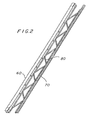
- cross member 80 is made of formed wire and is welded to members 60 and 70 at a plurality of locations. Formed wire is attached at either end of member 60 by welding one end of wire 80 to section 66 and the portion 67 of side section 65 that extends beyond section 66. This configuration is shown in Fig. 3.
- Cross member 80 extends along members 60 and 70 in a wave shaped or "zig-zag" pattern, such that cross member 80 is welded along the structure 60 at locations that are generally between the locations where it is welded along the structure 70.
- This welding pattern with members 60, 70 and cross member 80 creates a truss-like shape with cross member 80 forming crests at the locations where it is welded to members 60 and 70.
- the crests are welded to the S-shaped member 70 at locations 75 where section 71 is "cut-away” and alternate crests are welded to the member 60 along the portion 67 of side section 65 that extends beyond section 66.
- cross member 80 is shown to extend in a wave pattern, it is understood that cross member 80 could also consist of generally straight sections that extend along members 60 and 70 in a "zig-zag" fashion.
- cross member 80 is welded to members 60 and 70 such that an angle of between 30 and 60 degrees exists between cross member 80 and the vertical members, which are either rear members 60 or front members 70 at the point where cross member 80 is welded to the vertical members, either 60 or 70.
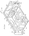
- the base 40 is a sheet metal structure with sides 42 and 44, which are opposite and parallel to each other, a rear wall 46 and a front wall 47, which are also opposite and parallel to each other.
- a bottom 48 is attached at the lower edges of walls 46 and 47 and sides 42 and 44.
- the walls 46 and 47, sides 42 and 44, and bottom 48 of the base 40 are sheet metal with open areas, and connected to each other with welds.
- Rear and front walls 46 and 47 and bottom 48 are made from the same sheet of metal. These open areas, as illustrated by opening 43, allow weight to be removed from the base while maintaining its strength capability and they also permit airflow and cable passage in the base.
- the base 40 is mounted to the floor with bolts 100, shown in Fig. 5, or anchors which pass through four oblong slots 49 in the bottom and located respectively proximate the four comers of the base. Slots 49 permit positioning of bolts 100 to avoid reinforcement bars which may be embedded in concrete floors.
- the box structure of the base maximizes shear stiffness and still permits access inside the structure to adjust bolts 100.
- Struts 110 and 115 extend between the rear and front walls 46 and 47 at spaced apart locations between the sides 42 and 44.
- Strut 110 is formed from the same sheet metal as side 42 and strut 115 is formed from the same sheet metal as side 44. These struts add support to the base, and are connected to the rear and front walls 46 and 47 with welds.
- Flanges 112 are located at the mid-section of struts 110 and 115. Flanges 112 extend perpendicularly from struts 110 and 115 and are preferably 25 mm wide by 60 mm long with holes 113 located vertically in the flanges, and are used for mounting a bracket for an AC power outlet. Alternatively, a bracket for a frame ground or a frame ground itself may be mounted to flanges 112. In a preferred embodiment, holes 113 are threaded holes.
- Two flanges 120 extend from the base 40 at the location where the base 40 is attached, preferably by welds, to members 60 of upright supports 20 and 30.
- Flanges 120 are right angles, with section 122 in line with rear wall 46 and section 124 in line with bottom 48.
- Section 124 contains a hole 126 which is used in the manufacturing process for the rack.
- members 70 of upright supports 20 and 30 are attached, preferably by welds, to base 40 along sides 42 and 44.
- Front members 70 are located approximately 100 mm from front 47.
- This location of members 70 is necessary to comply with ETSI and NEBS standards regarding the location where the shelves are mounted to the rack, and also permits cabling in the front of the rack without extending beyond the spatial envelope for the rack, which is also defined by ETSI and NEBS.
- the base 40 has four adjustment feet 150 shown in Figs. 4 and 5 one at each comer just outwardly of the respective oblong slots 49.
- the adjustment feet are made of steel and are threaded into weld nuts 140.
- Weld nuts 140 are welded to the bottom 48 at the four corners outside the bolts and are threaded internally to accept adjustment feet 150.
- Adjustment feet 150 pass through the bottom 48 of base 40 to allow adjustment in height by rotating the feet.
- adjustment feet 150 are adapted to receive an Allen Key to permit vertical adjustment of the rack by rotation of the adjustment feet.
- Adjustment feet 150 should be strong enough to withstand seismic structural requirements.
- adjustment feet 150 have a phenolic insular material which is 6.35 mm thick and attached to the bottom of the feet. This material helps insulate the telecommunications equipment to satisfy grounding requirements. As shown in Fig. 5., when bolts 100 or anchors are tightened by applying torque, the base 40 is pre-stressed to reduce initial base movement of the rack during vibration.
- Shelves are attached to upright supports 30 at locations between the top 50 and base 40.
- the shelving is made of structural steel, preferably 1.5 mm thick, and is attached to front members 70 of upright supports 30 along section 72 with thread forming screws.
- the shelves have flanges that extend along section 72 and have holes that may be aligned with holes 92 in section 72.
- the shelves are sufficiently stiff to be supported when mounted to member 70 only. Further, if the racks are joined in a back to back configuration, the shelves may be supported with either end fixed to the respective section 72 on each rack. Once the shelves are mounted, the rack is moved into position on the office floor, and levelled by rotating adjustment feet 150 as required. This permits one to level the rack without moving the equipment or shimming the loaded rack.
- base 40 is designed to be a pre-stressed member. This permits one to level the adjustment feet 150, then mount the rack to the floor with bolts 100. Bolts 100 pass through the bottom of the base and are tightened to a pre-determine torque level, thus deflecting the base by a calculated distance and placing the bolts 100 in tension.
- the pre-loaded structure lessens the effect of seismic loading since the pre-load must first be overcome before any structural deflections at the base occur due to seismic occurrences.
Landscapes
- Engineering & Computer Science (AREA)
- Computer Networks & Wireless Communication (AREA)
- Business, Economics & Management (AREA)
- Emergency Management (AREA)
- Health & Medical Sciences (AREA)
- Toxicology (AREA)
- Microelectronics & Electronic Packaging (AREA)
- Details Of Indoor Wiring (AREA)
- Casings For Electric Apparatus (AREA)
Claims (13)
- Fernmeldegerätegestell, das aus Baustahl hergestellt ist und folgendes umfaßt:a) einen Basisteil (40),b) einen Oberteil (50),c) zwei mit Abstand angeordnete, im wesentlichen senkrecht stehende Stützen (20, 30), die sich zwischen dem Basisteil und dem Oberteil erstrecken und an diesen befestigt sind,
dadurch gekennzeichnet, daß jede Stütze eine Mehrzahl von mit Abstand angeordneten, im wesentlichen vertikalen Elementen (60, 70) aufweist, undd) ein Verstrebungselement zwischen zumindest zwei der im wesentlichen vertikalen Elemente angeordnet und an diesen befestigt ist. - Telekommunikationsgerätegestell nach Anspruch 1, bei dem jede Stütze zwei mit Abstand voneinander angeordnete, im wesentlichen vertikale Elemente aufweist, die ein erstes (60) und ein zweites (70) im wesentlichen vertikales Element umfassen.
- Fernmeldegerätegestell nach Anspruch 2, bei dem die zwei im wesentlichen vertikalen Elemente (60, 70) mit Metallblechkanälen hergestellt sind.
- Telekommunikationsgerätegestell nach Anspruch 3, bei dem das erste, im wesentlichen vertikale Element (60) zwei gegenüberliegende Elemente jeweils mit einem C-förmigen Querschnitt umfaßt, und das zweite, im wesentlichen vertikale Element (70) einen S-förmigen Querschnitt aufweist.
- Fernmeldegerätegestell nach Anspruch 2, 3 oder 4, bei dem das Verstrebungselement (80) ein langgestrecktes Element ist, das sich zwischen dem Oberteil und dem Basisteil erstreckt und eine Konfiguration aufweist, die eine Vielzahl von mit Abstand voneinander angeordneten Scheitelpunkten aufweist, die an den zwei im wesentlichen vertikalen Elementen befestigt sind.
- Fernmeldegerätegestell nach Anspruch 5, bei dem das Verstrebungselement aus Formdraht hergestellt ist.
- Fernmeldegerätegestell nach Anspruch 5 oder 6, bei dem das Verstrebungselement mit den vertikalen Elementen verschweißt ist.
- Fernmeldegerätegestell nach einem der vorherigen Ansprüche, dadurch gekennzeichnet, daß der Basisteil aus Metallblech hergestellt ist.
- Femmeldegerätegestell nach Anspruch 8, bei dem der Basisteil zur Aufnahme von einstellbaren Füßen (150) in der Nähe der Ecken des Basisteils ausgebildet ist.
- Fernmeldegerätegestell nach Anspruch 9, bei dem der Basisteil Schlitze (49) in den Boden in der Nähe der Ecken des Basisteils enthält, um eine Befestigung des Basisteils an einem Boden und damit eine Vorbelastung des Basisteils zu ermöglichen.
- Fernmeldegerätegestell nach einem der Ansprüche 2-10, bei dem die zwei im wesentlichen vertikalen Elemente ein vorderes Element (70) und ein hinteres Element (60) umfassen, die jeweils ein Profil aufweisen, wobei das Profil des hinteren Elementes weiter zur Seite hin vorspringt, als das Profil des vorderen Elementes, wodurch ein vorderer Zugangsbereich geschaffen wird, wenn zwei Gerätegestelle Seite an Seite angeordnet sind.
- Fernmeldegerätegestell nach Anspruch 11, bei dem das hintere Element (60) sich im wesentlichen an der Rückseite des Basisteils befindet, während das vordere Element (70) rückwärts von einer Vorderfläche des Basisteils angeordnet ist.
- Fernmeldegerätegestell nach Anspruch 11 oder 12, bei dem das hintere im wesentlichen vertikale Element aus einer relativ breiten Kanalstruktur gebildet ist, während das vordere, im wesentlichen vertikale Element aus einer relativ schmalen Kanalstruktur gebildet ist.
Applications Claiming Priority (2)
| Application Number | Priority Date | Filing Date | Title |
|---|---|---|---|
| US08/997,781 US5934485A (en) | 1997-12-24 | 1997-12-24 | Telecommunications rack |
| US997781 | 1997-12-24 |
Publications (2)
| Publication Number | Publication Date |
|---|---|
| EP0926938A1 EP0926938A1 (de) | 1999-06-30 |
| EP0926938B1 true EP0926938B1 (de) | 2002-09-18 |
Family
ID=25544388
Family Applications (1)
| Application Number | Title | Priority Date | Filing Date |
|---|---|---|---|
| EP98310095A Expired - Lifetime EP0926938B1 (de) | 1997-12-24 | 1998-12-09 | Gestell für Fernmeldeapparatur |
Country Status (5)
| Country | Link |
|---|---|
| US (1) | US5934485A (de) |
| EP (1) | EP0926938B1 (de) |
| JP (1) | JPH11251770A (de) |
| CA (1) | CA2256184A1 (de) |
| DE (1) | DE69808034T2 (de) |
Families Citing this family (32)
| Publication number | Priority date | Publication date | Assignee | Title |
|---|---|---|---|---|
| US6213577B1 (en) * | 1998-07-23 | 2001-04-10 | The Foxboro Company | Equipment storage apparatus |
| US6123203A (en) * | 1999-07-13 | 2000-09-26 | Dell Usa L.P. | System and method for mounting a computer system component within a housing |
| US6496366B1 (en) * | 1999-10-26 | 2002-12-17 | Rackable Systems, Llc | High density computer equipment storage system |
| US6349837B1 (en) * | 1999-11-10 | 2002-02-26 | Marconi Communications, Inc. | Stiffened relay rack |
| US6425488B1 (en) * | 2000-04-12 | 2002-07-30 | International Business Machines Corporation | Integrated flexible frame tie down retention system for raised and non-raised floor applications |
| US6512676B1 (en) | 2000-07-20 | 2003-01-28 | Silicon Graphics, Inc. | Printed circuit board stiffener |
| ES1047427Y (es) * | 2000-10-27 | 2001-09-01 | Telefonica Sa | Repartidor principal para fibra optica |
| US6519145B1 (en) | 2000-11-09 | 2003-02-11 | Axerra Networks, Ltd. | ETSI/NEBS housing structure |
| US6321917B1 (en) * | 2000-11-14 | 2001-11-27 | Adc Telecommunications, Inc. | Cable management rack for telecommunications equipment |
| CA2430136A1 (en) * | 2000-11-30 | 2002-06-06 | Kevin R. Henderson | Earthquake resistant equipment rack |
| US20040183409A1 (en) * | 2001-01-23 | 2004-09-23 | Cooper Technologies Company | Electrical equipment enclosure |
| US20020171340A1 (en) * | 2001-05-15 | 2002-11-21 | Prima Corporation | Support member having a recess for routing cables and method of routing cables in an electronic equipment cabinet |
| US6481582B1 (en) | 2001-06-04 | 2002-11-19 | Cooper Technologies Company | Rack |
| US6561366B2 (en) * | 2001-08-17 | 2003-05-13 | Cynthia Kim-So | Detachable display rack for hanging display items thereon |
| US6655534B2 (en) | 2002-01-23 | 2003-12-02 | Dell Products L.P. | Configurable rack rail system for dual mount configurations |
| US20060043031A1 (en) * | 2004-08-26 | 2006-03-02 | Cooper Technologies Company | Electronic equipment rack |
| US7419061B1 (en) * | 2005-03-07 | 2008-09-02 | James Dorsey | Integrated rack for distributed signal and distributed energy components attachable to a facility |
| US7505251B2 (en) | 2005-10-28 | 2009-03-17 | International Business Machines Corporation | Actuation mechanism for mating electronic card interconnect systems |
| US8079481B2 (en) * | 2005-10-28 | 2011-12-20 | International Business Machines Corporation | Integrated frame and central electronic complex structure |
| US20070114192A1 (en) * | 2005-11-23 | 2007-05-24 | Lockheed Martin Corporation | Mounting system for equipment enclosures |
| US20080231151A1 (en) * | 2007-03-22 | 2008-09-25 | International Business Machines Corporation | Assembly and method for ruggedizing computer racks |
| US8240485B2 (en) * | 2007-07-03 | 2012-08-14 | Xyratex Technology Limited | Chassis and module for data storage device enclosure and methods of reconfiguring chassis and module |
| US9148980B2 (en) * | 2007-07-13 | 2015-09-29 | Dell Products L.P. | System for a rack design |
| US7983038B2 (en) | 2007-11-19 | 2011-07-19 | Ortronics, Inc. | Equipment rack and associated ventilation system |
| US20090129014A1 (en) * | 2007-11-19 | 2009-05-21 | Ortronics, Inc. | Equipment Rack and Associated Ventilation System |
| US20140206273A1 (en) | 2007-11-19 | 2014-07-24 | Ortronics, Inc. | Equipment Rack and Associated Ventilation System |
| US20090129905A1 (en) * | 2007-11-20 | 2009-05-21 | International Business Machines Corporation | Portable end-to-end installation and removal service lift tool for rack mounted it equipment |
| US20090283488A1 (en) | 2008-05-19 | 2009-11-19 | Chatsworth Products, Inc. | Seismically hardened two-post electronic equipment rack |
| US8573418B2 (en) * | 2010-12-09 | 2013-11-05 | Ruei-Hsing Lin | Rack assembly for displaying curtain |
| WO2018022721A1 (en) | 2016-07-26 | 2018-02-01 | Chatsworth Products, Inc. | Features for cable managers and other electronic equipment structures |
| US11947177B2 (en) * | 2019-01-25 | 2024-04-02 | CommScope Connectivity Belgium BVBA | Frame assemblies for optical fiber distribution elements |
| WO2022061129A1 (en) | 2020-09-17 | 2022-03-24 | Panduit Corp. | Optical distribution and splice frame including cassettes |
Family Cites Families (13)
| Publication number | Priority date | Publication date | Assignee | Title |
|---|---|---|---|---|
| CH661827A5 (de) * | 1983-09-05 | 1987-08-14 | Reichle & De Massari Fa | Gestell fuer den schwachstrom-anlagebau, insbesondere fuer verteiler-anlagen. |
| US4715502A (en) * | 1986-02-20 | 1987-12-29 | Newton Instrument Company | Telephone equipment rack |
| US5004107A (en) * | 1989-05-05 | 1991-04-02 | Hendry Mechanical Works | Earthquake braced racks |
| FR2662232B1 (fr) * | 1990-05-18 | 1992-08-28 | Transrack | Chassis metallique d'armoire. |
| US5284254A (en) * | 1992-06-24 | 1994-02-08 | B-Line Systems, Inc. | Rack for electrical equipment |
| US5323916A (en) * | 1992-12-23 | 1994-06-28 | Newton Instrument Company, Inc. | Unequal flange-type telephone equipment rack adapted for universal application |
| IT1265854B1 (it) * | 1993-03-05 | 1996-12-12 | Giampaolo Targetti | Struttura a rete in elementi componibili per illuminazione. |
| US5390803A (en) * | 1993-04-27 | 1995-02-21 | Metal Masters Food Service Equipment Co., Inc. | Reinforced shelf |
| DE4333025C2 (de) * | 1993-09-28 | 1996-10-10 | Loh Kg Rittal Werk | Gestellrahmen |
| JP2693906B2 (ja) * | 1993-12-03 | 1997-12-24 | 日本電気エンジニアリング株式会社 | 通信装置取付枠 |
| US5540339A (en) * | 1994-06-13 | 1996-07-30 | Homaco, Inc. | Telecommunications wall rack |
| US5566836A (en) * | 1995-06-01 | 1996-10-22 | Homaco, Inc. | Telecommunication relay rack |
| US5788087A (en) * | 1996-03-18 | 1998-08-04 | Ortronics, Inc. | Hinged wire management panel assembly |
-
1997
- 1997-12-24 US US08/997,781 patent/US5934485A/en not_active Expired - Lifetime
-
1998
- 1998-12-09 DE DE69808034T patent/DE69808034T2/de not_active Expired - Fee Related
- 1998-12-09 EP EP98310095A patent/EP0926938B1/de not_active Expired - Lifetime
- 1998-12-15 CA CA002256184A patent/CA2256184A1/en not_active Abandoned
- 1998-12-22 JP JP10364639A patent/JPH11251770A/ja active Pending
Also Published As
| Publication number | Publication date |
|---|---|
| DE69808034D1 (de) | 2002-10-24 |
| CA2256184A1 (en) | 1999-06-24 |
| JPH11251770A (ja) | 1999-09-17 |
| DE69808034T2 (de) | 2003-05-22 |
| EP0926938A1 (de) | 1999-06-30 |
| US5934485A (en) | 1999-08-10 |
Similar Documents
| Publication | Publication Date | Title |
|---|---|---|
| US5934485A (en) | Telecommunications rack | |
| US5459967A (en) | Adjustable support structure | |
| US4850162A (en) | Access floor system | |
| US4404780A (en) | Support system for restraining lateral movement of pier-mounted building | |
| US6145678A (en) | Adjustable, suspended overhead storage rack | |
| US6941718B1 (en) | Wall structure | |
| US5383723A (en) | Earthquake resistant electronic equipment frame | |
| US5749481A (en) | Storage rack and structural beam therefor | |
| US5310066A (en) | Cantilever rack storage system | |
| US6349837B1 (en) | Stiffened relay rack | |
| US5787663A (en) | Beam support bracket for a raised access floor | |
| US5218803A (en) | Method and means for reinforcing a steel stud wall | |
| US6425648B1 (en) | Modular and flexible server frame enclosure | |
| US6313405B1 (en) | Cable tray | |
| US20030208973A1 (en) | Free-standing panel wall system | |
| US5983582A (en) | Seismic resistant equipment platforms | |
| US20010029710A1 (en) | Integrated flexible frame tie down retention system for raised and non-raised floor applications | |
| US4270821A (en) | Cabinet and shelf wall mounting apparatus | |
| US5979672A (en) | Earthquake resistant enclosure for electronic equipment | |
| CA1231216A (en) | Floor bracing member for a ceramic tile floor | |
| US20230332403A1 (en) | Ceiling grid structural member and ceiling grid assembly | |
| US6483026B1 (en) | Adjustable height cable retaining posts for cable ladder paneling system | |
| US3971476A (en) | Rail-carrying storage racks | |
| US6227507B1 (en) | Closet shelving system | |
| US6116567A (en) | Modular truss shoring system |
Legal Events
| Date | Code | Title | Description |
|---|---|---|---|
| PUAI | Public reference made under article 153(3) epc to a published international application that has entered the european phase |
Free format text: ORIGINAL CODE: 0009012 |
|
| AK | Designated contracting states |
Kind code of ref document: A1 Designated state(s): DE FR GB |
|
| AX | Request for extension of the european patent |
Free format text: AL;LT;LV;MK;RO;SI |
|
| RAP3 | Party data changed (applicant data changed or rights of an application transferred) |
Owner name: NORTEL NETWORKS CORPORATION |
|
| RIN1 | Information on inventor provided before grant (corrected) |
Inventor name: CHEESMAN, RAND C. S. Inventor name: LOMMEN, JOSEPH Inventor name: VAN GAAL, ADRIANUS Inventor name: HARRIS, MARK R. |
|
| 17P | Request for examination filed |
Effective date: 19991230 |
|
| AKX | Designation fees paid |
Free format text: DE FR GB |
|
| RAP1 | Party data changed (applicant data changed or rights of an application transferred) |
Owner name: NORTEL NETWORKS LIMITED |
|
| GRAG | Despatch of communication of intention to grant |
Free format text: ORIGINAL CODE: EPIDOS AGRA |
|
| 17Q | First examination report despatched |
Effective date: 20020130 |
|
| GRAG | Despatch of communication of intention to grant |
Free format text: ORIGINAL CODE: EPIDOS AGRA |
|
| GRAH | Despatch of communication of intention to grant a patent |
Free format text: ORIGINAL CODE: EPIDOS IGRA |
|
| GRAH | Despatch of communication of intention to grant a patent |
Free format text: ORIGINAL CODE: EPIDOS IGRA |
|
| GRAA | (expected) grant |
Free format text: ORIGINAL CODE: 0009210 |
|
| AK | Designated contracting states |
Kind code of ref document: B1 Designated state(s): DE FR GB |
|
| REG | Reference to a national code |
Ref country code: GB Ref legal event code: FG4D |
|
| REF | Corresponds to: |
Ref document number: 69808034 Country of ref document: DE Date of ref document: 20021024 |
|
| ET | Fr: translation filed | ||
| PLBE | No opposition filed within time limit |
Free format text: ORIGINAL CODE: 0009261 |
|
| STAA | Information on the status of an ep patent application or granted ep patent |
Free format text: STATUS: NO OPPOSITION FILED WITHIN TIME LIMIT |
|
| 26N | No opposition filed |
Effective date: 20030619 |
|
| PGFP | Annual fee paid to national office [announced via postgrant information from national office to epo] |
Ref country code: GB Payment date: 20041119 Year of fee payment: 7 |
|
| PGFP | Annual fee paid to national office [announced via postgrant information from national office to epo] |
Ref country code: FR Payment date: 20041201 Year of fee payment: 7 |
|
| PGFP | Annual fee paid to national office [announced via postgrant information from national office to epo] |
Ref country code: DE Payment date: 20041230 Year of fee payment: 7 |
|
| PG25 | Lapsed in a contracting state [announced via postgrant information from national office to epo] |
Ref country code: GB Free format text: LAPSE BECAUSE OF NON-PAYMENT OF DUE FEES Effective date: 20051209 |
|
| PG25 | Lapsed in a contracting state [announced via postgrant information from national office to epo] |
Ref country code: DE Free format text: LAPSE BECAUSE OF NON-PAYMENT OF DUE FEES Effective date: 20060701 |
|
| GBPC | Gb: european patent ceased through non-payment of renewal fee |
Effective date: 20051209 |
|
| PG25 | Lapsed in a contracting state [announced via postgrant information from national office to epo] |
Ref country code: FR Free format text: LAPSE BECAUSE OF NON-PAYMENT OF DUE FEES Effective date: 20060831 |
|
| REG | Reference to a national code |
Ref country code: FR Ref legal event code: ST Effective date: 20060831 |