EP0927004B1 - Vorrichtung zur zahnprophylaxe sowie dazugehöriger schwenkbarer napf - Google Patents
Vorrichtung zur zahnprophylaxe sowie dazugehöriger schwenkbarer napf Download PDFInfo
- Publication number
- EP0927004B1 EP0927004B1 EP97934311A EP97934311A EP0927004B1 EP 0927004 B1 EP0927004 B1 EP 0927004B1 EP 97934311 A EP97934311 A EP 97934311A EP 97934311 A EP97934311 A EP 97934311A EP 0927004 B1 EP0927004 B1 EP 0927004B1
- Authority
- EP
- European Patent Office
- Prior art keywords
- cup holder
- cup
- drive shaft
- bearing
- angle
- Prior art date
- Legal status (The legal status is an assumption and is not a legal conclusion. Google has not performed a legal analysis and makes no representation as to the accuracy of the status listed.)
- Expired - Lifetime
Links
- 238000011321 prophylaxis Methods 0.000 title claims abstract description 33
- 238000003780 insertion Methods 0.000 claims description 5
- 230000037431 insertion Effects 0.000 claims description 5
- 238000006073 displacement reaction Methods 0.000 claims description 4
- 238000005452 bending Methods 0.000 claims 1
- 230000008878 coupling Effects 0.000 description 5
- 238000010168 coupling process Methods 0.000 description 5
- 238000005859 coupling reaction Methods 0.000 description 5
- 239000000463 material Substances 0.000 description 4
- 239000004033 plastic Substances 0.000 description 3
- 230000000717 retained effect Effects 0.000 description 2
- 230000000087 stabilizing effect Effects 0.000 description 2
- 208000027418 Wounds and injury Diseases 0.000 description 1
- 208000003295 carpal tunnel syndrome Diseases 0.000 description 1
- 230000006378 damage Effects 0.000 description 1
- 229920001971 elastomer Polymers 0.000 description 1
- 239000000806 elastomer Substances 0.000 description 1
- 230000002708 enhancing effect Effects 0.000 description 1
- 230000002452 interceptive effect Effects 0.000 description 1
- 238000012986 modification Methods 0.000 description 1
- 230000004048 modification Effects 0.000 description 1
- 229920003052 natural elastomer Polymers 0.000 description 1
- 229920001194 natural rubber Polymers 0.000 description 1
- 229920001296 polysiloxane Polymers 0.000 description 1
- 230000003252 repetitive effect Effects 0.000 description 1
- 238000000926 separation method Methods 0.000 description 1
- 229920003051 synthetic elastomer Polymers 0.000 description 1
- 239000005061 synthetic rubber Substances 0.000 description 1
Images


Classifications
-
- A—HUMAN NECESSITIES
- A61—MEDICAL OR VETERINARY SCIENCE; HYGIENE
- A61C—DENTISTRY; APPARATUS OR METHODS FOR ORAL OR DENTAL HYGIENE
- A61C17/00—Devices for cleaning, polishing, rinsing or drying teeth, teeth cavities or prostheses; Saliva removers; Dental appliances for receiving spittle
- A61C17/005—Devices for dental prophylaxis
Definitions
- This invention relates to a dental prophylaxis angle.
- Dental prophylaxis angles are dental instruments used for rotatably holding dental tools such as brushes or prophy cups having receptacles which hold a dental prophy composition for application to tooth surfaces with rotary motion.
- prophy angles typically include a body having a head at an angle relative to the body, most commonly 90 degrees.
- a drive shaft extends through the body to engage a drive gear incorporated in the angle for rotatably driving a tool located on the head.
- the body is attached to a handpiece which connects the drive shaft to a remotely located motor.
- the prophy angle Because of its use in the mouth, the prophy angle must be either sterilizable or disposable, and a single use disposable angle is preferred. Consequently, a low cost yet reliable prophy angle is needed.
- US Patent N. 5,062,796 discloses a dental prophylaxis angle comprising an housing having a main and ancillary passageways respectively seating a shaft and a cap holder, this being driven by the shaft and retained in the ancillary passageway by means of a bearing secured by a retaining ring.
- US Patent N. 4,365,956 describes a dental prophylaxis angle in which a prophy cap is coupled to a cup holder in a manner not allowing said prophy cup tilting.
- prophy angles which incorporate a bend in a neck portion of the housing to facilitate movements within the mouth.
- many of the existing prophy angles are not easily modified by incorporating such a bend due to conflicts with the bearing system or other drive components.
- the prophy angle of U.S. Patent No. 5,040,978 includes an enlarged shaft portion which cannot tolerate such a bend.
- Another object of the present invention is to provide a dental prophylaxis angle which is easy to use, for example, which the clinician need not constantly reposition to align the cup to the angled tooth surfaces.
- a further object of the present invention is to provide a short prophy cup with enhanced flexibility.
- Yet another object of the present invention is to provide a disposable prophylaxis angle having a simplified structure with a minimum number of parts for ease in assembly to reduce costs.
- a dental prophylaxis angle comprising a unitary housing defining a main passageway and an ancillary passageway extending at a substantial angle thereto.
- a drive shaft extends through the main passageway, with a cup holder rotatably disposed in the ancillary passageway, the cup holder being drivingly coupled to the drive shaft.
- a bearing is rotatably disposed in a forward end of the main passageway about the drive shaft, the bearing having a flexible snap-lock tab containing an element which projects into a recess provided in the housing, thereby fixing the bearing with respect to the housing and holding the drive shaft in driving engagement with the cup holder.
- the bearing serves to hold the position of the drive shaft with respect to the driven cup holder, but is sufficiently short to allow a neck portion of the housing to be bent by from about 5 to 15 degrees. Moreover, the snap-lock coupling of the bearing to the housing facilitates assembly of the prophylaxis angle.
- an inner end of the drive shaft is provided with a widened portion in sliding engagement with the bearing.
- the bearing and the widened shaft portion cooperate to hold the drive shaft in position against the cup holder.
- the drive shaft is preferably drivingly connected to the cup holder via meshing gears on the drive shaft and the cup holder.
- the drive shaft has a longitudinal extension which projects forward from the widened shaft portion which is received in a groove in the cup holder. This serves in part to limit axial displacement of the drive shaft, and also to prevent removal of the cup holder from the ancillary passage.
- an inner surface of the housing along the main passageway is provided with a groove longitudinally aligned with the recess for facilitating an insertion of the snap-lock element into the recess.
- the prophy cup has a spherical pocket for receiving a ball extending from the cup holder and a tapered passage leading to the pocket for coupling to the cup holder via a ball and socket joint.
- the cup additionally has a flexible skirt defining an annular groove about the ball joint, the cup holder having an annular seat which projects into the groove.
- the seat preferably has an outer surface inclined at an angle with respect to a longitudinal axis of the cup holder. Gaps are provided between the opposed upper and lower surfaces of the cup holder and prophy cup, respectively, to allow tilting of the prophy cup about the ball joint in use.
- the flexible skirt engages the outer surface of the seat and bends over the inclined surface during use of the prophylaxis angle, to provide conformance of the cup to contoured tooth surfaces, without altering the angle of the head. After disengagement, the skirt prompts the cup to return to its upright position, while also preventing pinching of soft mouth tissue between the cup holder and the prophy cup.
- the dental prophylaxis angle is easy to use inasmuch as the clinician need not move the angle constantly to reposition the prophy angle to conform the cup to the tooth surfaces.
- the cup is not long and conforms to the tooth surfaces almost automatically, less manually exerted pressure is needed, providing more comfort for the patient, less heat generated at the tooth surfaces and less clinician fatigue.
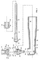
- a dental prophylaxis angle 8 comprises a unitary housing 10 defining a main passageway 12 which receives an elongate drive shaft 14. Housing 10 also defines an ancillary passageway 16 which communicates with the main passageway 12 and extends at an angle of 90 degrees relative thereto.
- a cup holder 18 is rotatably disposed in ancillary passageway 16. The cup holder 18 is rotatably retained in housing 10 in part via a cylindrical projection 17 which extends into an axial bore 19 in cup holder 18. The projection provides axial stability during rotation and assists in maintaining gear alignment.
- the cup holder 18 is provided with a plurality of gear teeth 20 which mesh with a plurality of gear teeth 22 on an inner end of drive shaft 4, to rotatably drive the cup holder.
- a prophy cup 24 made of a flexible polymeric material is mounted to the cup holder 18 via a ball and socket joint 26.
- Cup holder 18 has a base 29 from which a post 30 extends having a ball 31 on the end.
- the ball 31 is received in a spherical pocket 32 in the prophy cup 24.
- a tapered passage 33 leads to the pocket, to ease insertion of the ball into the pocket.
- the tapered passage also allows a degree of tilt when using the prophy cup.
- the prophy cup 24 has a flexible cylindrical skirt 34 which surrounds an annular groove 35.
- the groove 35 receives an upwardly extending annular seat 36 of the cup holder 18, with a gap 37 provided between a top wall 38 of the seat and a base wall 39 of the groove.
- a second gap 40 is also provided between a lower surface 41 of the prophy cup and the base 29 when the ball is received in the pocket.
- the seat 36 has an outer surface 42 which is inclined at an angle with respect to a longitudinal axis 43 of the cup holder 18. As illustrated in Fig. 3, as the prophy cup 24 pivots about the ball 31, for example, when moving over a contoured tooth surface, the skirt 34 engages and slides over the inclined outer surface 42 of seat 36, until the top wall abuts the base wall, and the lower surface 41 abuts the base 29, thereby enhancing the flexibility of the prophy cup. 24, without jeopardizing cup stability, when the cup is removed from the tooth surface, the flexible shirt guides the cup to return to its upright position.
- the prophy cup is made of a flexible material such as natural or synthetic rubber, silicone or another elastomer.
- the housing and cup holder are typically made of a rigid plastic, as is the bearing, and there are numerous materials available for producing these parts.
- the drive shaft is also produced of plastic, sufficiently rigid to transmit the rotational motion but having a degree of flexibility to accommodate the neck bend. One familiar with prophy angles can readily determine suitable materials for each component.
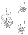
- prophy cup 24 is provided with four drive projections 44 which extend into the groove 35.
- the seat 36 is provided with four complimentary slots 45 for receiving the projections.
- the projections 44 engage the slots 45 in the manner of a gear coupling for transmitting rotary force from the cap holder 18 to prophy cup 24.
- the slots and projections are sized to accommodate tilting displacement without disengagement. That is, each component is of a sufficient length to allow displacement along the longitudinal axis during tilting without separation.
- This drive coupling enables the cup to tilt on the ball 31, thereby facilitating the pivoting of prophy cup 24 during use.
- the number and shapes of the projections and slots can vary, and the invention is not limited to the illustrated arrangement.
- a bearing 46 is rotatably disposed in the main passageway 12 about a bearing portion 47 of the drive shaft 14.
- the bearing 46 has a snap-lock element 48 projecting from a resilient tab 49 into a recess or aperture 50 provided in the housing 10. The snap-lock coupling of bearing 46 to housing 10 fixes the position of the bearing and holds the bearing stationary with respect to the housing while rotatably supporting the drive shaft 14.
- the aperture is shown as a through passage to allow disassembly, if desired, by pressing in the locking element and pulling on the end of the drive shaft.
- a depression type aperture rather than a through aperture may be used.
- Gear teeth 22 extend from a widened portion 52 of the drive shaft 14, The widened portion 52 is held in position by an inner bearing surface 53.
- the bearing 46 and the widened shaft portion 52 cooperate to hold the drive shaft 14 in alignment with the cup holder gears 20.
- the position of the drive shaft 14 relative to the cup holder 18 is further maintained by a longitudinal extension 54 of the shaft 14.
- the extension 54 promotes meshing of gear teeth 20 and 22 by limiting movement of the drive shaft 14 towards the cup holder 18.
- the extension 54 and the bearing surface 53 cooperate to prevent axial movement of the drive shaft.
- the extension 54 also serves to prevent removal of the cup holder as it is received within a circumferential groove 55 about a stabilizing leg 56 of the cup holder. This leg contains the axial bore 19, and also has a step 57 which prevents removal of the cup holder through engagement with the extension 54.
- the bearing 46 is formed with a longitudinally extending resilient tab 49 on which the snap-lock element 48 is disposed.
- the tab 49 is located between a pair of spaced longitudinally extending slots or cutouts 58 and 60 in bearing 46.
- these slots are received by corresponding raised bosses 61 in the housing 10 which additionally has along the main passageway 12, a groove 62 longitudinally aligned with aperture 50 for facilitating insertion of the snap-lock element 48 into the recess.
- the tab is bent inwardly as it travels along the groove until the element 48 enters the aperture. This locks the bearing to prevent rotation or withdrawal, thus completing the assembly.
- the prophylaxis angle thus is produced with a minimum number of parts, that is, a unitary housing, a drive shaft, a bearing and a cup holder. Each part is integrally produced ready for assembly.
- the cup holder is placed in the passage way 16.
- the drive shaft is inserted until the gears engage and then the bearing is pushed into the housing, over the drive shaft until the element 48 snaps into the aperture 50.
- a single locking element holds all the components together.
- An additional advantage of the invention is that the bearing is forwardly located and relatively short and consequently, once assembled, the housing may be bent without interference with the drive components.
- a prophy angle 65 has a bend 66 at an angle of about 15 degrees relative to the axis 67.
- the bend 66 is adjacent to a snap lock bearing 68 having a locking element 69 residing in a recess or aperture 70.
- the bearing resides in a forward bent portion 71 of a housing 72. In this housing, the optional longitudinal groove and raised bosses were not used.
- a "c" shaped receptacle 73 maintains the axial alignment of a cup holder 74 by surrounding a collar 75 on a stabilizing leg 76 of the cup holder.
- the "c" shaped receptacle is best seen in Fig. 7a. Again, this works in cooperation with an extension 77 on a drive shaft 78, to prevent removal of the cup holder from the housing.
- the prophy angle 65 includes the drive shaft 78 which has an end 79 extending beyond an end 80 of the housing. This allows guidance of the end 79 into a hand piece (not shown) connected to a drive motor (not shown). These drive shafts are typically made of plastic and thus are easily bent with light pressure to the phantom position shown in Fig. 7a, for entry into the hand piece.
- the bearing 68 assures that despite the bend, proper rotational motion is transmitted to a prophy cup 81 mounted in the cup holder 74.
Landscapes
- Health & Medical Sciences (AREA)
- Oral & Maxillofacial Surgery (AREA)
- Dentistry (AREA)
- Epidemiology (AREA)
- Life Sciences & Earth Sciences (AREA)
- Animal Behavior & Ethology (AREA)
- General Health & Medical Sciences (AREA)
- Public Health (AREA)
- Veterinary Medicine (AREA)
- Dental Tools And Instruments Or Auxiliary Dental Instruments (AREA)
- Dental Preparations (AREA)
Claims (11)
- Zahnprophylaxe-Winkelstück (8) mit:einem einheitlichen Gehäuse (10), das einen Hauptkanal (12) und einen Hilfskanal (16) definiert, welcher unter einem beträchtlichen Winkel zu diesem verläuft;einer Antriebswelle (14), die durch den Hauptkanal verläuft;einem Napfhalter (18), der in dem Hilfskanal drehbar gelagert ist, wobei der Napfhalter mit der Antriebswelle drehfest verbunden ist; undeinem flexiblen Prophylaxe-Napf (24), der an dem Napfhalter angebracht ist,welches Zahnprophylaxe-Winkelstück dadurch gekennzeichnet ist, dass der Napf mit dem Napfhalter über ein Kugelgelenk (26) mit Kugel (31) und Pfanne verbunden ist, der Napf eine flexible Schürze (34) hat, die eine Ringnut (35) bildet, der Napfhalter einen ringförmigen Sitz (36) hat, der in die Nut (35) vorsteht, und Spalte (40, 37) zwischen den gegenüberliegenden oberen (38) und unteren (39) Flächen des Napfhalters bzw. des Napfes vorgesehen sind, um eine Drehbewegung des Napfes um das Kugelgelenk im Betrieb zu ermöglichen.
- Zahnprophylaxe-Winkelstück nach Anspruch 1, bei dem der Sitz eine Außenfläche (42) hat, die unter einem Winkel bezüglich einer Längsachse des Napfhalters geneigt ist, wobei die Schürze an dieser äußeren Fläche angreift und sich während des Betriebs des Zahnprophylaxe-Winkelstücks über die geneigte Fläche biegt.
- Zahnprophylaxe-Winkelstück nach Anspruch 1, bei dem der Napf Mitnehmer (44) hat, die sich in die Nut erstrecken, wobei der Sitz einwärts gerichtete Zähne hat, die mit den Mitnehmern zum Antreiben des Napfes kämmen.
- Zahnprophylaxe-Winkelstück nach Anspruch 1, das ferner ein Lager (46) aufweist, das in dem Hauptkanal um die Antriebswelle herum drehbar angeordnet ist, wobei das Lager ein Rastglied (48) hat, das in eine Ausnehmung (50) in dem Gehäuse vorsteht, wodurch eine Längsposition des Lagers bezüglich des Gehäuses festgelegt und die Antriebswelle in Antriebseingriff mit dem Napfhalter gehalten wird, wobei die Antriebswelle ein inneres Ende hat, das mit dem Napfhalter in Eingriff steht, und das innere Ende mit einem erweiterten Abschnitt (52) versehen ist, der mit dem Lager in Gleitberührung steht.
- Zahnprophylaxe-Winkelstück (8, 65) nach Anspruch 1, dadurch gekennzeichnet, dass die Antriebswelle eine Verlängerung (54) hat, die innerhalb einer Umfangsnut um einen Schenkel (56) des Napfhalters herum angeordnet ist, um axiale Verstellungen der Antriebswelle zu begrenzen und den Napfhalter in dem Hilfskanal zu halten; und
ein Lager (46) in einem vorderen Ende des Hauptkanals um die Antriebswelle herum drehbar angeordnet ist und das Lager ein einzelnes Verriegelungselement (48) hat, das in einer Ausnehmung (50) im Gehäuse verriegelt ist, um das Lager bezüglich des Gehäuses festzulegen und die Antriebswelle in Antriebseingriff mit dem Napfhalter zu halten. - Zahnprophylaxe-Winkelstück nach Anspruch 5, bei dem die Antriebswelle ein Antriebsende hat, das mit dem Napfhalter in Eingriff steht, wobei das Antriebsende einen erweiterten Abschnitt (52) in Kontakt mit einer vorderen Fläche (53) des Lagers hat.
- Zahnprophylaxe-Winkelstück nach Anspruch 6, bei dem die Napfhalter-Welle mit dem Napfhalter über kämmende Zähne (22) der Antriebswelle verbunden ist, die mit entsprechenden Zähnen (20) an dem Napfhalter in Eingriff stehen.
- Zahnprophylaxe-Winkelstück nach Anspruch 5, bei dem eine Lasche (49) des Verriegelungselementes (48) durch zwei längs verlaufende Schlitze (58, 60) in dem Lager definiert ist.
- Zahnprophylaxe-Winkelstellung nach Anspruch 5, bei dem das Gehäuse eine Innenfläche längs des Hauptkanals hat, welche Innenfläche eine Nut (62) hat, die in Längsrichtung zu der Ausnehmung ausgerichtet ist, um das Einsetzen des Rastgliedes in die Ausnehmung zu erleichtern.
- Zahnprophylaxe-Winkelstellung nach Anspruch 5, bei dem der Napfhalter eine Basis (29) mit einem aufwärts verlaufenden Pfosten (30) hat und eine Kugel (31) an dem Ende des Pfostens angeordnet ist, um ein Kugelgelenk (26) zu bilden, wobei der Napfhalter einen ringförmigen Sitz (36) mit einer geneigten Außenfläche (42) und einwärts beabstandeten vorstehenden Zahnabschnitten zum Antreiben eines im Napfhalter angeordneten Werkzeuges hat.
- Zahnprophylaxe-Winkelstück (65) nach Anspruch 5, bei dem das Gehäuse einen Halsabschnitt (66) hat, der unter einem Winkel von bis zu 15° gebogen ist.
Applications Claiming Priority (3)
| Application Number | Priority Date | Filing Date | Title |
|---|---|---|---|
| US71875096A | 1996-09-23 | 1996-09-23 | |
| US718750 | 1996-09-23 | ||
| PCT/US1997/013133 WO1998011843A1 (en) | 1996-09-23 | 1997-07-25 | Dental prophylaxis angle and a pivotable prophy cup therefor |
Publications (2)
| Publication Number | Publication Date |
|---|---|
| EP0927004A1 EP0927004A1 (de) | 1999-07-07 |
| EP0927004B1 true EP0927004B1 (de) | 2004-05-12 |
Family
ID=24887360
Family Applications (1)
| Application Number | Title | Priority Date | Filing Date |
|---|---|---|---|
| EP97934311A Expired - Lifetime EP0927004B1 (de) | 1996-09-23 | 1997-07-25 | Vorrichtung zur zahnprophylaxe sowie dazugehöriger schwenkbarer napf |
Country Status (7)
| Country | Link |
|---|---|
| US (1) | US6053732A (de) |
| EP (1) | EP0927004B1 (de) |
| AT (1) | ATE266366T1 (de) |
| AU (1) | AU729347B2 (de) |
| CA (1) | CA2265867C (de) |
| DE (1) | DE69729105T2 (de) |
| WO (1) | WO1998011843A1 (de) |
Families Citing this family (30)
| Publication number | Priority date | Publication date | Assignee | Title |
|---|---|---|---|---|
| US6527552B2 (en) * | 2001-06-13 | 2003-03-04 | Young Dental Manufacturing I, L.L.C. | Lubricated disposable prophylaxis angle |
| WO2004093719A2 (en) | 2003-04-23 | 2004-11-04 | The Procter & Gamble Company | Electric toothbrushes |
| FR2858541A1 (fr) * | 2003-08-04 | 2005-02-11 | Micro Mega Int Mfg Sa | Contre-angle utilise en endodontie |
| FR2858540B1 (fr) * | 2003-08-04 | 2006-03-17 | Micro Mega Int Mfg Sa | Dispositif de preparation canalaire |
| FR2861578B1 (fr) * | 2003-11-05 | 2006-02-03 | Micro Mega Int Mfg Sa | Dispositif de fixation amovible et d'entrainement d'un instrument dentaire dans la tete d'une piece a main |
| US20080176184A1 (en) * | 2003-11-05 | 2008-07-24 | Jean-Marie Badoz | Device for removably fixing and driving a tool in the head of a handpiece |
| US7052644B2 (en) * | 2003-11-17 | 2006-05-30 | Graham Packaging Pet Technologies, Inc. | Continuous production of molded plastic containers |
| US7070412B2 (en) * | 2004-08-02 | 2006-07-04 | Stadeker Wilkie J | Self-contained dental prophylaxis angle with offset rotational axis |
| US7255559B2 (en) * | 2004-08-30 | 2007-08-14 | Pac-Dent International, Inc. | Disposable dental prophy angle with secure retention mechanism |
| EP1642547B1 (de) * | 2004-09-30 | 2009-12-02 | W & H Dentalwerk Bürmoos GmbH | Dentales Handstück mit einer Wurzelkanallängen-Messfunktion |
| US8353700B2 (en) * | 2004-12-15 | 2013-01-15 | Andre Michaelian | Dental device and method of use |
| US20060127844A1 (en) * | 2004-12-15 | 2006-06-15 | Andre Michaelian | Dental device and method of use |
| DE102005016049A1 (de) * | 2005-04-07 | 2006-10-12 | Kaltenbach & Voigt Gmbh | Medizinisches Handstück mit einem abgewinkelten Schaft |
| US7422433B2 (en) * | 2005-07-26 | 2008-09-09 | Angstrom Manufacturing, Inc. | Prophy angle |
| US8123523B2 (en) | 2005-07-26 | 2012-02-28 | Angstrom Manufacturing, Inc. | Prophy angle and adapter |
| US7104796B1 (en) * | 2005-10-13 | 2006-09-12 | Hui-Tsu Chia | Disposable prophy angle for an electric tooth polisher |
| WO2009036462A2 (en) * | 2007-09-14 | 2009-03-19 | Discus Dental, Llc | Dental prophylaxis devices |
| US7955079B2 (en) * | 2007-12-20 | 2011-06-07 | Dentsply International, Inc. | Dental prophylaxis angle and handpiece assembly |
| US20100035205A1 (en) * | 2008-08-09 | 2010-02-11 | Daniel Wang | Non-90-Degree Ergonomically-Shaped Dental Prophylaxis Angle with a Straight Driving Shaft |
| US8302239B2 (en) * | 2009-07-10 | 2012-11-06 | Igor Lantsberg | Orbital electric toothbrush |
| USD674487S1 (en) | 2011-09-30 | 2013-01-15 | Dentsply International Inc. | Dental device connection adapter |
| USD687552S1 (en) | 2011-09-30 | 2013-08-06 | Dentsply International Inc. | Dental device connection adapter |
| CA2956060C (en) * | 2014-07-24 | 2023-12-12 | Crosstex International, Inc. | Prophy angle device and method of use |
| US9717566B2 (en) | 2015-01-27 | 2017-08-01 | Hu-Friedy Mfg. Co., Llc | Adjustable dental prophylaxis angle with axialy shiftable adjustment mechanism |
| US9259292B1 (en) | 2015-01-27 | 2016-02-16 | Hu-Friedy Mfg. Co., Llc | Adjustable dental prophylaxis angle with rotating adjuster |
| US9737375B2 (en) | 2015-06-11 | 2017-08-22 | Avid, Inc. | Dental handpiece and prophy angle |
| USD776815S1 (en) | 2015-06-11 | 2017-01-17 | Avid, Inc. | Dental handpiece nosecone |
| USD776814S1 (en) | 2015-06-11 | 2017-01-17 | Avid, Inc. | Dental prophy angle nosecone attachment feature |
| US20190321151A1 (en) * | 2018-04-24 | 2019-10-24 | Microcopy Ltd. | Dental prophy orbiter |
| USD1013873S1 (en) | 2022-06-17 | 2024-02-06 | Young Dental Manufacturing I, Llc | Prophy angle body |
Family Cites Families (17)
| Publication number | Priority date | Publication date | Assignee | Title |
|---|---|---|---|---|
| GB191124343A (en) * | 1911-11-02 | 1912-08-01 | Henry Milner | Improvements in Loom Shuttle Pegs or Spindles. |
| US3163934A (en) * | 1962-09-14 | 1965-01-05 | Adolph D Wiseman | Dental prophylaxis right angle hand piece |
| US3472045A (en) * | 1967-10-04 | 1969-10-14 | Alice E Nelsen | Dental polishing apparatus |
| US3478433A (en) * | 1968-04-15 | 1969-11-18 | George E Richmond | Tooth cleaning tool |
| US4123845A (en) * | 1976-12-17 | 1978-11-07 | Porta-Pro Incorporated | Self contained power actuated dental appliance |
| US4365956A (en) * | 1978-10-23 | 1982-12-28 | Young Dental Manufacturing Company | Cleaning cup |
| EP0029862B1 (de) * | 1979-11-29 | 1984-03-14 | Siemens Aktiengesellschaft | Zahnärztliches Handstück mit Vorrichtung zur lösbaren Verbindung zweier Handstückteile |
| DE3832694C3 (de) * | 1988-09-27 | 1996-04-25 | Geka Brush Georg Karl Gmbh | Auswechselapplikationsgerät für die Mundhygiene |
| US5040978A (en) * | 1989-12-22 | 1991-08-20 | Dentsply Research & Development Corp. | Dental prophy angle |
| US5062796A (en) * | 1990-07-17 | 1991-11-05 | Rosenberg Neil A | Dental handpiece |
| US5328369A (en) * | 1990-11-15 | 1994-07-12 | Young Dental Manufacturing Company | Dental prophylaxis angle |
| US5120220A (en) * | 1990-12-04 | 1992-06-09 | Biodental Technologies Corporation | Right angled dental hand piece |
| US5348473A (en) * | 1993-02-17 | 1994-09-20 | Kivlighan Jr Michael F | Medical tool |
| JPH06327699A (ja) * | 1993-05-25 | 1994-11-29 | Puromidento Kogyo:Yugen | プロフィーアングル |
| US5482461A (en) * | 1994-03-31 | 1996-01-09 | Yale; Joyce K. | Disposable prophy angle |
| US5484284A (en) * | 1994-07-28 | 1996-01-16 | Young Dental Manufacturing Company, Inc. | Dental prophylaxis tool and angle using it |
| US5642995A (en) * | 1995-08-16 | 1997-07-01 | Young Dental Manufacturing Company | Dental prophylaxis angle with seal protector |
-
1997
- 1997-07-25 AT AT97934311T patent/ATE266366T1/de not_active IP Right Cessation
- 1997-07-25 AU AU37400/97A patent/AU729347B2/en not_active Ceased
- 1997-07-25 DE DE69729105T patent/DE69729105T2/de not_active Expired - Fee Related
- 1997-07-25 EP EP97934311A patent/EP0927004B1/de not_active Expired - Lifetime
- 1997-07-25 CA CA002265867A patent/CA2265867C/en not_active Expired - Fee Related
- 1997-07-25 WO PCT/US1997/013133 patent/WO1998011843A1/en not_active Ceased
-
1998
- 1998-02-06 US US09/020,059 patent/US6053732A/en not_active Expired - Fee Related
Also Published As
| Publication number | Publication date |
|---|---|
| AU729347B2 (en) | 2001-02-01 |
| WO1998011843A1 (en) | 1998-03-26 |
| ATE266366T1 (de) | 2004-05-15 |
| DE69729105T2 (de) | 2005-05-12 |
| DE69729105D1 (de) | 2004-06-17 |
| US6053732A (en) | 2000-04-25 |
| EP0927004A1 (de) | 1999-07-07 |
| CA2265867A1 (en) | 1998-03-26 |
| CA2265867C (en) | 2007-05-29 |
| AU3740097A (en) | 1998-04-14 |
Similar Documents
| Publication | Publication Date | Title |
|---|---|---|
| AU729347B2 (en) | Dental prophylaxis angle and a pivotable prophy cup therefor | |
| US5902107A (en) | Disposable prophylaxis angle with adjustable head | |
| US7955079B2 (en) | Dental prophylaxis angle and handpiece assembly | |
| US5328369A (en) | Dental prophylaxis angle | |
| US8597022B2 (en) | Prophy angle and adapter | |
| EP0636344B1 (de) | Medizinisches Instrument zur Behandlung von Sinusitis | |
| JP4667038B2 (ja) | 内視鏡付属品装着アダプタ | |
| US7762813B2 (en) | Disposable prophylaxis angle | |
| US20080311541A1 (en) | Prophy angle | |
| US4321040A (en) | Endodontic instrument | |
| EP1598023A2 (de) | Medizinisches Handstück | |
| US20100035205A1 (en) | Non-90-Degree Ergonomically-Shaped Dental Prophylaxis Angle with a Straight Driving Shaft | |
| CN211674661U (zh) | 口腔工具传动组件和具有其的牙科种植机 | |
| US20230330322A1 (en) | Device for motorizing the movements of the piston of a fluid tank used in the medical environment | |
| EP0744928B1 (de) | Wegwerfbares dentales winkelhandstück | |
| HK1143943B (en) | Improved disposable prophylaxis angle | |
| HK1143943A (en) | Improved disposable prophylaxis angle |
Legal Events
| Date | Code | Title | Description |
|---|---|---|---|
| PUAI | Public reference made under article 153(3) epc to a published international application that has entered the european phase |
Free format text: ORIGINAL CODE: 0009012 |
|
| 17P | Request for examination filed |
Effective date: 19990423 |
|
| AK | Designated contracting states |
Kind code of ref document: A1 Designated state(s): AT BE CH DE DK ES FI FR GB GR IE IT LI LU NL PT SE |
|
| 17Q | First examination report despatched |
Effective date: 20020322 |
|
| GRAP | Despatch of communication of intention to grant a patent |
Free format text: ORIGINAL CODE: EPIDOSNIGR1 |
|
| GRAS | Grant fee paid |
Free format text: ORIGINAL CODE: EPIDOSNIGR3 |
|
| GRAA | (expected) grant |
Free format text: ORIGINAL CODE: 0009210 |
|
| AK | Designated contracting states |
Kind code of ref document: B1 Designated state(s): AT BE CH DE DK ES FI FR GB GR IE IT LI LU NL PT SE |
|
| PG25 | Lapsed in a contracting state [announced via postgrant information from national office to epo] |
Ref country code: NL Free format text: LAPSE BECAUSE OF FAILURE TO SUBMIT A TRANSLATION OF THE DESCRIPTION OR TO PAY THE FEE WITHIN THE PRESCRIBED TIME-LIMIT Effective date: 20040512 Ref country code: LI Free format text: LAPSE BECAUSE OF FAILURE TO SUBMIT A TRANSLATION OF THE DESCRIPTION OR TO PAY THE FEE WITHIN THE PRESCRIBED TIME-LIMIT Effective date: 20040512 Ref country code: FI Free format text: LAPSE BECAUSE OF FAILURE TO SUBMIT A TRANSLATION OF THE DESCRIPTION OR TO PAY THE FEE WITHIN THE PRESCRIBED TIME-LIMIT Effective date: 20040512 Ref country code: CH Free format text: LAPSE BECAUSE OF FAILURE TO SUBMIT A TRANSLATION OF THE DESCRIPTION OR TO PAY THE FEE WITHIN THE PRESCRIBED TIME-LIMIT Effective date: 20040512 Ref country code: BE Free format text: LAPSE BECAUSE OF FAILURE TO SUBMIT A TRANSLATION OF THE DESCRIPTION OR TO PAY THE FEE WITHIN THE PRESCRIBED TIME-LIMIT Effective date: 20040512 Ref country code: AT Free format text: LAPSE BECAUSE OF FAILURE TO SUBMIT A TRANSLATION OF THE DESCRIPTION OR TO PAY THE FEE WITHIN THE PRESCRIBED TIME-LIMIT Effective date: 20040512 |
|
| REG | Reference to a national code |
Ref country code: GB Ref legal event code: FG4D |
|
| REG | Reference to a national code |
Ref country code: CH Ref legal event code: EP |
|
| REG | Reference to a national code |
Ref country code: IE Ref legal event code: FG4D |
|
| REF | Corresponds to: |
Ref document number: 69729105 Country of ref document: DE Date of ref document: 20040617 Kind code of ref document: P |
|
| PG25 | Lapsed in a contracting state [announced via postgrant information from national office to epo] |
Ref country code: LU Free format text: LAPSE BECAUSE OF NON-PAYMENT OF DUE FEES Effective date: 20040725 |
|
| PG25 | Lapsed in a contracting state [announced via postgrant information from national office to epo] |
Ref country code: IE Free format text: LAPSE BECAUSE OF NON-PAYMENT OF DUE FEES Effective date: 20040726 |
|
| PG25 | Lapsed in a contracting state [announced via postgrant information from national office to epo] |
Ref country code: SE Free format text: LAPSE BECAUSE OF FAILURE TO SUBMIT A TRANSLATION OF THE DESCRIPTION OR TO PAY THE FEE WITHIN THE PRESCRIBED TIME-LIMIT Effective date: 20040812 Ref country code: GR Free format text: LAPSE BECAUSE OF FAILURE TO SUBMIT A TRANSLATION OF THE DESCRIPTION OR TO PAY THE FEE WITHIN THE PRESCRIBED TIME-LIMIT Effective date: 20040812 Ref country code: DK Free format text: LAPSE BECAUSE OF FAILURE TO SUBMIT A TRANSLATION OF THE DESCRIPTION OR TO PAY THE FEE WITHIN THE PRESCRIBED TIME-LIMIT Effective date: 20040812 |
|
| PG25 | Lapsed in a contracting state [announced via postgrant information from national office to epo] |
Ref country code: ES Free format text: LAPSE BECAUSE OF FAILURE TO SUBMIT A TRANSLATION OF THE DESCRIPTION OR TO PAY THE FEE WITHIN THE PRESCRIBED TIME-LIMIT Effective date: 20040823 |
|
| NLV1 | Nl: lapsed or annulled due to failure to fulfill the requirements of art. 29p and 29m of the patents act | ||
| REG | Reference to a national code |
Ref country code: CH Ref legal event code: PL |
|
| ET | Fr: translation filed | ||
| PLBE | No opposition filed within time limit |
Free format text: ORIGINAL CODE: 0009261 |
|
| STAA | Information on the status of an ep patent application or granted ep patent |
Free format text: STATUS: NO OPPOSITION FILED WITHIN TIME LIMIT |
|
| 26N | No opposition filed |
Effective date: 20050215 |
|
| REG | Reference to a national code |
Ref country code: IE Ref legal event code: MM4A |
|
| PG25 | Lapsed in a contracting state [announced via postgrant information from national office to epo] |
Ref country code: PT Free format text: LAPSE BECAUSE OF NON-PAYMENT OF DUE FEES Effective date: 20041012 |
|
| PGFP | Annual fee paid to national office [announced via postgrant information from national office to epo] |
Ref country code: DE Payment date: 20080807 Year of fee payment: 12 |
|
| PGFP | Annual fee paid to national office [announced via postgrant information from national office to epo] |
Ref country code: IT Payment date: 20080728 Year of fee payment: 12 Ref country code: FR Payment date: 20080718 Year of fee payment: 12 |
|
| PGFP | Annual fee paid to national office [announced via postgrant information from national office to epo] |
Ref country code: GB Payment date: 20080806 Year of fee payment: 12 |
|
| GBPC | Gb: european patent ceased through non-payment of renewal fee |
Effective date: 20090725 |
|
| REG | Reference to a national code |
Ref country code: FR Ref legal event code: ST Effective date: 20100331 |
|
| PG25 | Lapsed in a contracting state [announced via postgrant information from national office to epo] |
Ref country code: FR Free format text: LAPSE BECAUSE OF NON-PAYMENT OF DUE FEES Effective date: 20090731 |
|
| PG25 | Lapsed in a contracting state [announced via postgrant information from national office to epo] |
Ref country code: GB Free format text: LAPSE BECAUSE OF NON-PAYMENT OF DUE FEES Effective date: 20090725 |
|
| PG25 | Lapsed in a contracting state [announced via postgrant information from national office to epo] |
Ref country code: DE Free format text: LAPSE BECAUSE OF NON-PAYMENT OF DUE FEES Effective date: 20100202 |
|
| PG25 | Lapsed in a contracting state [announced via postgrant information from national office to epo] |
Ref country code: IT Free format text: LAPSE BECAUSE OF NON-PAYMENT OF DUE FEES Effective date: 20090725 |