EP0927079B1 - Trennzentrifuge - Google Patents
Trennzentrifuge Download PDFInfo
- Publication number
- EP0927079B1 EP0927079B1 EP97937692A EP97937692A EP0927079B1 EP 0927079 B1 EP0927079 B1 EP 0927079B1 EP 97937692 A EP97937692 A EP 97937692A EP 97937692 A EP97937692 A EP 97937692A EP 0927079 B1 EP0927079 B1 EP 0927079B1
- Authority
- EP
- European Patent Office
- Prior art keywords
- housing
- centrifugal separator
- legs
- vane
- cage
- Prior art date
- Legal status (The legal status is an assumption and is not a legal conclusion. Google has not performed a legal analysis and makes no representation as to the accuracy of the status listed.)
- Expired - Lifetime
Links
- 238000000926 separation method Methods 0.000 title claims abstract description 15
- 238000006243 chemical reaction Methods 0.000 claims description 13
- 230000000694 effects Effects 0.000 claims description 7
- 239000002184 metal Substances 0.000 claims description 5
- 239000012530 fluid Substances 0.000 claims description 4
- 238000009825 accumulation Methods 0.000 claims description 2
- 239000007788 liquid Substances 0.000 abstract description 49
- 230000009194 climbing Effects 0.000 abstract description 4
- 241000239290 Araneae Species 0.000 abstract description 3
- 239000000356 contaminant Substances 0.000 abstract description 3
- 239000010705 motor oil Substances 0.000 abstract description 2
- 239000003921 oil Substances 0.000 abstract 2
- 239000000314 lubricant Substances 0.000 description 4
- 238000009987 spinning Methods 0.000 description 3
- 238000005452 bending Methods 0.000 description 2
- 238000002485 combustion reaction Methods 0.000 description 2
- 230000005484 gravity Effects 0.000 description 2
- 239000010687 lubricating oil Substances 0.000 description 2
- 238000005461 lubrication Methods 0.000 description 2
- 230000002093 peripheral effect Effects 0.000 description 2
- 238000003466 welding Methods 0.000 description 2
- 230000004888 barrier function Effects 0.000 description 1
- 230000015572 biosynthetic process Effects 0.000 description 1
- 238000010276 construction Methods 0.000 description 1
- 230000001419 dependent effect Effects 0.000 description 1
- 230000001627 detrimental effect Effects 0.000 description 1
- 238000003475 lamination Methods 0.000 description 1
- 238000004519 manufacturing process Methods 0.000 description 1
- 239000002245 particle Substances 0.000 description 1
- 238000007789 sealing Methods 0.000 description 1
- 239000007787 solid Substances 0.000 description 1
- 238000013022 venting Methods 0.000 description 1
Images

Classifications
-
- B—PERFORMING OPERATIONS; TRANSPORTING
- B04—CENTRIFUGAL APPARATUS OR MACHINES FOR CARRYING-OUT PHYSICAL OR CHEMICAL PROCESSES
- B04B—CENTRIFUGES
- B04B5/00—Other centrifuges
- B04B5/005—Centrifugal separators or filters for fluid circulation systems, e.g. for lubricant oil circulation systems
Definitions
- This invention relates to centrifugal separation apparatus for separating particulate contaminants from liquids, such as engine lubricants, passed therethrough, and in particular relates to the efficient drainage of low viscosity liquids from such apparatus.
- Centrifugal separators are well known for use within the lubrication systems of vehicle internal combustion engines as efficient means for removing very small particulate contaminants from the constantly recirculated liquid lubricant over a long period of operation.
- Such centrifugal separators are usually of the self-powered type, in which a separation rotor comprising a canister is supported for rotation about a rotor axis within a housing, the canister being supplied with liquid lubricant at elevated pressure along the axis and said liquid being forced from the base of the canister (or other peripheral wall) by way of substantially tangentially-directed jet reaction nozzles, the reaction to said ejection causing the rotor canister to spin at high speed about the axis and thereby cause solid particles to migrate from the liquid passing through the canister and agglomerate on the peripheral walls thereof.
- the jet or reaction nozzles are directed substantially tangentially with respect to the rotation axis, at least in a plane orthogonal to the axis, so that jets of liquid which leave the rotor canister are instantaneously tangential to the fastly spinning rotor.
- the rotor canister may also be impeded in rotation by droplets of lubricant emitted by the nozzles which splashes from the surfaces within the housing.
- the lubricant Whilst this reduces the tendency to splash and impede rotation to some extent, but not completely (and for which reason the axes of the reaction nozzles may be declined towards the floor of the housing), the lubricant is incident on the wall and/or floor at such angle as to cause this liquid to circulate around the housing as it falls towards the floor thereof and the drain.
- Patent specifications GB 2049494 and 2120134 describe a centrifugal separator in which the floor of a circularly cylindrical housing is in the form of a substantially conical funnel leading to a central, or axial, drainage duct.
- the centrifugal separation rotor comprises a canister mounted for rotation within the housing (from the side wall of which it is separated by only a small radial clearance) on an axle which is supported, with respect to the housing, raised above the floor by a cage or spider comprising an array of divergent legs separated circumferentially by drainage apertures for the liquid ejected from the rotor.
- a vortex of liquid with a higher viscosity tends to have a more uniform structure and surface on which the newly ejected liquid impinges and merges with uniform results
- a vortex of liquid with a low viscosity is found to have local turbulence within the body of the vortex and out of its surface and a tendency for both the liquid of the vortex and liquid ejected from the rotor that is incident on the vortex to splash and froth in the proximity of the rotor to the extent that the presence per se of such vortex separately from its climbing to fill the gap between rotor canister and housing, is a source of impedance to canister rotation detracting from the separation efficiency.
- the present invention concerns a self-powered centrifugal separator according to claim 1.
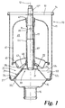
- a centrifugal separator 10 for use in the lubrication system of a vehicle internal combustion engine comprises a housing 11 in the form of a right circular cylinder centred on longitudinal axis 12 and open at one end 13.
- the housing is surrounded thereat by a sealing element 14 for mounting against a surface of the vehicle engine (not shown) which serves to close off the end of the housing and from which the housing operably depends.
- the other end of the housing is formed as a floor 15 which tapers as a funnel to a coaxial drainage duct 16.
- An axle 17 extends along the longitudinal axis 12 within the housing from a first axle end region 17', at which it is secured to a mount 20, to a second end region 17" having a threaded periphery by way of which the axle, and the separator as a whole, is removably secured to the vehicle engine.
- the mount 20 comprises a cage or spider 21 having a central mounting region 22, to which the axle end region 17' is secured spaced with respect to the floor 15, and a surrounding apertured drainage region, indicated at 23, extending radially and axially to the housing.
- the drainage region of the cage comprises an array of legs 25 1 , 25 2 , 25 3 diverging with respect to each other radially outwardly from the central mounting region and separated in a circumferential direction by drainage apertures 26 1 , 26 2 , 26 3 , said legs at the ends thereof adjacent the housing being jointed by an annular rim 27 in contact with the housing wall continuously about the periphery.
- the annular rim is curled to conform to the comer of the housing between the side wall and floor to align the axes of the axle and housing, and is secured to the housing by welding or the like, whereby the housing is secured with respect to the vehicle by way of the axle 17. That is, the axle depends from the vehicle and the housing depends from the axle.
- the cage is formed from a flat metal sheet by stamping out the drainage apertures 26 1 etc and then deforming it axially to provide said central mounting region, legs and annular rim integrally,
- the cage appears in elevation with the aperture drainage region as a truncated cone and the legs and drainage apertures defining a frusto conical plane within the housing.
- the legs 25 1 , etc of the cage are provided with strength to take axial mounting loads by means of pressed ribs or embossment 28 1 , 28 2 28 3 .
- a correspondingly legged bracing member 30, having a central region 31 and integral legs 32 1 etc, is disposed adjacent to the cage sheet with the legs overlying and joined to each other and the central mounting regions 22 and 31 spaced axially as a 'box section' into which the end region 17' of the axle is mounted.
- the axle 17 contains a passage extending from the end 17" and opening by way of transverse aperture 35.
- a centrifugal separation rotor 40 in the form of an annular canister having an integral sidewall and top portion 41 and base portion 42 containing an array of jet reaction nozzles, only one of which is shown at 43.
- the portions 41 and 42 surround a tubular member 44 which extends for the length of the rotor and defines an annular enclosure 45 within the rotor, the tubular member 44 being apertured at 46 to receive liquid from the axle aperture 35 and further carrying at opposite ends thereof bearing bushes 47 and 48 by way of which the rotor is able to undertake high speed rotation about the axle.
- the jet reaction nozzles 43 et al in the base of the rotor are directed substantially tangentially with respect to the longitudinal axis 12 and possibly slightly declined towards the floor of the housing, such arrangement being conventional to avoid, as far as is feasible, the liquid from the reaction jets which impinges against the wall of the housing from splashing against the rotor and disrupting its smooth rotation.
- the circular cross section of the housing encourages the discharged liquid to circulate around the housing, low viscosity liquid tending on the one hand to swirl more readily and rapidly but on the other hand more turbulently and presenting a rough surface, so that frothing and splashing of the vortex liquid itself and subsequently ejected liquid which is incident upon the liquid of the vortex is more likely to froth and splash and impinge detrimentally on the rotor canister.
- low liquid viscosities it is perceived as being the presence per se of a vortex of undrained liquid that is detrimental to rotation efficiency, irrespective of the effects of such vortex climbing the housing wall towards the rotor.
- vortex disruption means comprising associated with each radially and axially extending leg of the cage a deflection vane 51 1 , 51 2 , 51 3 respectively which extends from the leg in the same direction as the rotation of the rotor and overlying a part of the cage drainage region 26 1 , 26 2 , 23 3 respectively.
- Each vane such as 51 1
- the vane extends in the same direction as rotation of the rotor, overlying the cage drainage region aperature 26 1 that is, in a generally tangential direction in which it would intersect the side wall of the housing, but also is bent with respect to the edge of the leg in a direction towards the wall so that it intrudes into the region above the drainage region through which the reaction jets are ejected such that its lower surface serves to intercept such jets at appropriate rotational positions of the rotor.
- the ejected liquid which is incident upon such surface and relatively dose to the nozzles from which it issues, is deflected in a generally downward direction towards the drainage aperature 26 1 ; by such direction change a reaction boost may be imported to the rotor in its direction of spin but most importantly the liquid is prevented from contributing to a circumferential vortex flow of such ejected liquid about the side wall and rim 27.
- a reaction jet impinge directly upon the deflection vane, it impinges upon the housing side wall which deflects it circumferentially and by gravitational forces, impinge upon any liquid attempting to circulate as a vortex above rim 27.
- the deflection vane extends also to the vicinity of the side wall of the housing and any part of it effected by the annular rim 27.
- the vane 51 1 has a first edge 52 1 which extends substantially parallel to, the side wall being inclined to the longitudinal axis 12 in accordance with the deflection of the vane; it has a second edge 53 1 which extends from the end of the first edge to the vicinity of the rotor mounting region.
- the deflection vane extends from the leg to the extent that the second edge extends (in plan view) in a substantially radial direction towards the housing wall.
- the intersection between side wall and rim 27 is both cranked, in respect of the side wall locating the rim and the additional thickness of the rim, and curved by the curled form of the rim. Therefore it is convenient to cut the edge of the more blank before bending so that it conforms closely to the shape locally.
- the first edge 52 1 is conveniently straight, notwithstanding that it is intended to lie against a side wall curved in the circumferential direction, providing that any part of the edge is closer to the side wall than the separation between rotor canister and side wall.
- the first edge is arranged to contact the wall at one or both edges, but contact is not essential if the maximum spacing is not exceeded, permitting the vane to be set with assembly of the cage prior to disposal within the housing.
- vane 25 1 does not require securing to the housing, insofar as the cage rim 27 is (or may be) secured by spot welding to the housing the first edge of the vane may also be secured directly to the housing.
- vane 25 1 is of course applicable to the other vanes 25 2 and 25 3 .
- Each vane is conveniently a flat plane so that liquid ejected from the rotor canister in a tangential direction is deflected inwardly perpendicularly to the legs/drainage apertures whilst being a simple structure to manufacture, but if desired the vane may have a curvature along and/or across all or part of it to modify the redirection of the liquid or disruption of any vortex tending to form.
- each vane overlies the respective drainage aperture, to an extent which does not interfere with the effective area as seen liquid above it, by bending the vane upwardly towards the rotor and housing. It will be appreciated that if desired the vane may be less inclined, if at all, and extend further in a circumferential direction until intersection with the side wall, that is, tangentially.
- each deflection vane may be formed integrally with either layer of such laminated leg structure or even formed non-integrally, being either secured to any such leg structure or, in the case of such laminated leg structure, being sandwiched between laminations.
- Any deflection vane may be formed of other than the above-mentioned sheet metal, provided it is compatible with the operating conditions encountered within the housing.
- axle mount cage may be formed substantially as described but omitting the bracing member, which structural form limits only the options available for mounting the deflection vanes.
- axle mount cage may be formed with other than discrete identifiable legs separated by arcuate drainage apertures, for example, as a mesh or perforated sheet structure, but by appropriate construction one or more such deflection vanes may be employed attached to such mount or separately mounted within the housing between the mount and rotor.
- centrifugal separator structure described above has a fixed axle which supports and defines a rotation axis for the separation rotor canister. It will be appreciated that the present invention is applicable without change where the separation rotor is of the type that has an integral rotatable spindle which is mounted in place of the axle.
- the floor of the housing need not be of the funnel shape of the above-described embodiment, as such effects occur with substantially 'flat' floors where such rotational motion is permitted to build up in the ejected fluid.
Landscapes
- Centrifugal Separators (AREA)
- Cyclones (AREA)
- Lubrication Details And Ventilation Of Internal Combustion Engines (AREA)
Claims (13)
- Eine eigenbetriebene Trennzentrifuge (10), umfassend
ein Gehäuse (11), das durch eine zylindrische Seitenwand und einen Boden (15) definiert wird, wobei die Trennzentrifuge so ausgestaltet ist, dass ein Ablaufen einer Flüssigkeit aus dem Gehäuse in einen Ablaufkanal (16) bewirkt wird,
ein Gestell (21), das einen zentralen Befestigungsbereich (22) aufweist,
wobei dieses so gekoppelt ist, dass ein Trennzentrifugenrotor (40) mit Beabstandung zum Gehäuseboden gehalten wird und der Rotor vorgesehen ist, um Flüssigkeit bei erhöhtem Druck aufzunehmen und über im wesentlichen tangential ausgerichtete Strahldüsen (43) in das Gehäuse abzugeben, wo die Flüssigkeit in einer zuvor festgelegten Richtung um die Rotationsachse (12) rotiert, sowie einen umgebenden geöffneten Ablaufbereich (23), der sich bis zum Gehäuse erstreckt,
eine Wirbeltrenneinrichtung (50), welche einsetzbar ist, um eine Akkumulation der ausgeströmten Flüssigkeit innerhalb des Gehäuses zu verhindern, dadurch gekennzeichnet, dass diese Wirbeltrenneinrichtung mindestens einen Umleitungsflügel (511, 512, 513) umfasst, welcher einen Teil des Ablaufbereiches am Gestell in der zuvor bestimmten Rotationsrichtung des Rotors überdeckt,
wobei die erste Kante (521) des Flügels (511) im wesentlichen parallel zur Gehäuseseitenwand verläuft, weniger beabstandet ist als Seitenwand und Zentrifugenrotor sowie hinsichtlich der Rotationsachse in vorher bestimmter Rotationsrichtung des Rotors geneigt ist, und mit einer zweiten Kante (531), die vom Ende der ersten Kante bis in die Nähe des zentralen Befestigungsbereiches reicht. - Trennzentrifuge nach Anspruch 1, dadurch gekennzeichnet, dass diese zweite Kante (531) des Flügels (511) so angeordnet ist, dass sie sich im wesentlichen radial zum Gehäuse erstreckt.
- Trennzentrifuge nach Anspruch 1 oder 2, dadurch gekennzeichnet, dass mindestens ein Flügel (511) im wesentlichen eben ist.
- Trennzentrifuge nach Anspruch 1 oder 2, dadurch gekennzeichnet, dass die Fläche des Flügels (511) gebogen ist, um teilweise der Fläche des Ablaufbereiches (23) innerhalb des Gehäuses zu folgen.
- Trennzentrifuge nach einem der Ansprüche 1 bis 4, dadurch gekennzeichnet, dass die erste Kante (521) gerade und so angeordnet ist, dass sie die Seitenwand an mindestens einem Ende dieser Kante berührt.
- Trennzentrifuge nach einem der Ansprüche 1 bis 5, dadurch gekennzeichnet, dass der geöffnete Ablaufbereich (23) des Gestells eine Anordnung von Stegen (251) aufweist, die im wesentlichen radial von dem zentralen Befestigungsbereich nach außen hin zum Gehäuse verlaufen und von Ablauföffnungen (261..) in Umfangsrichtung getrennt sind.
- Trennzentrifuge nach Anspruch 6, dadurch gekennzeichnet, dass die Stege (251) an ihren am Gehäuse anliegenden Enden über einen ringförmigen Rand (27) verbunden sind und in stetigem Kontakt mit der Gehäusewand entlang des Umfangs stehen.
- Trennzentrifuge nach Anspruch 7, dadurch gekennzeichnet, dass der Rand (27) so gebogen ist, dass er der Verbindungsstelle zwischen Seitenwand des Gehäuses und Boden entspricht und der Flügel entsprechend dieser Biegung des Ringes ausgebildet ist.
- Trennzentrifuge nach einem der Ansprüche 1 bis 8, dadurch gekennzeichnet, dass die Stege (251) und/oder der ringförmige Rand (27) an der Verbindungsstelle zwischen Seitenwand und Boden (15) am Gehäuse befestigt sind.
- Trennzentrifuge nach einem der Ansprüche 6 bis 9, dadurch gekennzeichnet, dass mindestens einer der Stege (251...) einen sich davon erstreckenden Umleitungsflügel (511...) aufweist, der aus einem Stück mit einem Stegelement gebildet wird.
- Trennzentrifuge nach einem der Ansprüche 6 bis 9, dadurch gekennzeichnet, dass das Gestell (21) aus gepresstem Metallblech gebildet wird und einen zentralen Befestigungsbereich (31) mit daran angeformten Stege (321...) umfasst sowie eine den Stegen entsprechende Verstrebung (30), versehen mit den entsprechenden darüberliegenden und miteinander verbundenen Stegen (321...), und dass jeder Umleitungsflügel (511...) der Wirbeltrenneinrichtung (50) einstückig mit einem Steg (321...) der Verstrebung gebildet wird.
- Trennzentrifuge nach einem der Ansprüche 6 bis 9, dadurch gekennzeichnet, dass das Gestell (21) aus gepresstem Metallblech gebildet wird und einen zentralen Befestigungsbereich (31) mit daran angeformten Stege (321...) umfasst sowie eine den Stegen entsprechende Verstrebung (30), versehen mit den entsprechenden darüberliegenden und verbundenen Stegen, und dass jeder Umleitungsflügel (511...) der Wirbeltrenneinrichtung (50) mit den Stegen (251, 321) des Gestells mittels Verbundspritzgießtechnik zwischen Gestellblech und Verstrebung befestigt ist.
- Trennzentrifuge nach Anspruch 11 bzw. 12, dadurch gekennzeichnet, dass sich die Verstrebung (30) nicht in radialer Richtung zum Gehäuse erstreckt.
Applications Claiming Priority (3)
| Application Number | Priority Date | Filing Date | Title |
|---|---|---|---|
| GB9619366A GB2317128B (en) | 1996-09-17 | 1996-09-17 | Centrifugal separation apparatus |
| GB9619366 | 1996-09-17 | ||
| PCT/GB1997/002248 WO1998011994A1 (en) | 1996-09-17 | 1997-08-21 | Centrifugal separation apparatus |
Publications (2)
| Publication Number | Publication Date |
|---|---|
| EP0927079A1 EP0927079A1 (de) | 1999-07-07 |
| EP0927079B1 true EP0927079B1 (de) | 2002-05-08 |
Family
ID=10800037
Family Applications (1)
| Application Number | Title | Priority Date | Filing Date |
|---|---|---|---|
| EP97937692A Expired - Lifetime EP0927079B1 (de) | 1996-09-17 | 1997-08-21 | Trennzentrifuge |
Country Status (7)
| Country | Link |
|---|---|
| US (1) | US6196962B1 (de) |
| EP (1) | EP0927079B1 (de) |
| AT (1) | ATE217211T1 (de) |
| DE (1) | DE69712497T2 (de) |
| GB (1) | GB2317128B (de) |
| WO (1) | WO1998011994A1 (de) |
| ZA (1) | ZA978290B (de) |
Families Citing this family (44)
| Publication number | Priority date | Publication date | Assignee | Title |
|---|---|---|---|---|
| GB2322314B (en) * | 1997-02-21 | 2000-08-23 | Glacier Metal Co Ltd | Centrifugal separator |
| US6579220B2 (en) | 1999-07-07 | 2003-06-17 | Fleetguard, Inc. | Disposable, self-driven centrifuge |
| US6652439B2 (en) | 2000-04-04 | 2003-11-25 | Fleetguard, Inc. | Disposable rotor shell with integral molded spiral vanes |
| US6540653B2 (en) | 2000-04-04 | 2003-04-01 | Fleetguard, Inc. | Unitary spiral vane centrifuge module |
| US6602180B2 (en) | 2000-04-04 | 2003-08-05 | Fleetguard, Inc. | Self-driven centrifuge with vane module |
| US6551230B2 (en) | 2000-04-04 | 2003-04-22 | Fleetguard, Inc. | Molded spiral vane and linear component for a centrifuge |
| US6533712B1 (en) * | 2000-10-17 | 2003-03-18 | Fleetguard, Inc. | Centrifuge housing with oil fill port |
| US6364822B1 (en) | 2000-12-07 | 2002-04-02 | Fleetguard, Inc. | Hero-turbine centrifuge with drainage enhancing baffle devices |
| US6793615B2 (en) * | 2002-02-27 | 2004-09-21 | Fleetguard, Inc. | Internal seal for a disposable centrifuge |
| US7210195B2 (en) * | 2002-10-11 | 2007-05-01 | Rexair, Inc. | Integrated spider separator |
| RU2279318C1 (ru) * | 2004-11-09 | 2006-07-10 | Государственное образовательное учреждение высшего профессионального образования "Алтайский государственный технический университет им. И.И. Ползунова" (АлтГТУ) | Центробежный аппарат |
| US8075668B2 (en) | 2005-03-29 | 2011-12-13 | Dresser-Rand Company | Drainage system for compressor separators |
| GB2425077B (en) * | 2005-04-15 | 2009-11-18 | Mann & Hummel Gmbh | Centifrugal separator and rotor therefor |
| BRPI0716867A2 (pt) * | 2006-09-19 | 2013-10-15 | Dresser Rand Co | Vedação de tambor de separador rotativo |
| BRPI0718513B1 (pt) | 2006-09-21 | 2018-10-23 | Dresser Rand Co | conjunto de manuseio de fluido para uma máquina para fluidos |
| BRPI0717571B1 (pt) | 2006-09-25 | 2018-11-27 | Dresser Rand Co | carretel de conexão para conectar um invólucro do compressor com um invólucro do acionador de um sistema de compressão industrial |
| EP2066988A4 (de) | 2006-09-25 | 2012-01-04 | Dresser Rand Co | Kopplungsüberwachungssystem |
| BRPI0717087B1 (pt) | 2006-09-25 | 2018-10-16 | Dresser Rand Co | sistema de carretel conector para conectar um primeiro componente e um segundo componente de um sistema de compressão industrial |
| US8733726B2 (en) | 2006-09-25 | 2014-05-27 | Dresser-Rand Company | Compressor mounting system |
| US8231336B2 (en) | 2006-09-25 | 2012-07-31 | Dresser-Rand Company | Fluid deflector for fluid separator devices |
| EP2415507A1 (de) | 2006-09-26 | 2012-02-08 | Dresser-Rand Company | Verbesserte statische Flüssigkeitstrennungsvorrichtung |
| US8021290B2 (en) * | 2007-11-26 | 2011-09-20 | Honeywell International Inc. | Oil centrifuge for extracting particulates from a fluid using centrifugal force |
| BRPI0908051A2 (pt) | 2008-03-05 | 2015-08-11 | Dresser Rand Co | Conjunto compressor que inclui separador e bomba ejetora |
| US8062400B2 (en) | 2008-06-25 | 2011-11-22 | Dresser-Rand Company | Dual body drum for rotary separators |
| US7922218B2 (en) | 2008-06-25 | 2011-04-12 | Dresser-Rand Company | Shear ring casing coupler device |
| US8079805B2 (en) | 2008-06-25 | 2011-12-20 | Dresser-Rand Company | Rotary separator and shaft coupler for compressors |
| US8087901B2 (en) | 2009-03-20 | 2012-01-03 | Dresser-Rand Company | Fluid channeling device for back-to-back compressors |
| US8210804B2 (en) | 2009-03-20 | 2012-07-03 | Dresser-Rand Company | Slidable cover for casing access port |
| US8061972B2 (en) | 2009-03-24 | 2011-11-22 | Dresser-Rand Company | High pressure casing access cover |
| US8414692B2 (en) | 2009-09-15 | 2013-04-09 | Dresser-Rand Company | Density-based compact separator |
| US20110097216A1 (en) * | 2009-10-22 | 2011-04-28 | Dresser-Rand Company | Lubrication system for subsea compressor |
| US9095856B2 (en) | 2010-02-10 | 2015-08-04 | Dresser-Rand Company | Separator fluid collector and method |
| US8673159B2 (en) | 2010-07-15 | 2014-03-18 | Dresser-Rand Company | Enhanced in-line rotary separator |
| US8663483B2 (en) | 2010-07-15 | 2014-03-04 | Dresser-Rand Company | Radial vane pack for rotary separators |
| US8657935B2 (en) | 2010-07-20 | 2014-02-25 | Dresser-Rand Company | Combination of expansion and cooling to enhance separation |
| WO2012012143A2 (en) | 2010-07-21 | 2012-01-26 | Dresser-Rand Company | Multiple modular in-line rotary separator bundle |
| EP2614216B1 (de) | 2010-09-09 | 2017-11-15 | Dresser-Rand Company | Spülungsaktivierter gesteuerter strömungsabfluss |
| EP2659277B8 (de) | 2010-12-30 | 2018-05-23 | Dresser-Rand Company | Verfahren zur online-erkennung von bodenwiderstandsfehlern in aktiven magnetlagersystemen |
| US8994237B2 (en) | 2010-12-30 | 2015-03-31 | Dresser-Rand Company | Method for on-line detection of liquid and potential for the occurrence of resistance to ground faults in active magnetic bearing systems |
| US9551349B2 (en) | 2011-04-08 | 2017-01-24 | Dresser-Rand Company | Circulating dielectric oil cooling system for canned bearings and canned electronics |
| EP2715167B1 (de) | 2011-05-27 | 2017-08-30 | Dresser-Rand Company | Segmentiertes auslauflager für magnetlagersysteme |
| US8851756B2 (en) | 2011-06-29 | 2014-10-07 | Dresser-Rand Company | Whirl inhibiting coast-down bearing for magnetic bearing systems |
| JP6167381B2 (ja) * | 2013-04-09 | 2017-07-26 | サクラ精機株式会社 | 遠心塗抹装置及び密閉回転容器 |
| CN112648044B (zh) * | 2019-10-11 | 2022-02-25 | 东京滤器株式会社 | 分油器 |
Family Cites Families (6)
| Publication number | Priority date | Publication date | Assignee | Title |
|---|---|---|---|---|
| US4165032A (en) | 1977-06-17 | 1979-08-21 | Dana Corporation | Disposable centrifugal separator with baffle means |
| GB2049494B (en) * | 1979-04-12 | 1982-12-15 | Glacier Metal Co Ltd | Centrifugal separator |
| US4284504A (en) | 1979-10-09 | 1981-08-18 | Hastings Manufacturing Company | Centrifugal spin-on filter or separator and method of making and assembling the same |
| US4400167A (en) * | 1980-04-11 | 1983-08-23 | The Glacier Metal Company Limited | Centrifugal separator |
| GB2120134B (en) * | 1982-04-16 | 1985-09-11 | Ae Plc | Centrifugal separator |
| CA2130243A1 (en) * | 1993-09-09 | 1995-03-10 | Lonny R. Kelley | Oil spill recovery centrifuge |
-
1996
- 1996-09-17 GB GB9619366A patent/GB2317128B/en not_active Expired - Fee Related
-
1997
- 1997-08-21 US US09/254,317 patent/US6196962B1/en not_active Expired - Lifetime
- 1997-08-21 EP EP97937692A patent/EP0927079B1/de not_active Expired - Lifetime
- 1997-08-21 WO PCT/GB1997/002248 patent/WO1998011994A1/en not_active Ceased
- 1997-08-21 DE DE69712497T patent/DE69712497T2/de not_active Expired - Lifetime
- 1997-08-21 AT AT97937692T patent/ATE217211T1/de not_active IP Right Cessation
- 1997-09-15 ZA ZA9708290A patent/ZA978290B/xx unknown
Also Published As
| Publication number | Publication date |
|---|---|
| WO1998011994A1 (en) | 1998-03-26 |
| DE69712497D1 (de) | 2002-06-13 |
| GB2317128A (en) | 1998-03-18 |
| EP0927079A1 (de) | 1999-07-07 |
| ATE217211T1 (de) | 2002-05-15 |
| GB9619366D0 (en) | 1996-10-30 |
| ZA978290B (en) | 1998-03-17 |
| GB2317128B (en) | 2000-07-12 |
| DE69712497T2 (de) | 2003-01-02 |
| US6196962B1 (en) | 2001-03-06 |
Similar Documents
| Publication | Publication Date | Title |
|---|---|---|
| US6196962B1 (en) | Centrifugal separator with vortex disruption vanes | |
| CA2310023C (en) | Rotor for installation in the housing of a free jet centrifuge | |
| EP1993702B1 (de) | Zentrifugalabscheider | |
| US5362292A (en) | Centrifugal separator | |
| US5537988A (en) | Grease guiding tray for a kitchen ventilator | |
| US7210195B2 (en) | Integrated spider separator | |
| EP3050631B1 (de) | Rotierender sekundärer Teiler | |
| US6364822B1 (en) | Hero-turbine centrifuge with drainage enhancing baffle devices | |
| EP1624969B1 (de) | Zentrifugaltrennvorrichtung und rotor dafür | |
| EP0267014B1 (de) | Vorrichtung zum Trennen von Flüssigkeiten | |
| CA1052709A (en) | Hollow rotating disc oil centrifugal cleaner | |
| US5628618A (en) | Drainage pump with interposed disk | |
| CA2089453C (en) | Humidifier with water sealed impeller unit | |
| WO1999056882A1 (en) | Method and apparatus for cleaning of a gas or a gas mixture | |
| CA2151995C (en) | Humidifier with removable suction tube | |
| RU2757089C2 (ru) | Резервуар смазочного средства для гидравлической системы | |
| CN114130556B (zh) | 一种离心雾化装置及作业设备 | |
| US6238331B1 (en) | Centrifugal separator with separation funnel | |
| US4816152A (en) | Separator for separating a mixture of two liquids having different specific weights | |
| EP1189702B1 (de) | Zentrifugale flüssigkeits-reinigungseinrichtung | |
| CN209997817U (zh) | 雾化盘、喷洒装置及无人机 | |
| US3194544A (en) | Air washer | |
| CA2151992A1 (en) | Impeller humidifier with integrally formed overflow tube | |
| US20080206050A1 (en) | Dual taper fan-motor assembly | |
| EP4144998A1 (de) | Gebläse |
Legal Events
| Date | Code | Title | Description |
|---|---|---|---|
| PUAI | Public reference made under article 153(3) epc to a published international application that has entered the european phase |
Free format text: ORIGINAL CODE: 0009012 |
|
| 17P | Request for examination filed |
Effective date: 19990304 |
|
| AK | Designated contracting states |
Kind code of ref document: A1 Designated state(s): AT DE ES FR GB NL SE |
|
| RAP1 | Party data changed (applicant data changed or rights of an application transferred) |
Owner name: FILTERWERK MANN & HUMMEL GMBH |
|
| RAP1 | Party data changed (applicant data changed or rights of an application transferred) |
Owner name: FILTERWERK MANN+HUMMEL GMBH |
|
| 17Q | First examination report despatched |
Effective date: 20010321 |
|
| GRAG | Despatch of communication of intention to grant |
Free format text: ORIGINAL CODE: EPIDOS AGRA |
|
| GRAG | Despatch of communication of intention to grant |
Free format text: ORIGINAL CODE: EPIDOS AGRA |
|
| GRAH | Despatch of communication of intention to grant a patent |
Free format text: ORIGINAL CODE: EPIDOS IGRA |
|
| REG | Reference to a national code |
Ref country code: GB Ref legal event code: IF02 |
|
| GRAH | Despatch of communication of intention to grant a patent |
Free format text: ORIGINAL CODE: EPIDOS IGRA |
|
| GRAA | (expected) grant |
Free format text: ORIGINAL CODE: 0009210 |
|
| AK | Designated contracting states |
Kind code of ref document: B1 Designated state(s): AT DE ES FR GB NL SE |
|
| PG25 | Lapsed in a contracting state [announced via postgrant information from national office to epo] |
Ref country code: NL Free format text: LAPSE BECAUSE OF FAILURE TO SUBMIT A TRANSLATION OF THE DESCRIPTION OR TO PAY THE FEE WITHIN THE PRESCRIBED TIME-LIMIT Effective date: 20020508 Ref country code: AT Free format text: LAPSE BECAUSE OF FAILURE TO SUBMIT A TRANSLATION OF THE DESCRIPTION OR TO PAY THE FEE WITHIN THE PRESCRIBED TIME-LIMIT Effective date: 20020508 |
|
| REF | Corresponds to: |
Ref document number: 217211 Country of ref document: AT Date of ref document: 20020515 Kind code of ref document: T |
|
| REF | Corresponds to: |
Ref document number: 69712497 Country of ref document: DE Date of ref document: 20020613 |
|
| ET | Fr: translation filed | ||
| PG25 | Lapsed in a contracting state [announced via postgrant information from national office to epo] |
Ref country code: SE Free format text: LAPSE BECAUSE OF FAILURE TO SUBMIT A TRANSLATION OF THE DESCRIPTION OR TO PAY THE FEE WITHIN THE PRESCRIBED TIME-LIMIT Effective date: 20020808 |
|
| NLV1 | Nl: lapsed or annulled due to failure to fulfill the requirements of art. 29p and 29m of the patents act | ||
| PG25 | Lapsed in a contracting state [announced via postgrant information from national office to epo] |
Ref country code: ES Free format text: LAPSE BECAUSE OF FAILURE TO SUBMIT A TRANSLATION OF THE DESCRIPTION OR TO PAY THE FEE WITHIN THE PRESCRIBED TIME-LIMIT Effective date: 20021128 |
|
| PLBE | No opposition filed within time limit |
Free format text: ORIGINAL CODE: 0009261 |
|
| STAA | Information on the status of an ep patent application or granted ep patent |
Free format text: STATUS: NO OPPOSITION FILED WITHIN TIME LIMIT |
|
| 26N | No opposition filed |
Effective date: 20030211 |
|
| PGFP | Annual fee paid to national office [announced via postgrant information from national office to epo] |
Ref country code: FR Payment date: 20030813 Year of fee payment: 7 |
|
| PG25 | Lapsed in a contracting state [announced via postgrant information from national office to epo] |
Ref country code: FR Free format text: LAPSE BECAUSE OF NON-PAYMENT OF DUE FEES Effective date: 20050429 |
|
| REG | Reference to a national code |
Ref country code: FR Ref legal event code: ST |
|
| PGFP | Annual fee paid to national office [announced via postgrant information from national office to epo] |
Ref country code: GB Payment date: 20150819 Year of fee payment: 19 Ref country code: DE Payment date: 20150821 Year of fee payment: 19 |
|
| REG | Reference to a national code |
Ref country code: DE Ref legal event code: R119 Ref document number: 69712497 Country of ref document: DE |
|
| GBPC | Gb: european patent ceased through non-payment of renewal fee |
Effective date: 20160821 |
|
| PG25 | Lapsed in a contracting state [announced via postgrant information from national office to epo] |
Ref country code: GB Free format text: LAPSE BECAUSE OF NON-PAYMENT OF DUE FEES Effective date: 20160821 Ref country code: DE Free format text: LAPSE BECAUSE OF NON-PAYMENT OF DUE FEES Effective date: 20170301 |