EP0927564B1 - Bridge - Bid - Box - Google Patents
Bridge - Bid - Box Download PDFInfo
- Publication number
- EP0927564B1 EP0927564B1 EP98124673A EP98124673A EP0927564B1 EP 0927564 B1 EP0927564 B1 EP 0927564B1 EP 98124673 A EP98124673 A EP 98124673A EP 98124673 A EP98124673 A EP 98124673A EP 0927564 B1 EP0927564 B1 EP 0927564B1
- Authority
- EP
- European Patent Office
- Prior art keywords
- bid
- box
- bridge
- card
- cover
- Prior art date
- Legal status (The legal status is an assumption and is not a legal conclusion. Google has not performed a legal analysis and makes no representation as to the accuracy of the status listed.)
- Expired - Lifetime
Links
Images


Classifications
-
- A—HUMAN NECESSITIES
- A63—SPORTS; GAMES; AMUSEMENTS
- A63F—CARD, BOARD, OR ROULETTE GAMES; INDOOR GAMES USING SMALL MOVING PLAYING BODIES; VIDEO GAMES; GAMES NOT OTHERWISE PROVIDED FOR
- A63F1/00—Card games
- A63F1/06—Card game appurtenances
-
- A—HUMAN NECESSITIES
- A63—SPORTS; GAMES; AMUSEMENTS
- A63F—CARD, BOARD, OR ROULETTE GAMES; INDOOR GAMES USING SMALL MOVING PLAYING BODIES; VIDEO GAMES; GAMES NOT OTHERWISE PROVIDED FOR
- A63F1/00—Card games
- A63F1/06—Card game appurtenances
- A63F1/062—Boxes or cases for cards
-
- A—HUMAN NECESSITIES
- A63—SPORTS; GAMES; AMUSEMENTS
- A63F—CARD, BOARD, OR ROULETTE GAMES; INDOOR GAMES USING SMALL MOVING PLAYING BODIES; VIDEO GAMES; GAMES NOT OTHERWISE PROVIDED FOR
- A63F1/00—Card games
- A63F1/06—Card game appurtenances
- A63F1/065—Devices for bidding
Definitions
- the registration concerns a bridge bid box, i.e. one Container for holding bridge bid cards during of transportation and provision during the Game.
- a bridge bid box i.e. one Container for holding bridge bid cards during of transportation and provision during the Game.
- two bidding card sets consisting of a sentence with regular intervals shortened bid cards, i.e. a set of long bid cards and a set of short bid cards, the length of which no larger than the shortest card in the long bid card set is.
- the bid cards are in the bridge bid box at different angles - the long one Bid cards set less steeply upright, the short bid card set before the long bid card set is set up.
- the new bridge bid box can accommodate the sorted bid card packages without the bid cards falling apart during transport.
- the new bridge bid box can be converted ready for operation in a few simple steps, so that the bid card packs are available for the game standing upright at different angles. Preventing the bid cards from sliding out of the card setting part into the floor determines the functionality of the bridge bid box, especially when the bid cards are in any position in the card setting part even when the bridge bid box is closed should remain.
- the card setting part with the remaining bid cards in the bottom part When cleaning up after the game, the card setting part with the remaining bid cards in the bottom part lowered.
- the bid cards are thereby from the card manifold slightly raised on the floor towards the longer side.
- the Lifting is due to the larger mass of the bid cards the shorter side.
- the room delimiter When lowering the cover, the room delimiter first the longer bid cards of the long bid card set gripped, pressed down against the ground, curved and until the cover is fully lowered, additional bid cards are recorded by room delimiters and can no longer slide. Then to close the Lids are also moved to the right additional bid cards captured by the room delimiter while doing so trapped. In the final state, the remaining space is like this in short that even the shortest bid cards, they should slide down, still of sufficient length in the card adjustment part remain and when deployed to Slip the game back into the card setting part.
- the room delimiter prevents Interact with the card manifold - first, the longer bid cards jammed and consequently the space shortened - that even the shortest bid cards no longer completely slide out of the card adjustment part can.
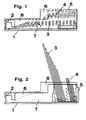
- FIG. 1 shows an embodiment of the bridge bid box according to the invention. It consists of the bottom 1 and the lid 2 and is in the closed state, ie, suitable for transport.
- the bidding card sets ie the bidding card set 3 of the long bidding cards and the bidding card set 4 of the short bidding cards, are located in the compartments of the card setting part 5.
- the cover 2 there is an inclined plane or as curved edge formed space delimiter 6, and in the bottom 1 a web-shaped card manifold 7 is provided. Room delimiter 6 and card manifold 7 interact in the manner - as FIG. 1 illustrates - that when the bridge bid box is closed, the bid card sets 3 and 4 are slightly curved and secured against slipping.
- the bridge bid box shown in Fig. 2 is in the ready-to-play position, ie the card setting part 5 with the bid card sets 3 and 4 located therein is folded up so that the bid cards are accessible to the bridge players.
- the walls between the individual compartments of the card setting part 5 are of different heights, as a result of which the bidding card packs have a different inclination.
- the resulting greater distance between the bid card sets allows easier access to the bid cards.
- the card setting part 5 is - as will be made clear later - secured by the cover 2 or by an access recess at the right end of the cover 2.
- the side parts of base 1 and cover 2 have a greater height at the right end than at the left end.
- FIG. 3 shows the bottom 1 of the bridge bid box as a one-line part.
- the L-shaped recess 8 (which is present on both sides) can be seen, into which the card setting part 5 can be hung.
- the bottom 1 has pins 9 (on both sides), on which the cover 2 is hung.
- the card manifold 7 can also be seen in FIG. 3. It can be formed in one piece or consist of several disks arranged side by side, as illustrated in FIG. 4.
- FIGS. 5 and 6 show different views of the floor 1 according to FIGS. 3 and 4.
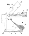
- Figures 7,8,9 and 10 show different views of the cover 2 as an individual part.
- the room delimiters 6 can be clearly seen in FIG.
- the cover 2 has an L-shaped recess 10 on both sides, into which the pins 9 (FIGS. 3 - 6) of the base 1 engage in the completed bridge bid box.
- the space limiter (s) 6 consist of one or more disks arranged next to one another.
- Fig. 8 the existing at the right end of the cover 2 access recess 11 can be seen.
- knob-shaped thickenings 12 On the side parts of the lid 2 there are knob-shaped thickenings 12 which serve to form a clamp between the bottom 1 and lid 2 when the bridge bid box is closed.
- FIGS. 11 to 15 show different views of the card setting part 5.
- the card setting part 5 has the compartments 13 and 14 for receiving the long and short bid card set.
- the card adjustment part 5 is provided with pins 15, with which it is suspended in the L-shaped recess 8 (FIG. 3) of the base 1.
- 17 to 24 illustrate in several steps how the bridge bid box is brought from the closed (for transport) state to the ready-to-play state.
- the bid card sets 3 and 4 in the card setting part 5 are still in a slightly raised position on the left.
- the cover 2 has already been moved to the left so that it can be opened.
- the cover is fully opened.
- the card setting part 5 can now - after being guided in the cutout 8 - be moved to the right.
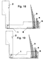
- Fig. 19 shows the card setting part 5 in the fully folded state.
- Fig. 19 shows the card setting part 5 in the fully folded state.
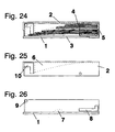
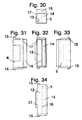
- FIG. 20 shows another exemplary embodiment of the bridge bid box according to the invention. In principle, it corresponds to the bridge bid box according to FIG. 1. The difference between the bridge bid box in FIGS. 1 and 24 is that in the embodiment according to FIG.
- the side parts of base 1 and cover 24 also has the bottom 1, the cover 2 and the card setting part 5 in which the bidding card sets 3 and 4 are arranged.
- 25 shows the cover 2 as an individual part. In principle, it corresponds to the cover 2 in FIG. 7.
- the space limiter 6 can also be seen.
- the cover 2 is likewise provided with an L-shaped recess 10 on both sides at the left end.
- Fig. 26 shows the bottom 1 as a single part. It corresponds in principle to base 1 in FIG. 3.
- This base 1 is likewise provided with pins 9 at the left end and has L-shaped cutouts 8 at the right end.
- the card manifold 7 can also be seen. It can be formed in one piece or consist of several disks arranged side by side.
- Fig. 27 shows the cover 2 as an individual part. In principle, it corresponds to the cover 2 in FIG. 8. Parts of the space limiter 6, the access recess 10 and the thickenings 12 can be seen.
- FIGS. 27 and 29 show different views of the cover 2 according to FIGS. 25 and 27. In principle they correspond to FIGS. 9 and 10.
- Figures 30 to 34 show different views of the card setting part 5. They correspond in principle to Figures 11 to 15. The same parts are provided with the same reference numerals. 30 that the rear wall 17 is lower than the middle wall 16 of the card setting part 5.
- FIG. 27 shows a top view of the floor 1 according to FIG. 26.
- FIGS. 28 and 29 show different views of the floor 1 according to FIGS. 26 and 27.
- FIGS. 38 to 47 it is illustrated in several successive steps how the bridge bid box is brought from the closed (for transport) state to the ready-to-play state.
- the bridge bid box shown in FIG. 38 the bidding card sets 3 and 4 in the card setting part 5 are still in a horizontal position.
- the cover 2 has already been moved to the left so that it can be raised.
- the cover 2 has been raised so that it can be opened. 40, the cover 2 is already half-opened.
- FIG. 41 the cover 2 is completely opened.
- the card setting part 5 can now - guided in the recess 8 - moved to the right and folded up.
- Fig. 42 shows the card setting part 5 in the folded-up state.
- Fig. 43 shows the card setting part 5 in the fully folded state.
- the card setting part 5 - guided in the recess 8 - is shifted to the left. As a result, it has reached its end position.
- Fig. 45 illustrates that the lid 2 is then folded down.
- the lid 2 is again in the horizontal. It is completely lowered onto the floor 1.
- the cover 2 - guided in the recess 10 - is shifted to the right into its end position.
- the card setting part 5 and the card sets 3 and 4 are supported by the edge of the access recess 11 (Fig. 27).
Landscapes
- Engineering & Computer Science (AREA)
- Multimedia (AREA)
- Details Of Rigid Or Semi-Rigid Containers (AREA)
- Packaging Of Annular Or Rod-Shaped Articles, Wearing Apparel, Cassettes, Or The Like (AREA)
- Cartons (AREA)
- Closures For Containers (AREA)
- Vehicle Step Arrangements And Article Storage (AREA)
Description
Die Verhinderung des Herausrutschens der Biet-Karten aus dem Karten-Einstellteil in den Boden entscheidet über die Funktionsfähigkeit der Bridge-Bid-Box, insbesondere dann, wenn die Biet-Karten auch bei geschlossener Bridge-Bid-Box in jeder Lage im Karten-Einstellteil verbleiben sollen.
- Fig. 1
- die Seitenansicht einer Ausführungsform der erfindungsgemäßen Bridge-Bid-Box in geschlossenem Zustand,
- Fig. 2
- die Bridge-Bid-Box gemäß Fig. 1 mit Biet-Karten in spielbereitem Zustand,
- Fig. 3
- der Boden der Bridge-Bid-Box gemäß Fig.1 in Seitenansicht,
- Fig. 4
- die Draufsicht auf die Oberseite des Bodens gemäß Fig.3,
- Fig. 5
- die Draufsicht auf die linke Stirnseite des Bodens gemäß Fig. 4,
- Fig. 6
- die Draufsicht auf die rechte Stirnseite des Bodens gemäß Fig. 4,
- Fig. 7
- die Seitenansicht des Deckels der Bridge-Bid-Box gemäß Fig.1,
- Fig. 8
- die Draufsicht auf die Oberseite des Deckels gemäß Fig.7,
- Fig. 9
- die Draufsicht auf die linke Stirnseite des Deckels gemäß den Figuren 7 und 8,
- Fig. 10
- die Draufsicht auf die rechte Stirnseite des Deckels gemäß den Figuren 7 und 8,
- Fig. 11
- die Seitenansicht des Karten-Einstellteils der Bridge-Bid-Box gemäß Fig. 1,
- Fig. 12
- die Draufsicht auf die linke Seite des Karten-Einstellteils gemäß Fig. 11,
- Fig. 13
- die Draufsicht auf die Oberseite des Karten-Einstellteils gemäß Fig. 11,
- Fig. 14
- die Draufsicht auf die rechte Seite des Karten-Einstellteils gemäß Fig. 11,
- Fig. 15
- die Draufsicht auf den Boden des Karten-Einstellteils gemäß Fig. 11,
- Fig. 16
- die Bridge-Bid-Box gemäß Fig.1 mit halb geöffnetem Deckel,
- Fig. 17
- die Bridge-Bid-Box gemäß Fig. 16 mit geöffnetem Deckel und teils ausgeklapptem Karten-Einstellteil,
- Fig. 18
- die Bridge-Bid-Box gemäß Fig. 16 mit geöffnetem Deckel und ausgeklapptem Karten-Einstellteil,
- Fig. 19
- die Bridge-Bid-Box gemäß Fig. 16 mit geöffnetem Deckel und im Boden arretiertem Karten-Einstellteil,
- Fig. 20
- die Bridge.Bid-Box gemäß Fig. 19 während des Schließens des Deckels,
- Fig. 21
- die Bridge-Bid-Box gemäß Fig. 19 nach dem Schließen des Deckels,
- Fig. 22
- die Bridge-Bid-Box gemäß Fig. 19 nachdem der Deckel auf den Boden heruntergeklappt ist,
- Fig. 23
- die Bridge-Bid- Box gemäß Fig. 19 nachdem der Deckel über dem Boden an das Karten-Einstellteil heransgeschoben worden ist,
- Fig. 24
- die Seitenansicht einer anderen Ausführungsform der erfindungsgemäßen Bridge-Bid-Box in geschlossenem Zustand,
- Fig. 25
- der Deckel der Bridge-Bid-Box gemäß Fig. 24,
- Fig. 26
- der Boden der Bridge-Bid-Box gemäß Fig. 24,
- Fig. 27
- die Draufsicht auf die Oberseite des Deckels gemäß Fig. 25,
- Fig. 28
- die Draufsicht auf die linke Strinseite des Deckels gemäß Fig. 27, ,
- Fig. 29
- die Draufsicht auf die rechte Stirnseite des Deckels gemäß Fig. 27,
- Fig. 30
- die Seitenansicht des Karten-Einstellteils für die Bridge-Bid-Box gemäß Fig. 24,
- Fig. 31
- die Draufsicht auf die linke Seite des Karten-Einstellteils gemäß Fig. 30,
- Fig. 32
- die Draufsicht auf die Oberseite des Karten-Einstellteils gemäß Fig. 30,
- Fig. 33
- die Draufsicht auf die rechte Seite des Karten Einstellteils gemäß Fig. 30,
- Fig. 34
- die Draufsicht auf den Boden des Karten-Einstellteils gemäß Fig.30,
- Fig. 35
- die Daufsicht auf den Boden der Bridge-Bid-Box gemäß Fig. 24,
- Fig. 36
- die Draufsicht auf die linke Seite des Bodens gemäß Fig. 35,
- Fig. 37
- die Draufsicht auf die rechte Seite des Bodens gemäß Fig. 35,
- Fig. 38
- die Bridge-Bid-Box gemäß Fig. 24,bei welcher der Deckel gegenüber dem Boden nach links verschoben worden ist,
- Fig. 39
- die Bridge-Bid-Box gemäß Fig. 38, bei welcher der Deckel vertikal angehoben worden ist,
- Fig. 40
- die Bridge-Bid-Box gemäß Fig. 38 mit halb aufgeklapptem Deckel,
- Fig. 41
- die Bridge-Bid-Box gemäß Fig. 38 mit vollständig aufgeklapptem Deckel,
- Fig. 42
- die Bridge-Bid-Box gemäß Fig. 38 mit halb hochgeklapptem Karten-Einstellteil,
- Fig. 43
- die Bridge-Bid-Box gemäß Fig. 38 mit hochgeklapptem Karten-Einstellteil,
- Fig. 44
- die Bridge-Bid-Box gemäß Fig. 43 mit nach links verschobenem Karten-Einstellteil,
- Fig. 45
- die Bridge-Bid-Box gemäß Fig. 44 mit teils eingeklapptem Deckel,
- Fig. 46
- die Bridge-Bid-Box gemäß Fig. 44 mit geschlossenem Deckel und
- Fig. 47
- die Bridge-Bid-Box gemäß Fig. 44 mit nach rechts an das Karten-Einstellteil angeschobenem Deckel.
Die Biet-Kartensätze, d.h. der Biet-Kartensatz 3 der langen Biet-Karten und der Biet-Kartensatz 4 der kurzen Biet-Karten, befinden sich in den Fächern des Karten-Einstellteils 5. Im Deckel 2 ist ein als schräge Ebene bzw. als gekrümmte Kante ausgebildeter Raumbegrenzer 6 , und im Boden 1 ist ein stegförmig ausgebildeter Kartenkrümmer 7 vorgesehen. Raumbegrenzer 6 und Kartenkrümmer 7 wirken in der Weise zusammen - wie Fig. 1 verdeutlicht - daß bei geschlossener Bridge-Bid-Box die Biet-Kartensätze 3 und 4 leicht gekrümmt und gegen Verrutschen gesichert sind.
Bei dem in den Figuren 1 und 2 gezeigten Ausführungsbeispiel der Bridge-Bid-Box weisen die Seitenteile von Boden 1 und Deckel 2 am rechten Ende eine größere Höhe auf als am linken Ende.
Fig. 3 zeigt den Boden 1 der Bridge-Bid-Box als Einzeilteil. Es ist die (beidseitig vorhandene) L-förmige Aussparung 8 zu erkennen, in welche das Karten-Einstellteil 5 eingehängt werden kann. Am linken Ende besitzt der Boden 1 (beidseitig vorhandene) Stifte 9, an welchen der Deckel 2 eingehängt wird. In Fig. 3 ist auch der Kartenkrümmer 7 zu erkennen. Er kann einstückig ausgebildet sein oder aus mehreren nebeneinander angeordneten Scheiben bestehen, wie Fig. 4 verdeutlicht.
Die Figuren 5 und 6 zeigen verschiedene Ansichten des Bodens 1 gemäß den Figuren 3 und 4.
Die Figuren 7,8,9 und 10 zeigen verschiedene Ansichten des Deckels 2 als Einzelteil. In Fig.7 sind die Raumbegrenzer 6 deutlich zu erkennen. Am linken Ende weist der Deckel 2 beidseitig eine L-förmige Aussparung 10 auf, in welche bei der vervollständigten Bridge-Bid-Box die Stifte 9 ( Fig. 3 - 6) des Bodens 1 eingreifen. Wie aus den Figuren 8,9 und 10 zu erkennen ist, besteht/bestehen der/die Raumbegrenzer 6 aus einer oder mehreren nebeneinander angeordneten Scheiben.
In Fig. 8 ist die am rechten Ende des Deckels 2 vorhandene Zugriffsaussparung 11 zu erkennen. An den Seitenteilen des Deckels 2 sind noppenförmige Verdickungen 12 angeordnet, welche zur Bildung einer Klemmung zwischen Boden 1 und Deckel 2 bei geschlossener Bridge-Bid-Box dienen.
Die Figuren 11 bis 15 zeigen verschiedene Ansichten des Karten-Einstellteils 5.Wie aus Fig. 11 zu erkennen ist,besitzt das Karten-Einstellteil 5 die Fächer 13 und 14 zur Aufnahme des langen und kurzen Biet-Kartensatzes. In der unteren linken Ecke ist das Karten-Einstellteil 5 mit Stiften 15 versehen, mit denen es in die L-förmige Aussparung 8 (Fig. 3 ) des Bodens 1 eingehängt ist.
Anhand der Figuren 17 bis 24 ist in mehreren Schritten verdeutlicht, wie die Bridge-Bid-Box aus dem geschlossenen (für den Transport ) Zustand in den spielbereiten Zustand gebracht wird.
Bei der in Fig. 17 gezeigten Bridge-Bid-Box befinden sich die Biet-Kartensätze 3 und 4 im Karten-Einstellteil 5 noch in einer links leicht angehobenen Lage. Der Deckel 2 ist bereits nach links verschoben worden, so daß er aufgeklappt werden kann.
Bei der Darstellung der Bridge-Bid-Box in Fig. 18 ist der Deckel vollständig aufgeklappt. Das Karten-Einstellteil 5 kann nun - nachdem es in der Aussparung 8 geführt -nach rechts verschoben worden ist hochgeklappt werden.
Fig. 19 zeigt das Karten-Einstellteil 5 in vollständig hochgeklapptem Zustand. In Fig. 20 ist das Karten-Einstellteil 5 - in der Aussparung 8 geführt- nach links verschoben. Dadurch hat es seine Endstellung erreicht.
Fig. 21 verdeutlicht, daß danach der Deckel 2 heruntergeklappt wird. In Fig. 22 befindet sich der Deckel 2 wieder in der Horizontalen. In Fig. 23 ist der Deckel 2 vollständig auf den Boden 1 abgesenkt. In Fig. 24 ist der Deckel 2 - in der Aussparung 10 geführt - nach rechts in seine Endstellung verschoben. Dabei werden das Karten-Einstellteil 5 und die Biet-Kartensätze 3 und 4 von der Kante der Zugriffsaussparung 11 (Fig. 8 ) gestützt.
Fig. 24 zeigt ein anderes Ausführungsbeispiel der erfindungsgemäßen Bridge-Bid-Box. Sie entspricht im Prinzip der Bridge-Bid-Box gemäß Fig. 1. Der Unterschied zwischen der Bridge-Bid-Box in Fig. 1 und Fig. 24 besteht darin, daß bei der Ausführungsform gemäß Fig. 24 die Seitenteile von Boden 1 und Deckel 2 die gleiche Höhe aufweisen.Die Bridge-Bid-Box gemäß Fig. 24 besteht ebenfalls aus dem Boden 1, dem Deckel 2 und dem Karten-Einstellteil 5, in dem die Biet-Kartensätze 3 und 4 angeordnet sind.
Fig. 25 zeigt den Deckel 2 als Einzelteil. Er entspricht im Prinzip dem Deckel 2 in Fig. 7. Der Raumbegrenzer 6 ist ebenfalls zu erkennen. Der Deckel 2 ist bei dieser Ausführungsform ebenfalls am linken Ende beidseitig mit einer L-förmigen Aussparung 10 versehen.
Fig. 26 zeigt den Boden 1 als Einzelteil. Er entspricht im Prinzip dem Boden 1 in Fig. 3. Dieser Boden 1 ist ebenfalls am linken Ende mit Stiften 9 versehen und weist am rechten Ende L-förmige Aussparungen 8 auf. Außerdem ist der Kartenkrümmer 7 zu erkennen. Er kann einstückig ausgebildet sein oder aus mehreren nebeneinander angeordneten Scheiben bestehen.
Die Figuren 27 und 29 zeigen verschiedene Ansichten des Deckels 2 gemäß Fig. 25 und 27. Sie entsprechen im Prinzip den Figuren 9 und 10.
Die Figuren 30 bis 34 zeigen verschiedene Ansichten des Karten-Einstellteils 5. Sie entsprechen im Prinzip den Figuren 11 bis 15. Die gleichen Teile sind mit den gleichen Bezugszeichen versehen. In Fig. 30 ist deutlich zu erkennen, daß die hintere Wand 17 niedriger als die mittlere Wand 16 des Karten-Einstellteils 5 ist.
Anhand der Figuren 38 bis 47 ist in mehreren aufeinander folgenden Schritten verdeutlicht, wie die Bridge-Bid-Box aus dem geschlossenen ( für den Transport ) Zustand in den spielbereiten Zustand gebracht wird.
Bei der in Fig. 38 gezeigten Bridge-Bid-Box befinden sich die Biet-Kartensätze 3 und 4 im Karten-Einstellteil 5 noch in horizontaler Lage. Der Deckel 2 ist bereist nach links verschoben worden, so daß er angehoben werden kann.
Bei der Darstellung in Fig. 39 ist der Deckel 2 angehoben worden, so daß er aufgeklappt werden kann. In Fig. 40 ist der Deckel 2 bereits halb aufgeklappt.
Bei der Darstellung in Fig. 41 ist der Deckel 2 vollständig aufgeklappt. Das Karten-Einstellteil 5 kann nun - in der Aussparung 8 geführt - nach rechts verschoben und hochgeklappt werden.
Fig. 43 zeigt das Karten-Einstellteil 5 in vollständig hochgeklapptem Zustand.
In Fig. 44 ist das Karten-Einstellteil 5 - in der Aussparung 8 geführt - nach links verschoben. Dadurch hat es seine Endstellung erreicht.
Fig.45 verdeutlicht, daß danach der Deckel 2 heruntergeklappt wird.In Fig.46 befindet sich der Deckel 2 wieder in der Horizontalen.Er ist vollständig auf den Boden 1 abgesenkt. In Fig. 47 ist der ist der Deckel 2 - in der Aussparung 10 geführt- nach rechts in seine Endstellung verschoben. Dabei werden das Karten-Einstellteil 5 und die Kartensätze 3 und 4 von der Kante der Zugriffsaussparung 11 (Fig.27) gestützt.
Claims (7)
- Bridge-Bid-Box, enthaltend die folgenden Merkmale:gekennzeichnet durch folgende Merkmale:einen flachen kastenförmigen, an einer Stirnseite offenen Boden (1),einen flachen kastenförmigen, an einer Stirnseite offenen Deckel (2),an der offenen Stirnseite des Bodens (1) ist das Karten-Einstellteil (5) schwenkbar befestigt.der Deckel (2) ist an der dem Karten-Einstellteil (5) zugewandten Stirnseite mit einer Zugriffsaussparung (11) versehen,an der offenen stirnseite des Bodens (1) ist ein Karten-Einstellteil (5) vorhanden,Boden (1) und Deckel (2) sind an der geschlossenen Stirnseite schwenkbar miteinander verbunden,
- Bridge-Bid-Box nach Anspruch 1, dadurch gekennzeichnet, daß die Seitenwände von Boden (1) und Deckel (2) am offenen Ende eine größere Höhe als am geschlossenen Ende aufweisen.
- Bridge-Bid-Box nach den Ansprüchen 1 und 2, dadurch gekennzeichnet, daß auf der Innenfläche des Bodens (1) ein sich in Querrrichtung erstreckender stegförmiger Kartenkrümmer (7) angeordnet ist.
- Bridge-Bid-Box nach den Ansprüchen 1 bis 3, dadurch gekennzeichnet, daß auf der Innenfläche des Deckels (2) wenigstens ein, eine schräge Ebene bildender Raumbegrenzer (6) angeordnet ist.
- Bridge-Bid-Box nach den Ansprüchen 1 bis 4, dadurch gekennzeichnet, daß am geschlossenen Ende des Deckels (2) beidseitig L-förmige Aussparungen (8) vorgesehen sind, welche mit Stiften (9) an den Seitenteilen des Bodens (1) zusammenwirken.
- Bridge-Bid-Box nach den Ansprüchen 1 bis 5, dadurch gekennzeichnet, daß das offene Ende des Bodens (1) beidseitig mit L-förmigen Aussparungen (10) versehen ist, in welche das Karten-Einstellteil (5) mittels Stiften (15) eingehängt ist.
- Bridge-Bid-Box nach den Ansprüchen 1 bis 6, dadurch gekennzeichnet, daß das Karten-Einstellteil (5) aus einem in zwei Fächer (13,14) unterteilten Kasten besteht, dessen Wände (16,17) unterschiedlich hoch sind.
Applications Claiming Priority (2)
| Application Number | Priority Date | Filing Date | Title |
|---|---|---|---|
| DE19758316 | 1997-12-31 | ||
| DE19758316 | 1997-12-31 |
Publications (3)
| Publication Number | Publication Date |
|---|---|
| EP0927564A2 EP0927564A2 (de) | 1999-07-07 |
| EP0927564A3 EP0927564A3 (de) | 2000-05-24 |
| EP0927564B1 true EP0927564B1 (de) | 2004-09-22 |
Family
ID=7853633
Family Applications (1)
| Application Number | Title | Priority Date | Filing Date |
|---|---|---|---|
| EP98124673A Expired - Lifetime EP0927564B1 (de) | 1997-12-31 | 1998-12-24 | Bridge - Bid - Box |
Country Status (3)
| Country | Link |
|---|---|
| EP (1) | EP0927564B1 (de) |
| AT (1) | ATE276812T1 (de) |
| DE (1) | DE59811991D1 (de) |
Families Citing this family (2)
| Publication number | Priority date | Publication date | Assignee | Title |
|---|---|---|---|---|
| DE10047987C1 (de) | 2000-09-28 | 2002-01-24 | Helmut Gschweng | Aufbewahrungsbox für Gegenstände aller Art, insbesondere für Spielkarten |
| FR3053599A1 (fr) * | 2016-07-11 | 2018-01-12 | Christian Jean Felix Antoine Lafon | Dispositif permettant de retenir les cartons d'encheres, utilises pour jouer au bridge, dans la boite a encheres si l'on tombe cette boite |
Family Cites Families (2)
| Publication number | Priority date | Publication date | Assignee | Title |
|---|---|---|---|---|
| SE8301124L (sv) * | 1983-03-01 | 1984-09-02 | Duplikat Dbt Ab | For forvaring av kort avsedd behallare |
| DE4438040C2 (de) * | 1994-10-25 | 2001-10-04 | Helmut Gschweng | Bridge-Quick-Box |
-
1998
- 1998-12-24 AT AT98124673T patent/ATE276812T1/de not_active IP Right Cessation
- 1998-12-24 EP EP98124673A patent/EP0927564B1/de not_active Expired - Lifetime
- 1998-12-24 DE DE59811991T patent/DE59811991D1/de not_active Expired - Fee Related
Also Published As
| Publication number | Publication date |
|---|---|
| EP0927564A3 (de) | 2000-05-24 |
| DE59811991D1 (de) | 2004-10-28 |
| ATE276812T1 (de) | 2004-10-15 |
| EP0927564A2 (de) | 1999-07-07 |
Similar Documents
| Publication | Publication Date | Title |
|---|---|---|
| EP0253102A1 (de) | Aufbewahrungsbehälter für Magnetbandkassetten | |
| EP0453724A2 (de) | Mehrteiliger Aufnahmebehälter | |
| DE9012845U1 (de) | Flaschenkasten | |
| DE69715599T2 (de) | Verbesserte einsetzbare schale | |
| DE202007010660U1 (de) | Aufbewahrungs-Einrichtung, bevorzugter eine Aufbewahrungs-Einrichtung für Disks | |
| DE60115711T2 (de) | Sichere abgabevorrichtung | |
| EP0927564B1 (de) | Bridge - Bid - Box | |
| DE1810003A1 (de) | Plattenspielergehaeuse | |
| DE3724828C1 (de) | Sichtlagerkasten | |
| DE202008007945U1 (de) | Vorrichtung zum Lagern und/oder Transportieren von Bremsen, insbesondere von Nutzfahrzeugscheibenbremsen, sowie Schale einer solchen Vorrichtung | |
| DE4315054A1 (de) | Greifvorrichtung eines Müllsammelfahrzeuges zum Entleeren von Müllbehältern | |
| DE9306650U1 (de) | Kassette zur Aufbewahrung mehrerer plattenförmiger Datenträger o.dgl. | |
| EP0023977A1 (de) | Vorrichtung zum Aufbewahren von Gegenständen, insbesondere Kassetten, mit einem bandförmigen Aufzeichnungsträger | |
| WO1998018113A1 (de) | Anzeigekassette für auswechselbare informationsträger mit einem mittels zumindest einem klappdeckel verschliessbaren trägergehäuse | |
| DE3887584T2 (de) | Behältnisse, insbesondere Karteibehältnisse. | |
| DE2003378A1 (de) | Speicher fuer Filmblattmagazine | |
| DE4438040C2 (de) | Bridge-Quick-Box | |
| DE2345934C3 (de) | Vorrichtung zum Verkauf von Reißverschlüssen oder von ähnlichen Verkaufseinheiten | |
| DE7402445U (de) | Kunststoff-Box zur Aufnahme von Tonbandkassetten | |
| DE19619372C2 (de) | Magazin zum Aufbewahren flacher Gegenstände | |
| EP0976667B1 (de) | Vorrichtung zur Aufnahme mehrerer Gegenstände in übereinanderliegenden Ebenen | |
| DE20206745U1 (de) | Behälter mit Zigaretten aufnehmendem Innenraum | |
| EP1227492A1 (de) | Aufbewahrungsbehälter für Kassetten | |
| DE29501163U1 (de) | Kartenspiel | |
| EP0029507A1 (de) | Vorrichtung zum Einbringen von Flaschen in Kartons |
Legal Events
| Date | Code | Title | Description |
|---|---|---|---|
| PUAI | Public reference made under article 153(3) epc to a published international application that has entered the european phase |
Free format text: ORIGINAL CODE: 0009012 |
|
| AK | Designated contracting states |
Kind code of ref document: A2 Designated state(s): AT BE DE DK FI FR GB IE IT LU MC NL SE |
|
| AX | Request for extension of the european patent |
Free format text: AL;LT;LV;MK;RO;SI |
|
| PUAL | Search report despatched |
Free format text: ORIGINAL CODE: 0009013 |
|
| AK | Designated contracting states |
Kind code of ref document: A3 Designated state(s): AT BE CH CY DE DK ES FI FR GB GR IE IT LI LU MC NL PT SE |
|
| AX | Request for extension of the european patent |
Free format text: AL;LT;LV;MK;RO;SI |
|
| RIC1 | Information provided on ipc code assigned before grant |
Free format text: 7A 63F 1/10 A, 7B 42F 7/14 B |
|
| 17P | Request for examination filed |
Effective date: 20001115 |
|
| AKX | Designation fees paid |
Free format text: AT BE DE DK FI FR GB IE IT LU MC NL SE |
|
| GRAP | Despatch of communication of intention to grant a patent |
Free format text: ORIGINAL CODE: EPIDOSNIGR1 |
|
| GRAS | Grant fee paid |
Free format text: ORIGINAL CODE: EPIDOSNIGR3 |
|
| GRAA | (expected) grant |
Free format text: ORIGINAL CODE: 0009210 |
|
| AK | Designated contracting states |
Kind code of ref document: B1 Designated state(s): AT BE DE DK FI FR GB IE IT LU MC NL SE |
|
| PG25 | Lapsed in a contracting state [announced via postgrant information from national office to epo] |
Ref country code: NL Free format text: LAPSE BECAUSE OF FAILURE TO SUBMIT A TRANSLATION OF THE DESCRIPTION OR TO PAY THE FEE WITHIN THE PRESCRIBED TIME-LIMIT Effective date: 20040922 Ref country code: IT Free format text: LAPSE BECAUSE OF FAILURE TO SUBMIT A TRANSLATION OF THE DESCRIPTION OR TO PAY THE FEE WITHIN THE PRE;WARNING: LAPSES OF ITALIAN PATENTS WITH EFFECTIVE DATE BEFORE 2007 MAY HAVE OCCURRED AT ANY TIME BEFORE 2007. THE CORRECT EFFECTIVE DATE MAY BE DIFFERENT FROM THE ONE RECORDED.SCRIBED TIME-LIMIT Effective date: 20040922 Ref country code: IE Free format text: LAPSE BECAUSE OF FAILURE TO SUBMIT A TRANSLATION OF THE DESCRIPTION OR TO PAY THE FEE WITHIN THE PRESCRIBED TIME-LIMIT Effective date: 20040922 Ref country code: FR Free format text: LAPSE BECAUSE OF FAILURE TO SUBMIT A TRANSLATION OF THE DESCRIPTION OR TO PAY THE FEE WITHIN THE PRESCRIBED TIME-LIMIT Effective date: 20040922 Ref country code: FI Free format text: LAPSE BECAUSE OF FAILURE TO SUBMIT A TRANSLATION OF THE DESCRIPTION OR TO PAY THE FEE WITHIN THE PRESCRIBED TIME-LIMIT Effective date: 20040922 |
|
| REG | Reference to a national code |
Ref country code: GB Ref legal event code: FG4D Free format text: NOT ENGLISH |
|
| REG | Reference to a national code |
Ref country code: IE Ref legal event code: FG4D Free format text: GERMAN |
|
| REF | Corresponds to: |
Ref document number: 59811991 Country of ref document: DE Date of ref document: 20041028 Kind code of ref document: P |
|
| PG25 | Lapsed in a contracting state [announced via postgrant information from national office to epo] |
Ref country code: SE Free format text: LAPSE BECAUSE OF FAILURE TO SUBMIT A TRANSLATION OF THE DESCRIPTION OR TO PAY THE FEE WITHIN THE PRESCRIBED TIME-LIMIT Effective date: 20041222 Ref country code: DK Free format text: LAPSE BECAUSE OF FAILURE TO SUBMIT A TRANSLATION OF THE DESCRIPTION OR TO PAY THE FEE WITHIN THE PRESCRIBED TIME-LIMIT Effective date: 20041222 |
|
| PG25 | Lapsed in a contracting state [announced via postgrant information from national office to epo] |
Ref country code: LU Free format text: LAPSE BECAUSE OF NON-PAYMENT OF DUE FEES Effective date: 20041224 Ref country code: GB Free format text: LAPSE BECAUSE OF NON-PAYMENT OF DUE FEES Effective date: 20041224 Ref country code: AT Free format text: LAPSE BECAUSE OF NON-PAYMENT OF DUE FEES Effective date: 20041224 |
|
| PG25 | Lapsed in a contracting state [announced via postgrant information from national office to epo] |
Ref country code: MC Free format text: LAPSE BECAUSE OF NON-PAYMENT OF DUE FEES Effective date: 20041231 Ref country code: BE Free format text: LAPSE BECAUSE OF NON-PAYMENT OF DUE FEES Effective date: 20041231 |
|
| GBT | Gb: translation of ep patent filed (gb section 77(6)(a)/1977) |
Effective date: 20050116 |
|
| NLV1 | Nl: lapsed or annulled due to failure to fulfill the requirements of art. 29p and 29m of the patents act | ||
| REG | Reference to a national code |
Ref country code: IE Ref legal event code: FD4D |
|
| BERE | Be: lapsed |
Owner name: *GSCHWENG HELMUT Effective date: 20041231 |
|
| PLBE | No opposition filed within time limit |
Free format text: ORIGINAL CODE: 0009261 |
|
| STAA | Information on the status of an ep patent application or granted ep patent |
Free format text: STATUS: NO OPPOSITION FILED WITHIN TIME LIMIT |
|
| GBPC | Gb: european patent ceased through non-payment of renewal fee |
Effective date: 20041224 |
|
| 26N | No opposition filed |
Effective date: 20050623 |
|
| EN | Fr: translation not filed | ||
| PGFP | Annual fee paid to national office [announced via postgrant information from national office to epo] |
Ref country code: DE Payment date: 20060626 Year of fee payment: 8 |
|
| PG25 | Lapsed in a contracting state [announced via postgrant information from national office to epo] |
Ref country code: DE Free format text: LAPSE BECAUSE OF NON-PAYMENT OF DUE FEES Effective date: 20070703 |
|
| BERE | Be: lapsed |
Owner name: *GSCHWENG HELMUT Effective date: 20041231 |