EP0927645B1 - Vorrichtung und Verfahren zum Bearbeiten einer Tiefdruckform - Google Patents
Vorrichtung und Verfahren zum Bearbeiten einer Tiefdruckform Download PDFInfo
- Publication number
- EP0927645B1 EP0927645B1 EP19980115589 EP98115589A EP0927645B1 EP 0927645 B1 EP0927645 B1 EP 0927645B1 EP 19980115589 EP19980115589 EP 19980115589 EP 98115589 A EP98115589 A EP 98115589A EP 0927645 B1 EP0927645 B1 EP 0927645B1
- Authority
- EP
- European Patent Office
- Prior art keywords
- rotary tool
- oscillation
- transducer
- rotary
- steel blade
- Prior art date
- Legal status (The legal status is an assumption and is not a legal conclusion. Google has not performed a legal analysis and makes no representation as to the accuracy of the status listed.)
- Expired - Lifetime
Links
Images

Classifications
-
- B—PERFORMING OPERATIONS; TRANSPORTING
- B41—PRINTING; LINING MACHINES; TYPEWRITERS; STAMPS
- B41N—PRINTING PLATES OR FOILS; MATERIALS FOR SURFACES USED IN PRINTING MACHINES FOR PRINTING, INKING, DAMPING, OR THE LIKE; PREPARING SUCH SURFACES FOR USE AND CONSERVING THEM
- B41N3/00—Preparing for use and conserving printing surfaces
Definitions
- the invention relates to a device for processing a gravure form according to the preamble of claim 1.
- the invention further relates to a method for Processing of a gravure form according to the generic term of Claim 11.
- Document EP-A-0 808 723 discloses both Device according to the preamble of claim 1 as well as a method according to the preamble of claim 11.
- the gravure forms used in gravure printing are usually designed as gravure cylinders.
- Such a gravure cylinder usually has one made of copper, zinc or a corresponding alloy existing, cylindrical metal layer in whose Outer layer depressions are engraved, which the ink is determined to be included. After this It will be engraved based on the metals used relatively soft cylinder surface with a usually electroplated, more wear resistant Metal layer coated, which is usually made of chrome consists. After the printing process is complete, the Gravure cylinder for a next engraving process prepared by removing at least the chrome layer becomes.
- An object of the invention is a method to remove the more wear-resistant metal layer Intaglio form, in particular an intaglio cylinder create that is reliable and inexpensive.
- Die Subclaims 2 to 10 relate to further advantageous embodiments of the inventive Contraption.
- Die Subclaims 12 to 15 relate to further, advantageous embodiments of the inventive Process.
- a turning tool is preferably used as the turning tool extensively used a cutting edge.
- the turning tool is at least while cutting through the converter a high-frequency vibration, the exciting vibration preferably between 1 kHz and 100 kHz.
- the method according to the invention has the advantage on that the chrome layer of the gravure cylinder on can be removed very gently.
- the accruing Chips which are chrome and zinc respectively Zinc alloy are recyclable. It fall no polluted waste water.
- the turned rotogravure cylinders a homogeneous Surface structure in which a new engraving or to which a new metal layer is applied can.
- the swinging of the turning steel or the turning steel cutting edge has a particularly advantageous effect when turning off one Gravure cylinder, because that is the wasted material in the form of relatively short chips.
- An essential one The advantage is that the relatively short chips fall off the cylinder in such a way that the turned one Surface is not damaged. Would when turning long chips are generated, there is a risk that they touch and damage the turned surface.
- Such damage to the surface of a Gravure cylinder represents a considerable financial damage because for a four-color print a set of four gravure cylinders with the same Diameter is required. If the damage to the Surface would be removed by turning, so would have to also the surfaces of the remaining three Gravure cylinders are turned off.
- the swinging of the turning steel also has an advantageous effect on the service life of the turning steel cutting edge.
- the device according to the invention or the The method according to the invention is also advantageous suitable to process gravure cylinders, which one Outer layer made of copper or a copper alloy have which with a chrome layer or other hard layer is covered. Also at such gravure cylinders causes the vibrating Turning steel relatively short chips, so no danger there is damage to the turned off chips Cause surface.
- the chips are also advantageously recyclable.
- the controllable converter is preferably a configured piezoelectric transducer, whereby also other transducers generating a vibration are suitable are, for example, a hydraulic or mechanical excited converter.
- the converter is preferably aligned in such a way Holding device arranged that the one longitudinal direction having turning tool to a cross, in particular vibration perpendicular to the longitudinal direction is stimulable.
- An additional converter could also be arranged such that an in Vibration running in the longitudinal direction of the turning tool can be generated on this.
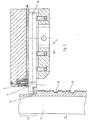
- Fig. 1 shows a longitudinal section through a Holding device 3, which has a recess for receiving of the turning tool 1 designed as turning tool 1 having.
- the turning tool 1 is screwed 3b against the opposite side of the screws 3b Bracket 3a pressed and thereby held firmly.
- the Turning tool 1 is to the right of the one labeled 3c Place over the entire length section firmly on the bracket 3a, whereas the to the turning tool 1 facing surface of the bracket 3a left of Position 3c backs away so that there is a gap between the Bracket 3a and the turning tool 1 are not in contact, and the turning tool 1 can swing freely.
- Point 3c longitudinal section could, however, also Have recesses formed such that the Turning tool 1 only firmly on the partial length sections Bracket 3a rests, these partial length sections in a preferred embodiment opposite the Screws 3b arranged, and with respect to the longitudinal direction 1c dimensioned approximately the same size as the screws 3b are designed.
- the screws 3b and the partial length sections are such arranged in the longitudinal direction 1c that the Turning steel cutting edge 1a of turning tool 1 with as much as possible large vibration amplitude is excitable, what is particularly achievable in that the screws 3b or the partial length sections on those Are arranged at which the turning tool 1 in Longitudinal direction 1c has a vibration node.
- a piezoelectric transducer 5 is in the holder 3a arranged and has an operative connection to the turning tool 1 on, in order to 1c in the direction of vibration Transfer alternating force and thereby to a To stimulate vibration.
- the converter 5 comprises several plate-shaped, stacked one on top of the other piezoelectric elements 5e.
- the piezoelectric Elements 5e are on both sides of a clamping part 5c, 5d limited, these clamping parts 5c, 5d by a Screw 5f held together or mutually are led.
- the clamping part 5c is over a plate 5b connected with an adjusting screw 5a.
- bracket 3a In the bracket 3a is a threaded bore for receiving the Adjustment screw 5a is provided so that the mutual Position of converter 5 and bracket 3a by turning the Adjusting screw 5a is adjustable in the direction 1c.
- the Piezoelectric elements 5e are about electrical Conductors 7a, 7b, which are components of the electrical Cable 7 are, with a not shown Control device electrically connected.
- the turning tool 1 has a cutting edge 1a at its tip.
- the Turning steel has one by its longitudinal expansion determined longitudinal direction 1b.
- a sensor for detecting can be on the holding device 3 the vibration amplitude of the turning tool 1 or its turning steel cutting edge 1a arranged his.
- a piezoelectric Element 5e of the transducer 5 for measuring the Vibration amplitude used in this piezoelectric element 5e compared to the rest piezoelectric elements 5e electrically isolated arranged as a sensor, the sensor value derived with the help of an electrical cable and a Amplifier is supplied.
- the piezoelectric elements 5e experience this one Linear expansion or a reduction in length, which is transmitted from the converter 5 to the turning tool 1.
- the converter 5 generated alternating force in a perpendicular to Longitudinal direction 1b in the direction 1c Turned steel 1 initiated.
- This alternating force could also in another, transverse to the longitudinal direction 1b Direction initiated.
- the holding device 3 can also several, in the same or in different Direction acting on the clamped turning tool 1 Have converter 5.
- the Holding device several holders 3a for holding each of a turning tool 1, at least one the rotary steels 1 vibrated by the converter 5 can be.
- the drive frequency of the converter 5 selected such that the turning tool 1 with its resonance frequency or one Harmonics of it is excited.
- either Drive frequency of the converter 5 selected accordingly be, or the turning tool 1 can accordingly be designed, for example by its Dimensioning or by an appropriate Choice of material or elasticity of the turning tool.
- the resonance frequency of the turning tool 1 is due to the Arrangement of the screws spaced in the longitudinal direction 1b 3b can be influenced.
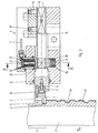
- Fig. 2 shows a section of a cross section a gravure cylinder 20 with a base body 21, which is made of a suitable material such as Steel, aluminum or plastic.
- Base body 21 On this Base body 21 is a first in a known manner Metallic layer 22 applied, for example made of copper, zinc, a copper alloy or one Zinc alloy is made.
- This first metallic layer 22 is coated with a more wear-resistant layer 23, which, for example, made of chrome or another Hard material layer exists.
- This more wear-resistant Layer 23 has depressions on its surface Recording ink on. After a completed one Printing process, the more wear-resistant layer 23 to be removed again to insert a new print pattern into the Engrave the surface.
- FIG. 2 shows a cross section through the gravure cylinder 20 represents, the conveying direction F of the turning tool 1 with respect to the view according to FIG. 2 vertically upwards.
- the rotating gravure cylinder 20 leads with respect 2 is an upward view Rotary motion so that the machined Circumferential section 24 of the gravure cylinder already is turned and a cylindrical surface having.
- the holding device 3 shown in FIG. 2 is identical to that shown in Figure 1 Holding device 3, which is why only the most important parts Reference numerals are provided.
- the converter 5 generates one high-frequency alternating force on the turning tool 1, so that this vibrates in the direction of movement 1c becomes. This direction of movement 1c runs perpendicular to Rotation axis of the gravure cylinder 20 and perpendicular to Direction of movement F of the holding device 3 or parallel to the cutting direction of the Turning tool.
- the converter 5 could, however, also be used in this way the holding device 3 may be arranged that the Turning tool 1 is vibrated, the Movement direction 1c in a vertical to that according to FIG. 2 viewing plane runs.
- This Direction of movement 1c would thus be parallel to the axis of rotation of the gravure cylinder 20, or parallel to Direction of movement F of the holding device 3, or perpendicular to the cutting direction of the Turning steel cutting edge 1a run.
- the frequency the alternating force is in the range between 1 kHz and 100 kHz, being a stimulating electrical signal for example a sine signal, a square wave signal or also an asymmetrical signal like a sawtooth Signal can be used.
- the converter 5 could also be arranged such that the turning tool 1 to a in the direction of the Longitudinal direction 1b moving vibration is excited.
- the Gravure cylinder 20 moved in a direction of movement F. be, wherein the holding device 3 is fixed or one opposite to the direction of movement F. Movement.
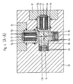
- a tool holder 3 comprises one piezoelectric transducer 5 with piezoelectric Elements 5e, clamping part 5d, plate 5b, screw 5f and Guide sleeve 5g.
- the converter 5 is opposite Spring and support body 8 arranged, which one Plurality of stacked spring elements 8a includes and a clamping part 8b, which on the Turning tool 1 rests.
- the clamping body 1d is over the screws 3b releasably firmly with the holding device 3rd connected and via the clamping parts 5d, 8b and elastic support 3c swingably mounted.
- the Converter 5 is capable of turning tool 1 in Movement direction 1c to vibrate.
- the turning tool 1 multi-part and consists of two essential parts, the clamping body 1d and one fastened the front of the clamping body 1d Cutting tool holder 1i with cutting tool 1a.
- the Turning tool holder 1i is over a screw 1e as well as a sleeve 1f with the clamping body 1d connected, with an additional bolt 1g as Protection against rotation is provided.
- Between the Clamping body 1d and the turning tool holder 1i could an additional, in the longitudinal direction 1b of the Clamping body 1d acting piezoelectric transducer 5 be arranged to the turning steel cutting edge 1a also in to a vibration running in the longitudinal direction 1b offset.
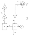
- Fig. 5 shows an electronic circuit diagram for Control of a piezoelectric transducer 5. From one Control device 10b with display device 10c is turned on Specified setpoint, which via an electrical Line 10i predefined for a control device 10d becomes. This controls via a downstream Preamplifier 10e and a power amplifier 10f via the electrical line 7b, the converter 5, whereby this is vibrated. The vibration of the Transducer 5 or the vibration of the turning tool 1 is detected with a sensor and via the electrical line 7c and the preamplifier 10a of the control device 10b fed.
- the control device 10b can for example are controlled such that the turning tool 1 or the turning steel cutting edge 1a is as large as possible Vibration amplitude in which the excitation frequency is varied in this way, e.g. in the frequency range between 1 kHz and 100 kHz until a maximum vibration amplitude occurs. Via converter 5 or an additional one The sensor is also the vibration behavior of the Gravure cylinder 20 measurable.
- the control device 10b can be operated in such a way that when a Predeterminable vibration value at least one of the following machining parameters: speed of the cylinder, Feed speed of the turning tool 1, Vibration amplitude of the turning steel cutting edge 1a, Vibration frequency of the turning steel cutting edge 1a changed is to the vibration of the gravure cylinder 20 too Reduce. Be via a control signal line 10g Control signals, for example, to the rotary drive of the Cylinder forwarded to its speed too change.
- control loop shown in Fig. 5 is with a A variety of control methods can be controlled such that the machined rotogravure cylinders one if possible has a uniform surface.
- a piezoelectric element 5e of the transducer 5 can used to control the vibration of the To detect turning tool 1, from this Vibration signal the vibration of the Gravure cylinder 20 can be derived. So with With the help of the transducer 5 the vibration of the Gravure cylinder 20 measurable. Are in the Tool holding device 3 several transducers 5 arranged as shown in Fig. 4, the corresponding vibration in the direction 1c, 1h, and if necessary also in direction 1b.
Landscapes
- Manufacture Or Reproduction Of Printing Formes (AREA)
Description
- Fig. 1
- einen Schnitt durch eine Werkzeughaltevorrichtung mit eingespanntem Drehstahl;
- Fig. 2
- einen an einem Tiefdruckzylinder angreifenden, in der Werkzeughaltevorrichtung gemäss Fig. 1 eingespannten Drehstahl;
- Fig. 3
- einen Schnitt durch ein weiteres Ausführungsbeispiel einer Werkzeughaltevorrichtung mit eingespanntem Drehwerkzeug;
- Fig. 4
- einen Schnitt entlang der Linie A-A gemäss Fig. 3;
- Fig. 5
- ein Schaltbild einer elektronischen Ansteuervorrichtung.
Claims (16)
- Vorrichtung zum Bearbeiten einer Tiefdruckform (20), insbesondere eines Tiefdruckzylinders, dadurch gekennzeichnet, daß sie eine Haltevorrichtung (3) für ein Drehwerkzeug (1) zum Bearbeiten der Tiefdruckform (20), sowie zumindest einen ansteuerbaren Wandler (5), insbesondere einen piezoelektrischen Wandler, zum Erzeugen einer auf das Drehwerkzeug (1) wirkenden Schwingung umfaßt.
- Vorrichtung nach Anspruch 1, dadurch gekennzeichnet, dass der Wandler (5) starr an das Drehwerkzeug (1) ankoppelbar ausgestaltet ist.
- Vorrichtung nach einem der vorhergehenden Ansprüche, dadurch gekennzeichnet, dass der Wandler (5) derart ausgerichtet in der Haltevorrichtung (3) angeordnet ist, dass das eine Längsrichtung (1b) aufweisende Drehwerkzeug (1) zu einer quer, insbesondere senkrecht zur Längsrichtung (1b) verlaufenden Schwingung (1c) anregbar ist.
- Vorrichtung nach Anspruch 3, dadurch gekennzeichnet, dass zwei Wandler (5) derart ausgerichtet an der Haltevorrichtung (3) angeordnet sind, dass zwei orthogonal ausgerichtete, senkrecht zur Längsrichtung (1b) verlaufende Schwingungsanteile (1c,1d) auf das Drehwerkzeug (1) erzeugbar sind.
- Vorrichtung nach einem der vorhergehenden Ansprüche, dadurch gekennzeichnet, dass ein Wandler (5) derart ausgerichtet in der Haltevorrichtung (3) angeordnet ist, dass das eine Längsrichtung (1b) aufweisende Drehwerkzeug (1) zu einer in Längsrichtung (1b) verlaufenden Schwingung anregbar ist.
- Vorrichtung nach einem der vorhergehenden Ansprüche, dadurch gekennzeichnet, dass das Drehwerkzeug (1) derart bezüglich der vom Wandler (5) erzeugten Schwingungsfrequenz angepasst ausgestaltet und/oder in der Haltevorrichtung (3) angeordnet ist, dass das Drehwerkzeug (1) in Eigenfrequenz schwingend anregbar ist.
- Vorrichtung nach einem der vorhergehenden Ansprüche, dadurch gekennzeichnet, dass an der Haltevorrichtung (3) ein Sensor zum Erfassen der Schwingungsamplitude des Drehwerkzeuges (1) bzw. dessen Drehstahlschneide (1a) angeordnet ist, und dass der Sensor insbesondere als ein Piezoelement ausgebildet ist, insbesondere als ein Element des piezoelektrischen Wandlers (5).
- Vorrichtung nach einem der vorhergehenden Ansprüche, dadurch gekennzeichnet, dass der Wandler (5) mit einer Frequenz zwischen 1 kHz und 100 kHz betreibbar ist.
- Vorrichtung nach einem der vorhergehenden Ansprüche, dadurch gekennzeichnet, dass der Wert der Schwingungsamplitude des Drehwerkzeuges (1) bzw. dessen Drehstahlschneide (1a) einer Regelvorrichtung (10b) zugeführt ist, und die Regelvorrichtung (19b) derart zum Ansteuern des Wandlers (5) ausgestaltet ist, dass das Drehwerkzeug (1) bzw. dessen Drehstahlschneide (1a) eine vorgebbare, insbesondere maximale Schwingungsamplitude aufweist.
- Vorrichtung nach einem der vorhergehenden Ansprüche, dadurch gekennzeichnet, dass das Drehwerkzeug (1) mehrteilig ausgestaltet ist, umfassend einen in der Haltevorrichtung (3) befestigbaren Einspannkörper (1d) sowie einen am Einspannkörper (1d) befestigten Drehstahlschneidenhalter (1i) mit Drehstahlschneide (1a).
- Verfahren zum Bearbeiten einer Tiefdruckform (20), insbesondere eines Tiefdruckzylinders, welche zumindest eine erste metallische Schicht (22) sowie eine diese überdeckende, bezüglich der ersten metallischen Schicht (22) verschleissfestere Schicht (23) aufweist, dadurch gekennzeichnet, daß zumindest die verschleissfestere Schicht (23) mit einem Drehwerkzeug (1) abgedreht wird, welches von einem Wandler (5) in Schwingung versetzt wird.
- Verfahren nach Anspruch 11, dadurch gekennzeichnet, dass das Drehwerkzeug (1) mit einer Frequenz zwischen 1 kHz und 100 kHz beaufschlagt wird und die Frequenz insbesondere derart gewählt wird, dass die Drehstahlschneide (1a) des Drehwerkzeuges (1) eine maximale Schwingungsamplitude aufweist.
- Verfahren nach einem der Ansprüche 11 oder 12, dadurch gekennzeichnet, dass mit demselben Drehwerkzeug (1) gleichzeitig die verschleissfestere Schicht (23) und ein Teilbereich der darunter liegenden, ersten metallischen Schicht (22) abgedreht wird.
- Verfahren nach einem der Ansprüche 11 bis 13, dadurch gekennzeichnet, dass die verschleissfestere Schicht (23) aus Chrom oder einem Metalloxid besteht, und die erste metallische Schicht (22) aus Zink oder einer Zinklegierung oder aus Kupfer oder einer Kupferlegierung besteht.
- Verfahren nach einem der Ansprüche 11 bis 14, dadurch gekennzeichnet, dass die Schwingung des Tiefdruckzylinders (20) gemessen wird, insbesondere über den Wandler (5), und dass beim Übersteigen eines vorgebbaren Schwingungswertes zumindest einer der folgenden Bearbeitungsparameter: Drehzahl des Zylinders, Vorschubgeschwindigkeit des Drehwerkzeuges (1), Schwingungsamplitude der Drehstahlschneide (1a), Schwingungsfrequenz der Drehstahlschneide (1a) verändert wird, um die Schwingung des Tiefdruckzylinders (20) zu vermindern.
- Bearbeitungsanlage für eine Tiefdruckform (20), insbesondere einen Tiefdruckzylinder, umfassend eine Vorrichtung nach einem der Ansprüche 1 bis 10 oder betrieben mit einem Verfahren nach einem der Ansprüche 11 bis 15.
Priority Applications (1)
| Application Number | Priority Date | Filing Date | Title |
|---|---|---|---|
| EP19980115589 EP0927645B1 (de) | 1998-01-05 | 1998-08-19 | Vorrichtung und Verfahren zum Bearbeiten einer Tiefdruckform |
Applications Claiming Priority (3)
| Application Number | Priority Date | Filing Date | Title |
|---|---|---|---|
| EP98810001 | 1998-01-05 | ||
| EP98810001A EP0927646A1 (de) | 1998-01-05 | 1998-01-05 | Vorrichtung und Verfahren zum Bearbeiten einer Tiefdruckform |
| EP19980115589 EP0927645B1 (de) | 1998-01-05 | 1998-08-19 | Vorrichtung und Verfahren zum Bearbeiten einer Tiefdruckform |
Publications (2)
| Publication Number | Publication Date |
|---|---|
| EP0927645A1 EP0927645A1 (de) | 1999-07-07 |
| EP0927645B1 true EP0927645B1 (de) | 2002-10-30 |
Family
ID=26149549
Family Applications (1)
| Application Number | Title | Priority Date | Filing Date |
|---|---|---|---|
| EP19980115589 Expired - Lifetime EP0927645B1 (de) | 1998-01-05 | 1998-08-19 | Vorrichtung und Verfahren zum Bearbeiten einer Tiefdruckform |
Country Status (1)
| Country | Link |
|---|---|
| EP (1) | EP0927645B1 (de) |
Family Cites Families (2)
| Publication number | Priority date | Publication date | Assignee | Title |
|---|---|---|---|---|
| US4924713A (en) * | 1988-03-14 | 1990-05-15 | Elco Co., Ltd. | Transducer to detect force which is applied to machine tool when machining workpiece and its attaching structure |
| ATE188918T1 (de) * | 1996-05-23 | 2000-02-15 | Valerio Rosa | Verfahren und maschine zum entfernen von gravuren und chromschichten von tiefdruckzylindern |
-
1998
- 1998-08-19 EP EP19980115589 patent/EP0927645B1/de not_active Expired - Lifetime
Also Published As
| Publication number | Publication date |
|---|---|
| EP0927645A1 (de) | 1999-07-07 |
Similar Documents
| Publication | Publication Date | Title |
|---|---|---|
| DE4223645C2 (de) | Verfahren zum Vibrations-Bearbeiten eines Werkstücks und Vibrations-Schneidvorrichtung | |
| EP1140474B1 (de) | Verfahren zum konstanthalten der mittleren spaltbreite zwischen einer sonotrode eines ultraschall-systems und einem als gegenfläche ausgebildeten werkzeug einer ultraschall-schneideinrichtung | |
| EP1849569B2 (de) | Vorrichtung zum Bearbeiten von Werkstücken mittels Ultraschall sowie Verfahren zum Betreiben einer derartigen Vorrichtung | |
| EP1954442B1 (de) | Verfahren zur reduktion von schwingungen eines maschinenelements und/oder eines werkstücks | |
| DE3002510A1 (de) | Ultraschallbearbeitungsverfahren und -vorrichtung | |
| DE69511983T2 (de) | Verfahren und Vorrichtung zum Funkenerodieren | |
| EP0321590A2 (de) | Verfahren und Vorrichtung zum Herstellen eines eine scharfe Schneidkante aufweisenden Stanzwerkzeugs | |
| DE2117305C3 (de) | Werkzeughalter zur Schwingzerspanung mit einem einen Schneidkörper aufweisenden Schneidwerkzeug | |
| DE2257102A1 (de) | Verfahren zur beseitigung des vom farbwerk uebertragenen farbueberschusses auf tiefdruckzylindern mittels rakel | |
| DE1959852A1 (de) | Fluessigkeitszufuehrung fuer Elektroerosionsmaschinen | |
| EP0927645B1 (de) | Vorrichtung und Verfahren zum Bearbeiten einer Tiefdruckform | |
| DE3102044A1 (de) | Verfahren und vorrichtung zum elektroerosiven bearbeiten eines werkstueckes | |
| EP3072621A1 (de) | Drahtführung zur führung einer drahtelektrode beim drahterodieren | |
| WO2003047861B1 (de) | Vorrichtung zum ausrichten eines aufzuges | |
| DE3813176A1 (de) | Ultraschallschwingungs-bearbeitungsvorrichtung | |
| DE4213013C2 (de) | Vorrichtung zum Erzeugen eines zu druckenden Musters auf einer Druckform-Hülse | |
| EP0927646A1 (de) | Vorrichtung und Verfahren zum Bearbeiten einer Tiefdruckform | |
| EP0389871A2 (de) | Vorrichtung zum Steuern einer automatischen Gussputzmaschine | |
| DE2317213C3 (de) | Rakelvorrichtung für eine Rotationsdruckmaschine | |
| DE20019097U1 (de) | Stanzvorrichtung | |
| DE60007083T2 (de) | Elektroden-klemmvorrichtung für funkenerosionsbearbeitungsvorrichtung | |
| DE1502578A1 (de) | Verfahren und Vorrichtung fuer die Feinbearbeitung von Werkstuecken | |
| EP1150842B1 (de) | Gravierorgan | |
| DE3100342A1 (de) | Verfahren und vorrichtung zum bearbeiten eines werkstueckes | |
| DE69407589T2 (de) | Einstellbares schneidwerkzeug für schälbearbeitung |
Legal Events
| Date | Code | Title | Description |
|---|---|---|---|
| PUAI | Public reference made under article 153(3) epc to a published international application that has entered the european phase |
Free format text: ORIGINAL CODE: 0009012 |
|
| AK | Designated contracting states |
Kind code of ref document: A1 Designated state(s): DE ES FR GB IT NL |
|
| AX | Request for extension of the european patent |
Free format text: AL;LT;LV;MK;RO;SI |
|
| 17P | Request for examination filed |
Effective date: 19991104 |
|
| AKX | Designation fees paid |
Free format text: DE ES FR GB IT NL |
|
| GRAG | Despatch of communication of intention to grant |
Free format text: ORIGINAL CODE: EPIDOS AGRA |
|
| 17Q | First examination report despatched |
Effective date: 20020204 |
|
| GRAG | Despatch of communication of intention to grant |
Free format text: ORIGINAL CODE: EPIDOS AGRA |
|
| GRAH | Despatch of communication of intention to grant a patent |
Free format text: ORIGINAL CODE: EPIDOS IGRA |
|
| GRAH | Despatch of communication of intention to grant a patent |
Free format text: ORIGINAL CODE: EPIDOS IGRA |
|
| GRAA | (expected) grant |
Free format text: ORIGINAL CODE: 0009210 |
|
| AK | Designated contracting states |
Kind code of ref document: B1 Designated state(s): DE ES FR GB IT NL |
|
| PG25 | Lapsed in a contracting state [announced via postgrant information from national office to epo] |
Ref country code: NL Free format text: LAPSE BECAUSE OF FAILURE TO SUBMIT A TRANSLATION OF THE DESCRIPTION OR TO PAY THE FEE WITHIN THE PRESCRIBED TIME-LIMIT Effective date: 20021030 |
|
| REG | Reference to a national code |
Ref country code: GB Ref legal event code: FG4D Free format text: NOT ENGLISH |
|
| REF | Corresponds to: |
Ref document number: 59806108 Country of ref document: DE Date of ref document: 20021205 |
|
| GBT | Gb: translation of ep patent filed (gb section 77(6)(a)/1977) |
Effective date: 20030304 |
|
| NLV1 | Nl: lapsed or annulled due to failure to fulfill the requirements of art. 29p and 29m of the patents act | ||
| REG | Reference to a national code |
Ref country code: ES Ref legal event code: FG2A Ref document number: 2185097 Country of ref document: ES Kind code of ref document: T3 |
|
| ET | Fr: translation filed | ||
| PG25 | Lapsed in a contracting state [announced via postgrant information from national office to epo] |
Ref country code: GB Free format text: LAPSE BECAUSE OF NON-PAYMENT OF DUE FEES Effective date: 20030819 |
|
| PG25 | Lapsed in a contracting state [announced via postgrant information from national office to epo] |
Ref country code: ES Free format text: LAPSE BECAUSE OF NON-PAYMENT OF DUE FEES Effective date: 20030820 |
|
| PLBE | No opposition filed within time limit |
Free format text: ORIGINAL CODE: 0009261 |
|
| STAA | Information on the status of an ep patent application or granted ep patent |
Free format text: STATUS: NO OPPOSITION FILED WITHIN TIME LIMIT |
|
| 26N | No opposition filed |
Effective date: 20030731 |
|
| PG25 | Lapsed in a contracting state [announced via postgrant information from national office to epo] |
Ref country code: DE Free format text: LAPSE BECAUSE OF NON-PAYMENT OF DUE FEES Effective date: 20040302 |
|
| GBPC | Gb: european patent ceased through non-payment of renewal fee |
Effective date: 20030819 |
|
| PG25 | Lapsed in a contracting state [announced via postgrant information from national office to epo] |
Ref country code: FR Free format text: LAPSE BECAUSE OF NON-PAYMENT OF DUE FEES Effective date: 20040430 |
|
| REG | Reference to a national code |
Ref country code: FR Ref legal event code: ST |
|
| REG | Reference to a national code |
Ref country code: ES Ref legal event code: FD2A Effective date: 20030820 |
|
| PG25 | Lapsed in a contracting state [announced via postgrant information from national office to epo] |
Ref country code: IT Free format text: LAPSE BECAUSE OF NON-PAYMENT OF DUE FEES Effective date: 20050819 |