EP0927792A2 - Elément de pavage - Google Patents
Elément de pavage Download PDFInfo
- Publication number
- EP0927792A2 EP0927792A2 EP98124686A EP98124686A EP0927792A2 EP 0927792 A2 EP0927792 A2 EP 0927792A2 EP 98124686 A EP98124686 A EP 98124686A EP 98124686 A EP98124686 A EP 98124686A EP 0927792 A2 EP0927792 A2 EP 0927792A2
- Authority
- EP
- European Patent Office
- Prior art keywords
- paving stone
- paving
- spacer
- stone element
- stone
- Prior art date
- Legal status (The legal status is an assumption and is not a legal conclusion. Google has not performed a legal analysis and makes no representation as to the accuracy of the status listed.)
- Granted
Links
- 239000004575 stone Substances 0.000 claims abstract description 154
- 125000006850 spacer group Chemical group 0.000 claims abstract description 60
- 230000015572 biosynthetic process Effects 0.000 claims description 6
- 238000005755 formation reaction Methods 0.000 claims description 6
- 239000000463 material Substances 0.000 claims description 5
- 238000013461 design Methods 0.000 abstract description 9
- 238000006073 displacement reaction Methods 0.000 abstract 1
- 239000002131 composite material Substances 0.000 description 9
- 238000003780 insertion Methods 0.000 description 6
- 230000037431 insertion Effects 0.000 description 6
- 239000011505 plaster Substances 0.000 description 4
- 230000000694 effects Effects 0.000 description 3
- 230000000007 visual effect Effects 0.000 description 3
- 230000003287 optical effect Effects 0.000 description 2
- 241001290864 Schoenoplectus Species 0.000 description 1
- 230000005540 biological transmission Effects 0.000 description 1
- 150000001875 compounds Chemical class 0.000 description 1
- 238000012937 correction Methods 0.000 description 1
- 230000001419 dependent effect Effects 0.000 description 1
- 238000011161 development Methods 0.000 description 1
- 238000010586 diagram Methods 0.000 description 1
- 125000000524 functional group Chemical group 0.000 description 1
- 238000009434 installation Methods 0.000 description 1
- 238000012986 modification Methods 0.000 description 1
- 230000004048 modification Effects 0.000 description 1
- 238000012549 training Methods 0.000 description 1
- 230000007704 transition Effects 0.000 description 1
Images


Classifications
-
- E—FIXED CONSTRUCTIONS
- E01—CONSTRUCTION OF ROADS, RAILWAYS, OR BRIDGES
- E01C—CONSTRUCTION OF, OR SURFACES FOR, ROADS, SPORTS GROUNDS, OR THE LIKE; MACHINES OR AUXILIARY TOOLS FOR CONSTRUCTION OR REPAIR
- E01C5/00—Pavings made of prefabricated single units
-
- E—FIXED CONSTRUCTIONS
- E01—CONSTRUCTION OF ROADS, RAILWAYS, OR BRIDGES
- E01C—CONSTRUCTION OF, OR SURFACES FOR, ROADS, SPORTS GROUNDS, OR THE LIKE; MACHINES OR AUXILIARY TOOLS FOR CONSTRUCTION OR REPAIR
- E01C5/00—Pavings made of prefabricated single units
- E01C5/005—Individual couplings or spacer elements for joining the prefabricated units
- E01C5/006—Individual spacer elements
-
- E—FIXED CONSTRUCTIONS
- E01—CONSTRUCTION OF ROADS, RAILWAYS, OR BRIDGES
- E01C—CONSTRUCTION OF, OR SURFACES FOR, ROADS, SPORTS GROUNDS, OR THE LIKE; MACHINES OR AUXILIARY TOOLS FOR CONSTRUCTION OR REPAIR
- E01C2201/00—Paving elements
- E01C2201/02—Paving elements having fixed spacing features
-
- E—FIXED CONSTRUCTIONS
- E01—CONSTRUCTION OF ROADS, RAILWAYS, OR BRIDGES
- E01C—CONSTRUCTION OF, OR SURFACES FOR, ROADS, SPORTS GROUNDS, OR THE LIKE; MACHINES OR AUXILIARY TOOLS FOR CONSTRUCTION OR REPAIR
- E01C2201/00—Paving elements
- E01C2201/04—Paving elements consisting of natural stones and a binder
-
- E—FIXED CONSTRUCTIONS
- E01—CONSTRUCTION OF ROADS, RAILWAYS, OR BRIDGES
- E01C—CONSTRUCTION OF, OR SURFACES FOR, ROADS, SPORTS GROUNDS, OR THE LIKE; MACHINES OR AUXILIARY TOOLS FOR CONSTRUCTION OR REPAIR
- E01C2201/00—Paving elements
- E01C2201/16—Elements joined together
Definitions
- the present invention relates to a paving stone element, especially made of concrete.
- Paving surfaces made of single paving stones are known and are often used in a demanding design environment their scale-forming quality of flat, unorganized Preferred coverings.
- the present invention is therefore based on the object to create a paving stone element that is high Can absorb loads, a high degree of design Offers quality and freedom, economically producible and is easy to lay.
- the paving stone element designed according to the invention is designed so that several paving stone elements form-fitting can be laid to a composite plaster.
- the individual paving stone elements grip without continuous joints in one another, so that a particularly effective Association or association and thus a high level of security against shifting, twisting or tilting of the individual Paving stone elements are created in the paving structure.
- Paving stone element all adjacent rectangular areas with their entire contact edges together. To this There is a way between adjacent rectangular areas no offset. In a further embodiment of the invention however, there are individual adjacent rectangular areas only with a part of their entire contact edges to each other, so that between adjacent rectangular areas a corresponding offset results. All embodiments the invention is in any case common that it have at least one vertical inner edge that formed by two side surfaces of the paving stone element is, these side surfaces each to a cuboid Belong section, the bottom or top of which forms a corresponding rectangular area.
- the individual is adjacent Rectangular areas with only part of their total contact edges one embodiment is preferred, in which three rectangular areas arranged in a row are present, the middle of which is laterally offset is.
- the rectangular areas arranged independently of each other and thus cuboid single paving stone elements available are preferably in the material of the visible surface of the Paving stone element several less by dummy joints Deep, separate shapes in the form of paving stone heads trained who along with the dummy joints Cover the base of the element.
- the visible surface of the paving stone element several paving stone heads separated by dummy joints made of natural stone or the like used together with the dummy joints cover the base of the element.
- the paving stone element spacers on its side faces to a Provide joints and / or with spacers from others Elements to interlock. That way a joint between adjacent elements when laying ensured.
- These spacers are useful ledge-shaped and extend over the entire Height of the side surface or only over part of it, to give the impression when viewed from above to convey a continuous joint.
- the paving stone element according to the invention expediently a wedge-shaped in plan trained spacers in the area of an inner vertical, especially two side surfaces without spacers limiting edge.
- This element which is wedge-shaped in plan, takes over at the same time spacer function in two directions and is used for Guiding the stone to be inserted when inserted into his exact position.
- the paving stone element preferably has on it opposite the wedge-shaped spacer Side surface at least one spacer, the interlocked with the spacer of an adjacent element.
- the above insertion is in one embodiment the invention additionally facilitated if the Side surface of the wedge-shaped spacer parallel to one side flank of a spacer on the opposite Paving stone element side surface runs.
- Pushing in is made even easier when the other Side flank of the spacer on the opposite Side surface at a very flat angle to the Stone element side surface runs.
- This other side flank can be used in addition to the stone guide when inserting to serve.
- the invention further relates to an edge compensation stone for Paving stone elements of the type described above, the has the shape of a cuboid, which matches the shape of the remaining due to the installed paving stone elements Gap is adjusted, in particular the shape of the Offset of the central cuboid of the paving stone element emerging gap.
- a leveling stone can have spacers arranged on its side surfaces exhibit.
- Figure 1 is a schematic diagram of a paving stone element 1 shown with a U-shaped plan, which consists of five Squares 2 is formed. The contiguous squares lie together with their entire contact edges. The entire Element 1 is e.g. made of one piece of concrete manufactured.
- Figure 2 shows in principle how several paving stone elements 1 form-fitting to a composite plaster can be relocated.
- the individual paving stone elements 1 interlock without continuous joints, so that a particularly effective association and thus a high level of security against shifting, twisting or tilting of the individual Paving stone elements 1 is created in the paving structure.
- Figure 3 shows the - not absolutely necessary here shown example but chosen - design of Paving stone element 1 in terms of design. in the Material of its visible surface (top) are several through False joints 3 shallow depth, separate shapes of paving stone heads 4, which together with the Dummy joints 3 cover the base of element 1.
- FIG. 2 The surface interacting as shown in FIG. 2 appears with a visible surface design as shown in FIG. 3 visually like a conventional paving with individual paving stones, as shown in Figure 4.
- FIGs 5 to 8 are some of the possible others Embodiments of paving stone elements 5 to 8 are shown. These consist of four T-shaped squares 2 (paving stone element 5, Figure 5), four S-shaped arranged squares 2 (paving stone element 6, FIG. 6), four L-shaped squares 2 (paving stone element 7, Figure 7) or three L-shaped squares 2 (paving stone element 8, Figure 8). The resulting one associated functional group is in the respective figures also shown.
- the visual impression at Training with paving stone heads 4 corresponds in all Cases that of Figure 4.
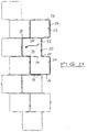
- FIG a paving stone element 9 shown.
- Their floor plan consists of three squares 10 arranged in a row, 11, 12, whose middle square 11 is offset to the side is. For example, the offset is half Edge length of the squares 11, 12, 13.
- the visible surface of the Paving stone element 9 is as described above with formations designed in the form of paving stone heads 4.
- spacers There are two types of spacers, namely running vertically on the outer sides of the outer cuboids 10, 12 arranged, approximately element-high first spacers 13 with half-cylinder profile and the vertically the connecting lines of the outer cuboids 10, 12 with the middle cuboid 11 in the range by the offset of middle cuboid 11 running along the gap arranged second spacer 14 with fillet profile.
- first Edge leveling stones 16 which have the shape of an entire cuboid 10, 11, 12 and second edge compensation stones 15 that shape the resulting from the offset of the central cuboid 11 Gap, usually a third to a half stone 10, 11, 12.
- These two types of leveling stones too 15, 16 have spacers on their outer edges on, which are not shown here.
- the paving stone element 9 described is not only particularly advantageous with regard to its resilience, but also offers appealing laying options, as Figures 11, 15, 16 and 17 show.
- the paving stone elements must be cut on those running in the direction of travel Plaster edges are not required. Only the edge compensation stones 15 are to be installed. For joints perpendicular to Direction of travel - for example when changing the direction of feed - Instead of the edge compensation stone 16 Edge adjustment with relatively little cutting effort (by cutting off the stone sections 17) as Figure 18 shows.
- diagonal laying can be a special one visual appeal can be achieved. In particular place-like Win situations, junction and intersection areas through generous diagonal laying. Technically always complex and often problematic in terms of design You can change the laying direction Minimize diagonal laying, as shown in Figure 17.
- the usable material is not limited to concrete.
- the paving heads can be made of natural stone, e.g. is embedded in concrete.
- Figure 19 shows a further embodiment of a paving stone element in two perspective views.
- the paving stone element 20 is set composed of three cuboids 21, 22, 23, each in the upper Area are separated from each other by a dummy joint 24.
- the cuboids 21, 22, 23 each correspond in plan to one Rectangle, where all three rectangles are the same size.
- the cuboids 21 and 23 are arranged in a row while the intermediate cuboid 22 is offset accordingly is arranged so that the cuboids 21 and 22 and 22 and 23 touch only over part of their side surfaces.
- the paving stone element 20 is provided with spacers 25, 26, 27 provided, which are in the vertical direction on the corresponding Extend side faces and not to the top pass through the paving stone element, so that of above the impression of a circumferential joint is created.
- the Spacer 25 is wedge-shaped in plan and in the area of an inner edge of the Paving stone element arranged. This is best in FIG. 20 shows a top view of the paving stone element of Figure 19 shows. How to remove Figure 20 there are four internal edges on which a wedge-shaped spacer 25 is arranged is. The ones in the figure are arranged above two spacers inclined opposite to the lower ones two spacers.
- Spacer 27 On the side surfaces of the two outer cuboids 21 and 23 is a single one Spacer 27 is arranged, which is approximately semicircular in plan is trained. Such a spacer 27 is also on the side surface pointing to the left in FIG. 20 of the central cuboid 23 available.
- the one in figure 20 up and down side faces of the two outer cuboids 21 and 23 each carry three spacers 26, which have an approximately triangular shape in plan.
- the left flank 28 of the spacers exactly the same inclination as the associated spacer 25 on the opposite side surface of the cuboid 21 or 23, while the slope of the right flank of the Spacer 25 corresponds to the next but one cuboid.
- FIG 21 shows a top view of one of paving stone elements 19 and 20 composite association, specifically the insertion of a paving stone element 20 is represented in the existing association.
- This Paving stone element 20 is shown with thicker lines. It can be seen that here the inserted paving stone element 20 with the upper edge of his in the figure middle cuboid against the wedge-shaped spacer 25 of the neighboring paving stone element, so that this the distance between the paving stone elements in the figure is set up and to the left. The the same effect occurs with the wedge-shaped spacers on the two inner ones on the left in the figure Edge of the paving stone element 20 to be inserted are.
- the two spacers 26 on the in the figure interlock the lower side surface of the element 20 to be inserted themselves with corresponding spacers 26 of the neighboring one Paving stone element.
- the side surfaces of the spacers are preferably which forcefully pulls out the paving stone element should prevent from his position formed parallel to the side surface of one in plan wedge-shaped spacer in the area of an inner Edge of the paving stone element is arranged.
- This spacer which is wedge-shaped in plan, acts as a spacer towards the two stone sides, between which it is arranged, and enables one if necessary slight twisting of two stones against each other without the spacer effect is thereby lost.
- they are preferably not power transmission serving side surfaces of the spacers, which are non-positive pulling out the paving stone element to prevent its position, at a flat angle, in particular less than 30 ° to the stone side surface educated.
Landscapes
- Engineering & Computer Science (AREA)
- Architecture (AREA)
- Civil Engineering (AREA)
- Structural Engineering (AREA)
- Road Paving Structures (AREA)
- Preparation Of Clay, And Manufacture Of Mixtures Containing Clay Or Cement (AREA)
- Curing Cements, Concrete, And Artificial Stone (AREA)
Applications Claiming Priority (2)
| Application Number | Priority Date | Filing Date | Title |
|---|---|---|---|
| DE29722519U DE29722519U1 (de) | 1997-12-29 | 1997-12-29 | Pflastersteinelement |
| DE29722519U | 1997-12-29 |
Publications (3)
| Publication Number | Publication Date |
|---|---|
| EP0927792A2 true EP0927792A2 (fr) | 1999-07-07 |
| EP0927792A3 EP0927792A3 (fr) | 2000-06-07 |
| EP0927792B1 EP0927792B1 (fr) | 2005-03-16 |
Family
ID=8050252
Family Applications (1)
| Application Number | Title | Priority Date | Filing Date |
|---|---|---|---|
| EP98124686A Expired - Lifetime EP0927792B1 (fr) | 1997-12-29 | 1998-12-24 | Elément de pavage |
Country Status (3)
| Country | Link |
|---|---|
| EP (1) | EP0927792B1 (fr) |
| AT (1) | ATE291124T1 (fr) |
| DE (2) | DE29722519U1 (fr) |
Cited By (2)
| Publication number | Priority date | Publication date | Assignee | Title |
|---|---|---|---|---|
| WO2002063100A1 (fr) * | 2001-02-05 | 2002-08-15 | Uni-International Bausysteme Gmbh + Co. | Elements de revetement de sol en pierre artificielle |
| US6857244B2 (en) | 2000-06-07 | 2005-02-22 | F. Von Langsdorff Licensing Limited | Cast stone for fixing exterior traffic surfaces |
Family Cites Families (3)
| Publication number | Priority date | Publication date | Assignee | Title |
|---|---|---|---|---|
| DE8619230U1 (de) * | 1986-07-18 | 1986-10-23 | Fa. Heinrich Kuhfuss, 4420 Coesfeld | Fliesenplatte |
| DE9201491U1 (de) * | 1992-02-06 | 1992-06-17 | Dr. Barth GmbH, 7582 Bühlertal | Flüssigkeitsdichter Bodenbelag aus Betonsteinen |
| US5496129A (en) * | 1993-08-06 | 1996-03-05 | Dube; Michael S. | Frangible interlocking paving stone |
-
1997
- 1997-12-29 DE DE29722519U patent/DE29722519U1/de not_active Expired - Lifetime
-
1998
- 1998-12-24 DE DE59812660T patent/DE59812660D1/de not_active Expired - Fee Related
- 1998-12-24 EP EP98124686A patent/EP0927792B1/fr not_active Expired - Lifetime
- 1998-12-24 AT AT98124686T patent/ATE291124T1/de not_active IP Right Cessation
Cited By (5)
| Publication number | Priority date | Publication date | Assignee | Title |
|---|---|---|---|---|
| US6857244B2 (en) | 2000-06-07 | 2005-02-22 | F. Von Langsdorff Licensing Limited | Cast stone for fixing exterior traffic surfaces |
| WO2002063100A1 (fr) * | 2001-02-05 | 2002-08-15 | Uni-International Bausysteme Gmbh + Co. | Elements de revetement de sol en pierre artificielle |
| JP2004526079A (ja) * | 2001-02-05 | 2004-08-26 | ユニ−インターナショナル バウシステム ゲーエムベーハー カンパニー | 人工石材のグラウンドカバー要素 |
| US6942420B1 (en) | 2001-02-05 | 2005-09-13 | F. Von Langsdorff Licensing Limited | Ground covering elements of artificial stone material |
| US7220078B2 (en) | 2001-02-05 | 2007-05-22 | F.Von Langsdorff Licensing Limited | Ground covering elements of artificial stone material |
Also Published As
| Publication number | Publication date |
|---|---|
| EP0927792B1 (fr) | 2005-03-16 |
| DE29722519U1 (de) | 1998-02-19 |
| EP0927792A3 (fr) | 2000-06-07 |
| ATE291124T1 (de) | 2005-04-15 |
| DE59812660D1 (de) | 2005-04-21 |
Similar Documents
| Publication | Publication Date | Title |
|---|---|---|
| EP0424592B1 (fr) | Pierres autobloquantes | |
| EP0648291B1 (fr) | Pave avec elements d'espacement lateraux | |
| EP1105576B1 (fr) | Pierre a pave | |
| EP0791689B1 (fr) | Pierre artificielle pour renforcer les aires de circulation à l'extérieur | |
| EP0377460B1 (fr) | Ensemble de construction constitué par des pavés en béton | |
| WO2001094703A1 (fr) | Pierre artificielle permettant de fixer des surfaces de circulation exterieures | |
| EP1024226B1 (fr) | Pierre artificielle pour revêtements | |
| DE2743317A1 (de) | Betonformstein insbesondere fuer die befestigung von rasenflaechen und fuer die verlegung in kurvenbahnen | |
| AT403389B (de) | Pflasterstein in rechteckiger form | |
| EP2354306B1 (fr) | Pavé et ensemble de pavés | |
| EP1088941A1 (fr) | Caniveau et élément de caniveau pour celui-ci | |
| DE2225027C3 (de) | Betonformstein mit mehreren von der Unterseite zur Oberseite durchgehenden Öffnungen, insbesondere zur Befestigung von Rasenflächen | |
| EP0927792A2 (fr) | Elément de pavage | |
| DE8717484U1 (de) | Plasterförmiger Betonstein | |
| EP1108815A2 (fr) | Système de pavés | |
| EP1897995A1 (fr) | Jeu de pièces détachées pour limiter des plates-bandes, des espaces verts, des chemins ou d'autres surfaces à l'aide de pierres de délimitation | |
| EP1512793B1 (fr) | Pierre à pavé | |
| DE19509479A1 (de) | Pflasterstein | |
| DE10006364A1 (de) | Formstein | |
| DE10205135A1 (de) | Pflasterstein mit mehreren gegeneinander versetzten Steinabschnitten | |
| DE202024107390U1 (de) | Pflastersteinsatz, daraus gebildeter Pflastersteinverbund und Verwendung des Pflastersteinsatzes | |
| DE202022104877U1 (de) | Befestigte Straße | |
| EP1050624A1 (fr) | Pavage circulaire et élément de pavage en coin correspondant | |
| WO2002027112A1 (fr) | Parpaing creux | |
| EP0952260A1 (fr) | Bloc en beton |
Legal Events
| Date | Code | Title | Description |
|---|---|---|---|
| PUAI | Public reference made under article 153(3) epc to a published international application that has entered the european phase |
Free format text: ORIGINAL CODE: 0009012 |
|
| AK | Designated contracting states |
Kind code of ref document: A2 Designated state(s): AT BE DE NL |
|
| AX | Request for extension of the european patent |
Free format text: AL;LT;LV;MK;RO;SI |
|
| PUAL | Search report despatched |
Free format text: ORIGINAL CODE: 0009013 |
|
| AK | Designated contracting states |
Kind code of ref document: A3 Designated state(s): AT BE CH CY DE DK ES FI FR GB GR IE IT LI LU MC NL PT SE |
|
| AX | Request for extension of the european patent |
Free format text: AL;LT;LV;MK;RO;SI |
|
| 17P | Request for examination filed |
Effective date: 20001130 |
|
| AKX | Designation fees paid |
Free format text: AT BE DE NL |
|
| RAP1 | Party data changed (applicant data changed or rights of an application transferred) |
Owner name: KOMBILITH GMBH ENTWICKLUNG UND VERWERTUNG |
|
| 17Q | First examination report despatched |
Effective date: 20030124 |
|
| GRAP | Despatch of communication of intention to grant a patent |
Free format text: ORIGINAL CODE: EPIDOSNIGR1 |
|
| GRAS | Grant fee paid |
Free format text: ORIGINAL CODE: EPIDOSNIGR3 |
|
| GRAA | (expected) grant |
Free format text: ORIGINAL CODE: 0009210 |
|
| AK | Designated contracting states |
Kind code of ref document: B1 Designated state(s): AT BE DE NL |
|
| PG25 | Lapsed in a contracting state [announced via postgrant information from national office to epo] |
Ref country code: NL Free format text: LAPSE BECAUSE OF FAILURE TO SUBMIT A TRANSLATION OF THE DESCRIPTION OR TO PAY THE FEE WITHIN THE PRESCRIBED TIME-LIMIT Effective date: 20050316 |
|
| REF | Corresponds to: |
Ref document number: 59812660 Country of ref document: DE Date of ref document: 20050421 Kind code of ref document: P |
|
| NLV1 | Nl: lapsed or annulled due to failure to fulfill the requirements of art. 29p and 29m of the patents act | ||
| PG25 | Lapsed in a contracting state [announced via postgrant information from national office to epo] |
Ref country code: AT Free format text: LAPSE BECAUSE OF NON-PAYMENT OF DUE FEES Effective date: 20051224 |
|
| PG25 | Lapsed in a contracting state [announced via postgrant information from national office to epo] |
Ref country code: BE Free format text: LAPSE BECAUSE OF NON-PAYMENT OF DUE FEES Effective date: 20051231 |
|
| PLBE | No opposition filed within time limit |
Free format text: ORIGINAL CODE: 0009261 |
|
| STAA | Information on the status of an ep patent application or granted ep patent |
Free format text: STATUS: NO OPPOSITION FILED WITHIN TIME LIMIT |
|
| 26N | No opposition filed |
Effective date: 20051219 |
|
| PGFP | Annual fee paid to national office [announced via postgrant information from national office to epo] |
Ref country code: DE Payment date: 20070702 Year of fee payment: 9 |
|
| BERE | Be: lapsed |
Owner name: KOMBILITH G.M.B.H. ENTWICKLUNG UND VERWERTUNG Effective date: 20051231 |
|
| PG25 | Lapsed in a contracting state [announced via postgrant information from national office to epo] |
Ref country code: DE Free format text: LAPSE BECAUSE OF NON-PAYMENT OF DUE FEES Effective date: 20080701 |