EP0927839A2 - Zusammengesetzer Ölring und Verfahren zur Herstellung - Google Patents
Zusammengesetzer Ölring und Verfahren zur Herstellung Download PDFInfo
- Publication number
- EP0927839A2 EP0927839A2 EP98310751A EP98310751A EP0927839A2 EP 0927839 A2 EP0927839 A2 EP 0927839A2 EP 98310751 A EP98310751 A EP 98310751A EP 98310751 A EP98310751 A EP 98310751A EP 0927839 A2 EP0927839 A2 EP 0927839A2
- Authority
- EP
- European Patent Office
- Prior art keywords
- crn
- film
- oil ring
- spacer expander
- side rail
- Prior art date
- Legal status (The legal status is an assumption and is not a legal conclusion. Google has not performed a legal analysis and makes no representation as to the accuracy of the status listed.)
- Withdrawn
Links
- 238000004519 manufacturing process Methods 0.000 title claims 2
- 125000006850 spacer group Chemical group 0.000 claims abstract description 31
- 239000000203 mixture Substances 0.000 claims abstract description 11
- 238000007733 ion plating Methods 0.000 claims abstract description 8
- 239000013078 crystal Substances 0.000 claims abstract description 7
- 229910052757 nitrogen Inorganic materials 0.000 claims abstract description 5
- 238000003825 pressing Methods 0.000 claims description 24
- 238000000034 method Methods 0.000 claims description 3
- 238000005121 nitriding Methods 0.000 abstract description 6
- 229910000963 austenitic stainless steel Inorganic materials 0.000 abstract description 5
- 229910001105 martensitic stainless steel Inorganic materials 0.000 abstract description 4
- 239000011248 coating agent Substances 0.000 abstract description 3
- 238000000576 coating method Methods 0.000 abstract description 3
- 239000011651 chromium Substances 0.000 description 34
- 239000003921 oil Substances 0.000 description 28
- 239000000463 material Substances 0.000 description 8
- 239000010687 lubricating oil Substances 0.000 description 7
- 238000012360 testing method Methods 0.000 description 7
- IJGRMHOSHXDMSA-UHFFFAOYSA-N Atomic nitrogen Chemical compound N#N IJGRMHOSHXDMSA-UHFFFAOYSA-N 0.000 description 6
- 229910001873 dinitrogen Inorganic materials 0.000 description 6
- 238000005452 bending Methods 0.000 description 5
- 230000006835 compression Effects 0.000 description 5
- 238000007906 compression Methods 0.000 description 5
- VYZAMTAEIAYCRO-UHFFFAOYSA-N Chromium Chemical compound [Cr] VYZAMTAEIAYCRO-UHFFFAOYSA-N 0.000 description 4
- 229910052804 chromium Inorganic materials 0.000 description 4
- 230000000052 comparative effect Effects 0.000 description 4
- 239000007789 gas Substances 0.000 description 4
- 229910000831 Steel Inorganic materials 0.000 description 3
- 238000002485 combustion reaction Methods 0.000 description 3
- 230000003247 decreasing effect Effects 0.000 description 3
- 230000000737 periodic effect Effects 0.000 description 3
- 238000007747 plating Methods 0.000 description 3
- 239000010959 steel Substances 0.000 description 3
- 239000002131 composite material Substances 0.000 description 2
- 238000000151 deposition Methods 0.000 description 2
- 230000008021 deposition Effects 0.000 description 2
- 230000001050 lubricating effect Effects 0.000 description 2
- 238000005461 lubrication Methods 0.000 description 2
- 230000013011 mating Effects 0.000 description 2
- 229910001018 Cast iron Inorganic materials 0.000 description 1
- 241000270708 Testudinidae Species 0.000 description 1
- ATJFFYVFTNAWJD-UHFFFAOYSA-N Tin Chemical compound [Sn] ATJFFYVFTNAWJD-UHFFFAOYSA-N 0.000 description 1
- 238000002441 X-ray diffraction Methods 0.000 description 1
- CXOWYMLTGOFURZ-UHFFFAOYSA-N azanylidynechromium Chemical compound [Cr]#N CXOWYMLTGOFURZ-UHFFFAOYSA-N 0.000 description 1
- 238000005229 chemical vapour deposition Methods 0.000 description 1
- 230000007423 decrease Effects 0.000 description 1
- 230000000694 effects Effects 0.000 description 1
- 238000011156 evaluation Methods 0.000 description 1
- 238000001704 evaporation Methods 0.000 description 1
- 230000002093 peripheral effect Effects 0.000 description 1
- 238000005240 physical vapour deposition Methods 0.000 description 1
Images

Classifications
-
- F—MECHANICAL ENGINEERING; LIGHTING; HEATING; WEAPONS; BLASTING
- F16—ENGINEERING ELEMENTS AND UNITS; GENERAL MEASURES FOR PRODUCING AND MAINTAINING EFFECTIVE FUNCTIONING OF MACHINES OR INSTALLATIONS; THERMAL INSULATION IN GENERAL
- F16J—PISTONS; CYLINDERS; SEALINGS
- F16J9/00—Piston-rings, e.g. non-metallic piston-rings, seats therefor; Ring sealings of similar construction
- F16J9/06—Piston-rings, e.g. non-metallic piston-rings, seats therefor; Ring sealings of similar construction using separate springs or elastic elements expanding the rings; Springs therefor ; Expansion by wedging
- F16J9/064—Rings with a flat annular side rail
- F16J9/066—Spring expander from sheet metal
- F16J9/069—Spring expander from sheet metal with a "C"-shaped cross section along the entire circumference
-
- F—MECHANICAL ENGINEERING; LIGHTING; HEATING; WEAPONS; BLASTING
- F16—ENGINEERING ELEMENTS AND UNITS; GENERAL MEASURES FOR PRODUCING AND MAINTAINING EFFECTIVE FUNCTIONING OF MACHINES OR INSTALLATIONS; THERMAL INSULATION IN GENERAL
- F16J—PISTONS; CYLINDERS; SEALINGS
- F16J9/00—Piston-rings, e.g. non-metallic piston-rings, seats therefor; Ring sealings of similar construction
- F16J9/06—Piston-rings, e.g. non-metallic piston-rings, seats therefor; Ring sealings of similar construction using separate springs or elastic elements expanding the rings; Springs therefor ; Expansion by wedging
- F16J9/064—Rings with a flat annular side rail
- F16J9/066—Spring expander from sheet metal
-
- F—MECHANICAL ENGINEERING; LIGHTING; HEATING; WEAPONS; BLASTING
- F16—ENGINEERING ELEMENTS AND UNITS; GENERAL MEASURES FOR PRODUCING AND MAINTAINING EFFECTIVE FUNCTIONING OF MACHINES OR INSTALLATIONS; THERMAL INSULATION IN GENERAL
- F16J—PISTONS; CYLINDERS; SEALINGS
- F16J9/00—Piston-rings, e.g. non-metallic piston-rings, seats therefor; Ring sealings of similar construction
- F16J9/12—Details
- F16J9/20—Rings with special cross-section; Oil-scraping rings
- F16J9/203—Oil-scraping rings
-
- F—MECHANICAL ENGINEERING; LIGHTING; HEATING; WEAPONS; BLASTING
- F16—ENGINEERING ELEMENTS AND UNITS; GENERAL MEASURES FOR PRODUCING AND MAINTAINING EFFECTIVE FUNCTIONING OF MACHINES OR INSTALLATIONS; THERMAL INSULATION IN GENERAL
- F16J—PISTONS; CYLINDERS; SEALINGS
- F16J9/00—Piston-rings, e.g. non-metallic piston-rings, seats therefor; Ring sealings of similar construction
- F16J9/26—Piston-rings, e.g. non-metallic piston-rings, seats therefor; Ring sealings of similar construction characterised by the use of particular materials
Definitions
- the present invention relates to a combined oil ring mounted on a piston in internal combustion engines.
- the side rail pressing portion of the spacer expander that makes contact with the side rail has a surface pressure greater than 2 MPa, so that the wear resistance and resistance to peeling of the soft-nitrided layer of the conventional art are insufficient in many internal combustion engines.
- peeling or wear occurs on the surface treated portion contacting the side rail in the side rail pressing portion of the spacer expander, the pressure which is applied to the side rail decreases and oil ring performance declines. As a result, oil consumption increases.
- a combined oil ring having a spacer expander formed with a soft-nitrided layer or a chromium plating and formed with a CrN film over the soft-nitrided layer or the chromium plating is proposed in Japanese Utility Model Publication No. 1-22924.
- Another combined oil ring formed with a hard film such as TiN film by means of chemical vapor deposition on the inner circumferential surface of the side rail, and formed with a chromium nitride film on the outer circumferential surface of the spacer expander is proposed in Japanese Patent Laid-Open No. 6-235462.
- Still another combined oil ring formed with a Cr 2 N film on the spacer expander is proposed in Japanese Patent Laid-Open No. 9-170659.
- the compression ring covered on the outer circumferential surface with a composite film comprised of Cr and Cr 2 N is known in Japanese Patent Publication No. 6-25597, and the compression ring covered on the outer circumferential surface with a composite film comprised of Cr 2 N and CrN is known in Japanese Patent Laid-Open No. 1-159449.
- the combined oil ring of the present invention has one spacer expander and two side rails, with the spacer expander having side rail pressing portions for pressing the side rails, the side rail pressing portions having a hard film of a mixture of CrN and Cr 2 N or a hard film of a mixture of CrN, Cr 2 N and Cr at the portion contacting the side rail, and the film having a Vicker's hardness of HV1300 to HV2200.
- the wear resistance is sufficient, when the film has a Vicker's hardness of HV1300 or more. Further, when the Vicker's hardness is HV2200 or less, the toughness of the film is sufficient and peeling of the film does not occur during sliding movement.
- the crystal of CrN preferably has a preferred orientation (200) for sufficient resistance to peeling.
- Thickness of the hard film is preferably in a range of 1-50 ⁇ m. Durability is insufficient when the film thickness drops below 1 ⁇ m. When the film thickness exceeds 50 ⁇ m, the wear resistance is sufficient but forming a film with good adhesion is difficult.
- the hard film of the present invention can be obtained in an ion plating apparatus by using metallic chromium as the evaporating source and using nitrogen gas as a process gas.
- the composition of the hard film can be controlled by adjusting the flow rate of the nitrogen gas. When the flow rate of the nitrogen gas is increased, the content of CrN becomes larger. When the flow rate of the nitrogen gas is decreased, the content of Cr 2 N becomes larger. Further, the hardness of the hard film can be controlled by adjusting the bias voltage or by adjusting the flow rate of the nitrogen gas. When the bias voltage is increased, the hardness of the film increases. When the flow rate of the nitrogen gas is decreased, Cr 2 N content becomes larger and the film hardness is increased.
- the side rail is preferably formed with a nitrided layer at the portion which makes contact with the side rail pressing portion of the spacer expander.
- the side rail pressing portion of the spacer expander which makes contact with the inner circumferential surface of the side rail has improved wear resistance by means of the aforementioned method.
- the oil ring performance does not deteriorate for long period.
- reliability can be guaranteed since no peeling occurs in the hard film of the side rail pressing portion of the spacer expander even after long, extended periods of operation.
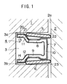
- FIG. 1 is a longitudinal cross-sectional view showing a combined oil ring which is fitted in an oil ring groove of the piston inserted into the cylinder in one preferred embodiment of the present invention.
- a combined oil ring 4 is fitted in an oil ring groove 3 formed on the outer circumferential surface of a piston 1 inside a cylinder 2.
- the combined oil ring 4 is comprised of a pair of upper and lower side rails 5 and 6 which are annular with a gap; and a spacer expander 7 which is annular with a gap.
- the spacer expander 7 is formed as follows.
- a material 30 shown in Fig. 2 is formed from a thin strip of austenitic stainless steel and has a symmetrical shape with respect to the center axis running longitudinally. That is, the thin steel strip of austenitic stainless steel is provided with a plurality of tortoise shell-like holes 15, in this example hexagonal holes 15, which serve as oil holes and are equally spaced in a longitudinal direction of the thin steel strip. Substantially V-shaped slits 16 and 17 are provided on both sides of the thin steel strip between the holes 15. This material 30 is bent symmetrically. In other words, the material 30 is bent along the bending lines A-A and B-B into a substantially U-shaped cross section.
- the upper and lower end portions are bent along the bending lines C-C and D-D to stand obliquely, and then the edges of the upper and lower standing portions are bent horizontally along the bending lines E-E and F-F.
- tufftriding treatment is performed.
- the material 30 after bending step and tufftriding treatment is then cut into a predetermined length, and formed to be annular so that the side rail pressing portions are arranged at the position of the inner peripheral side, and then formed on the outer circumferential surface by ion plating with a hard film of a mixture of CrN and Cr 2 N or a hard film of a mixture of CrN, Cr 2 N and Cr.
- This spacer expander 7 is composed of a plurality of periodic elements linked together peripherally and having a substantially U-shaped cross section. Each of these periodic elements has a horizontal upper portion 8 and lower portion 9 positioned at intervals in the axial direction. The outer circumferences of these upper and lower portions 8 and 9 are connected by an upright portion 10. Side rail pressing portions 11 and 12 are formed respectively obliquely facing inwards radially at the inner circumference of the upper portion 8 and lower portion 9. At the inner circumference of each of the side rail pressing portions 11 and 12, are inner portions 13 and 14 extending horizontally to the inner radial direction. Oil holes are formed in the upper portion 8, the upright portion 10 and the lower portion 9.
- the spacer expander 7 comprised of austenitic stainless steel is subjected to tufftriding treatment and formed on all surfaces with a soft-nitrided layer 20 as the under coating at a Vicker's hardness of HV900 to HV1200.
- a hard film 21 having a thickness of 1 ⁇ m to 50 ⁇ m and having a Vicker's hardness of HV1300 to HV2200 is formed by means of ion plating on the soft-nitrided layer 20 at the outer circumferential surface including the side rail pressing portions 11 and 12.
- the hard film 21 is a film of a mixture of CrN and Cr 2 N or a film of a mixture of CrN, Cr 2 N and Cr, and the crystal of CrN has a preferred orientation (200). Chromium plating may be employed instead of the soft-nitrided layer, as the under coating.
- the pair of side rails 5 and 6 are made of martensitic stainless steel, subjected to gas nitriding and formed with nitrided layers 22 and 23 on all surfaces. These side rails may be formed with nitrided layers on only the inner and outer circumferential surfaces by ion nitriding.
- the spacer expander 7 is provided in the oil ring groove 3 of the piston 1 in a compressed state with the paired ends abutting each other to exert an expanding force in outward radially.
- the pair of side rails 5 and 6 are supported separately above and below (axially) by the upper and lower portions 8 and 9.
- the upper and lower side rail pressing portions 11 and 12 apply pressure on the respective inner circumferential surfaces of the pair of side rails 5 and 6, so that the respective outer circumferential surfaces of the side rails 5 and 6 are made contact with the inner circumferential surface 2a of the cylinder 2, and the inner circumferential ends of the side rails 5 and 6 are made contact with the side surfaces 3a and 3b of the oil ring groove 3.
- the engine tests were performed utilizing a combined oil ring consisting of a spacer expander of austenitic stainless steel with the structure of the above embodiment, and side rails of martensitic stainless steel having gas nitriding performed on all surfaces.
- the amount of lubricating oil consumption indicating the wear resistance was measured, and after operating the engine for 300 hours, observations were made to detect cracks or peeling in the hard film of the side rail pressing portions.
- Tufftriding treatment was performed on the spacer expander to form a soft-nitrided layer with a Vicker's hardness of HV1000 on all surfaces of the spacer expander. Ion plating was then performed on the outer circumferential surface including the side rail pressing portions under the various conditions. The ion plating film had a thickness of 20 ⁇ m. The ion plating film obtained was subjected to X-ray diffraction analysis to identify the deposition phase and the Vicker's hardness was measured. Table 1 shows deposition phase structure, preferred orientation of the crystal of CrN and film hardness. No.
- the above-mentioned combined oil ring was utilized in a four cylinder diesel engine (bore I.D. 94mm) in endurance tests under high speed, full load conditions.
- the lubricating oil consumption was measured after engine operation at 50 hours and 300 hours.
- the side rail pressing portion of the spacer expander was observed under a stereo microscope at 50X power, and the hard film was examined for the presence of cracks or peeling.
- the results of the engine tests are shown in Table 2.
- the allowable upper limit for lubricating oil consumption is 40 grams per hour.
- No. Lubricating oil consumption for 50 hours of operation g/Hr Lubricating oil consumption for 300 hours of operation g/Hr Presence or absence of cracks or peeling
- Comparative Example 1 50 105 absence 2 32 55 presence 3 35 50 presence 4 35 52 presence 5 36 50 presence 6 34 55 presence 7 32 53 presence Embodiment 1 28 30 absence 2 25 28 absence 3 27 30 absence 4 28 31 absence 5 25 29 absence
- the spacer expander of the combined oil ring of the present invention is not limited by the form shown in the above embodiment.
- the inner portions 13 and 14 need not be provided in some configurations.
- the present invention is also applicable to combined oil rings provided with a spacer expander made of a plurality of radially corrugated periodic elements linked together in the circumferential direction.
Landscapes
- Engineering & Computer Science (AREA)
- General Engineering & Computer Science (AREA)
- Mechanical Engineering (AREA)
- Pistons, Piston Rings, And Cylinders (AREA)
- Physical Vapour Deposition (AREA)
Applications Claiming Priority (2)
| Application Number | Priority Date | Filing Date | Title |
|---|---|---|---|
| JP9366439A JPH11190429A (ja) | 1997-12-24 | 1997-12-24 | 組合せオイルリングのスペーサエキスパンダおよび組合せオイルリングならびにその製造方法 |
| JP36643997 | 1997-12-24 |
Publications (2)
| Publication Number | Publication Date |
|---|---|
| EP0927839A2 true EP0927839A2 (de) | 1999-07-07 |
| EP0927839A3 EP0927839A3 (de) | 2000-04-05 |
Family
ID=18486788
Family Applications (1)
| Application Number | Title | Priority Date | Filing Date |
|---|---|---|---|
| EP98310751A Withdrawn EP0927839A3 (de) | 1997-12-24 | 1998-12-24 | Zusammengesetzer Ölring und Verfahren zur Herstellung |
Country Status (2)
| Country | Link |
|---|---|
| EP (1) | EP0927839A3 (de) |
| JP (1) | JPH11190429A (de) |
Cited By (2)
| Publication number | Priority date | Publication date | Assignee | Title |
|---|---|---|---|---|
| DE102005019500B4 (de) * | 2005-04-27 | 2007-12-13 | Federal-Mogul Burscheid Gmbh | Schraubendruckfeder für Ölabstreifkolbenringe |
| CN113444998A (zh) * | 2021-06-28 | 2021-09-28 | 燕山大学 | 一种高强度奥氏体不锈钢低温气体渗氮方法 |
Citations (5)
| Publication number | Priority date | Publication date | Assignee | Title |
|---|---|---|---|---|
| JPS6422924U (de) | 1987-07-30 | 1989-02-07 | ||
| JPH01159449A (ja) | 1987-12-15 | 1989-06-22 | Riken Corp | 複合窒化層を有するピストンリング |
| JPH0625597A (ja) | 1992-07-07 | 1994-02-01 | Toyota Motor Corp | 自動車用層間耐チッピング塗料 |
| JPH06235462A (ja) | 1993-02-08 | 1994-08-23 | Riken Corp | 内燃機関用ピストンリング |
| JPH09170659A (ja) | 1995-12-19 | 1997-06-30 | Teikoku Piston Ring Co Ltd | 組合せオイルリングのスペーサエキスパンダおよび組合せオイルリング |
Family Cites Families (9)
| Publication number | Priority date | Publication date | Assignee | Title |
|---|---|---|---|---|
| JPS59127860U (ja) * | 1983-02-18 | 1984-08-28 | 日本ピストンリング株式会社 | 組合せオイルリング |
| JPH01156461A (ja) * | 1987-12-14 | 1989-06-20 | Riken Corp | ピストンリングの表面処理方法 |
| JPH0723650Y2 (ja) * | 1990-05-14 | 1995-05-31 | ヤンマーディーゼル株式会社 | シリンダとピストンリングの組合せ |
| JP2739722B2 (ja) * | 1992-12-28 | 1998-04-15 | 株式会社リケン | ピストンリング |
| JP3350157B2 (ja) * | 1993-06-07 | 2002-11-25 | 帝国ピストンリング株式会社 | 摺動部材およびその製造方法 |
| EP0702097B1 (de) * | 1994-07-30 | 1999-11-10 | Kabushiki Kaisha Riken | Gleitkörper |
| JP3766445B2 (ja) * | 1994-12-27 | 2006-04-12 | 日本ピストンリング株式会社 | 内燃機関用ピストンリング |
| JP3452675B2 (ja) * | 1995-01-19 | 2003-09-29 | 帝国ピストンリング株式会社 | 摺動部材およびその製造方法 |
| JP3728740B2 (ja) * | 1995-04-28 | 2005-12-21 | 日本ピストンリング株式会社 | 内燃機関用ピストンリング |
-
1997
- 1997-12-24 JP JP9366439A patent/JPH11190429A/ja active Pending
-
1998
- 1998-12-24 EP EP98310751A patent/EP0927839A3/de not_active Withdrawn
Patent Citations (5)
| Publication number | Priority date | Publication date | Assignee | Title |
|---|---|---|---|---|
| JPS6422924U (de) | 1987-07-30 | 1989-02-07 | ||
| JPH01159449A (ja) | 1987-12-15 | 1989-06-22 | Riken Corp | 複合窒化層を有するピストンリング |
| JPH0625597A (ja) | 1992-07-07 | 1994-02-01 | Toyota Motor Corp | 自動車用層間耐チッピング塗料 |
| JPH06235462A (ja) | 1993-02-08 | 1994-08-23 | Riken Corp | 内燃機関用ピストンリング |
| JPH09170659A (ja) | 1995-12-19 | 1997-06-30 | Teikoku Piston Ring Co Ltd | 組合せオイルリングのスペーサエキスパンダおよび組合せオイルリング |
Cited By (2)
| Publication number | Priority date | Publication date | Assignee | Title |
|---|---|---|---|---|
| DE102005019500B4 (de) * | 2005-04-27 | 2007-12-13 | Federal-Mogul Burscheid Gmbh | Schraubendruckfeder für Ölabstreifkolbenringe |
| CN113444998A (zh) * | 2021-06-28 | 2021-09-28 | 燕山大学 | 一种高强度奥氏体不锈钢低温气体渗氮方法 |
Also Published As
| Publication number | Publication date |
|---|---|
| JPH11190429A (ja) | 1999-07-13 |
| EP0927839A3 (de) | 2000-04-05 |
Similar Documents
| Publication | Publication Date | Title |
|---|---|---|
| US5718437A (en) | Combined oil ring with spacer/expander having Cr2 N coating thereon | |
| US5820131A (en) | Piston ring having wear coating consisting of Cr2 N or a mixture of Cr2 N and Cr | |
| EP0507636B1 (de) | Zusammengesetzer Ölring | |
| US6149162A (en) | Sliding member | |
| EP1431630A2 (de) | Zusammengesetzer Ölring | |
| EP2578908A1 (de) | Ölring für einen verbrennungsmotor | |
| EP2562448B1 (de) | Ölring für einen verbrennungsmotor | |
| EP2162561B1 (de) | Kolbenring mit sulfonitrierungsbehandlung | |
| EP3421846A1 (de) | Kolbenring | |
| US20080256794A1 (en) | Method For the Production of a Piston Ring For Internal Combustion Engine and a Piston Ring of this Type | |
| EP3163129A1 (de) | Kolbenring | |
| US8393800B2 (en) | Needle roller bearing and crankshaft support structure | |
| JPH09144881A (ja) | 組合せオイルリング | |
| GB2314604A (en) | Piston ring | |
| US10295058B2 (en) | Piston ring | |
| JPS6145172A (ja) | コイルエキスパンダ付オイルリング | |
| KR100496709B1 (ko) | 질화표면층을 가진 2조각 오일제어링 | |
| GB2153488A (en) | Nitrided steel piston ring | |
| US20040040436A1 (en) | Combination of piston and piston ring | |
| EP0927839A2 (de) | Zusammengesetzer Ölring und Verfahren zur Herstellung | |
| CN107002872A (zh) | 油环 | |
| JPH0544839A (ja) | 組合せオイルリング | |
| JPH11190430A (ja) | ピストンリングおよびその製造方法 | |
| JPH09196173A (ja) | 組合せオイルリング | |
| JPH08170563A (ja) | ピストンリングの組合せ |
Legal Events
| Date | Code | Title | Description |
|---|---|---|---|
| PUAI | Public reference made under article 153(3) epc to a published international application that has entered the european phase |
Free format text: ORIGINAL CODE: 0009012 |
|
| AK | Designated contracting states |
Kind code of ref document: A2 Designated state(s): DE GB |
|
| AX | Request for extension of the european patent |
Free format text: AL;LT;LV;MK;RO;SI |
|
| PUAL | Search report despatched |
Free format text: ORIGINAL CODE: 0009013 |
|
| AK | Designated contracting states |
Kind code of ref document: A3 Designated state(s): AT BE CH CY DE DK ES FI FR GB GR IE IT LI LU MC NL PT SE |
|
| AX | Request for extension of the european patent |
Free format text: AL;LT;LV;MK;RO;SI |
|
| RIC1 | Information provided on ipc code assigned before grant |
Free format text: 7F 16J 9/06 A, 7F 16J 9/20 B |
|
| 17P | Request for examination filed |
Effective date: 20000522 |
|
| AKX | Designation fees paid |
Free format text: DE GB |
|
| 17Q | First examination report despatched |
Effective date: 20030422 |
|
| STAA | Information on the status of an ep patent application or granted ep patent |
Free format text: STATUS: THE APPLICATION IS DEEMED TO BE WITHDRAWN |
|
| 18D | Application deemed to be withdrawn |
Effective date: 20030903 |