EP0927889B1 - Justierbarer Magnet für die Magnetresonanzbildgebung während medizinischer Eingriffe - Google Patents
Justierbarer Magnet für die Magnetresonanzbildgebung während medizinischer Eingriffe Download PDFInfo
- Publication number
- EP0927889B1 EP0927889B1 EP98310426A EP98310426A EP0927889B1 EP 0927889 B1 EP0927889 B1 EP 0927889B1 EP 98310426 A EP98310426 A EP 98310426A EP 98310426 A EP98310426 A EP 98310426A EP 0927889 B1 EP0927889 B1 EP 0927889B1
- Authority
- EP
- European Patent Office
- Prior art keywords
- magnet assembly
- magnets
- base
- magnetic field
- patient
- Prior art date
- Legal status (The legal status is an assumption and is not a legal conclusion. Google has not performed a legal analysis and makes no representation as to the accuracy of the status listed.)
- Expired - Lifetime
Links
- 238000002595 magnetic resonance imaging Methods 0.000 title claims description 21
- 230000005291 magnetic effect Effects 0.000 claims description 62
- 238000003384 imaging method Methods 0.000 claims description 33
- 230000008878 coupling Effects 0.000 claims description 18
- 238000010168 coupling process Methods 0.000 claims description 18
- 238000005859 coupling reaction Methods 0.000 claims description 18
- 238000013152 interventional procedure Methods 0.000 claims description 13
- 230000000007 visual effect Effects 0.000 claims description 13
- 230000000712 assembly Effects 0.000 claims description 6
- 238000000429 assembly Methods 0.000 claims description 6
- 230000004907 flux Effects 0.000 claims description 6
- 239000003302 ferromagnetic material Substances 0.000 claims description 2
- 230000004323 axial length Effects 0.000 claims 1
- 150000002505 iron Chemical class 0.000 claims 1
- 238000005457 optimization Methods 0.000 claims 1
- 238000000034 method Methods 0.000 description 6
- 238000010586 diagram Methods 0.000 description 4
- 210000004204 blood vessel Anatomy 0.000 description 3
- 238000004804 winding Methods 0.000 description 3
- XEEYBQQBJWHFJM-UHFFFAOYSA-N Iron Chemical compound [Fe] XEEYBQQBJWHFJM-UHFFFAOYSA-N 0.000 description 2
- 230000005294 ferromagnetic effect Effects 0.000 description 2
- 230000007246 mechanism Effects 0.000 description 2
- 238000012856 packing Methods 0.000 description 2
- 206010009244 Claustrophobia Diseases 0.000 description 1
- 241001465754 Metazoa Species 0.000 description 1
- 210000001367 artery Anatomy 0.000 description 1
- 238000001574 biopsy Methods 0.000 description 1
- 238000012937 correction Methods 0.000 description 1
- 230000001419 dependent effect Effects 0.000 description 1
- 238000011156 evaluation Methods 0.000 description 1
- 238000002513 implantation Methods 0.000 description 1
- 229910052742 iron Inorganic materials 0.000 description 1
- 210000003127 knee Anatomy 0.000 description 1
- 210000000056 organ Anatomy 0.000 description 1
- 230000008520 organization Effects 0.000 description 1
- 208000019899 phobic disease Diseases 0.000 description 1
- 238000001356 surgical procedure Methods 0.000 description 1
- 210000003462 vein Anatomy 0.000 description 1
Images




Classifications
-
- G—PHYSICS
- G01—MEASURING; TESTING
- G01R—MEASURING ELECTRIC VARIABLES; MEASURING MAGNETIC VARIABLES
- G01R33/00—Arrangements or instruments for measuring magnetic variables
- G01R33/20—Arrangements or instruments for measuring magnetic variables involving magnetic resonance
- G01R33/28—Details of apparatus provided for in groups G01R33/44 - G01R33/64
- G01R33/38—Systems for generation, homogenisation or stabilisation of the main or gradient magnetic field
- G01R33/3806—Open magnet assemblies for improved access to the sample, e.g. C-type or U-type magnets
-
- G—PHYSICS
- G01—MEASURING; TESTING
- G01R—MEASURING ELECTRIC VARIABLES; MEASURING MAGNETIC VARIABLES
- G01R33/00—Arrangements or instruments for measuring magnetic variables
- G01R33/20—Arrangements or instruments for measuring magnetic variables involving magnetic resonance
- G01R33/28—Details of apparatus provided for in groups G01R33/44 - G01R33/64
- G01R33/38—Systems for generation, homogenisation or stabilisation of the main or gradient magnetic field
- G01R33/383—Systems for generation, homogenisation or stabilisation of the main or gradient magnetic field using permanent magnets
Definitions
- This invention relates to an open architecture superconducting magnet assembly for a magnetic resonance imager (hereinafter called "MRI"), and more particularly to an adjustable, versatile assembly which facilitates interventional procedures.
- MRI magnetic resonance imager
- MRI magnet assemblies Another important application of open MRI magnet assemblies is for interventional procedures wherein the physician or surgeon can access the patient for such procedures while observing the display of a selected internal portion of the patient such as the region being operated on or treated for example, by lasers or by surgical instruments or mechanisms inserted into the patients blood vessels or organs.
- An open architecture magnet assembly with selectively adjustable magnetic field orientation is know from JP-A-63286142 disclosing an assembly being supported on a base and comprising spaced apart permanent magnet pole faces and a u-shaped yoke flux return path.
- the magnets are selectively rotatable about two axes which are substantially parallel to the base to control the orientation and position of the magnetic field relative to said base.
- Documents US-A-4 985 678 and US-A-5490 509 disclose shimming coils positioned on the pole faces .
- Document US-A-4 673 882 discloses a closed magnet assembly having ferromagnetic bars mounted in pole members to correct the magnet field between the pole members. An adjustment of the magnetic field is also achieved by disposing coils around the bars outside the imagine volume.
- an open architecture magnet assembly is provided as defined in claim 1. Additional features are set forth in the dependent claims.
- a closed ferromagnetic path forms a generally C-shaped magnet structure which is selectively rotatable about a plurality of axes parallel to the MRI base in order to selectively control the inclination of the magnetic field from at least the vertical to the horizontal and to optimize the imaging of a patient in the imaging area.
- Motor driven gearing is used to control movement of the magnets.
- the control of current flow through a plurality of shimming coils adjacent to the imaging area provides corrections for magnetic field inhomogeneities at the selected magnetic field inclination and position.
- a visual MRI display at the magnet assembly enables real-time interventional procedures by a physician or surgeon.
- the assembly may be more portable by mounting on a shielded direct current motorized moveable base.
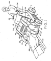
- a portable magnet assembly 10 includes a base 2 supported on wheels 4 driven by direct current electric motors indicated generally as 6.
- Housing 11 on base 2 includes the power source such as rechargeable batteries shown generally within the dotted areas 12 of FIGs 2 and 3.
- a pair of spaced apart permanent magnets 14 and 16 define imaging volume 21 therebetween and establish a strong unified magnetic field in the imaging volume.
- a magnetic flux path between magnets 14 and 16 is provided by arms or members 18 and 20 and flux path member 24 all of which are ferromagnetic material to complete the magnetic path between the magnets.
- a pair of gear drive assemblies or rotatable couplings 26 and 28 are positioned at each end of adjustable magnetic positioning member 29. Rotatable coupling 26 interconnects base 2 and magnetic positioning member 29 while rotatable coupling 28 interconnects the magnetic positioning member and magnetic flux path member 24. Rotatable coupling 26 provides movement of magnetic positioning member 29 in the direction indicated by arrows 48 (see FIG.
- rotatable coupling 28 provides rotation of arms 18 and 20, and magnets 14 and 16, respectively, in the direction shown by arrows 50.
- the combined adjustability made possible through rotatable couplings 26 and 28 facilitates the selective positioning of magnets 14 and 16 about a desired portion, such as the head 46 of a patient 44 on a horizontal patient support 40 (see FIG. 2) which support may be a Trandelinberg mobile table which is moveable along floor 3 on mobile table wheels 43.
- a patient may be examined while in alternate patient support such as wheelchair 42.
- the driving assemblies or rotatable couplings 26 and 28 may conveniently comprise a direct current motor driven gear chain (described in more detail below) powered by rechargeable batteries 12 and controlled by healthcare provider 36 which may be a technician, physician, or a surgeon operating controls shown generally as 34 to position magnet assembly 10 and permanent magnets 14 and 16 in the desired position for the MRI examination of patient 44 whether on a horizontal support or in a wheelchair.
- a visual display or indicator 38 assists healthcare giver 36 to properly position permanent magnets 14 and 16, and in addition to control the rotation and hence the orientation of the magnets such that the orientation or inclination of the magnetic field therebetween can be adjusted over 90 or more degrees.
- the inclination of the magnetic flux lines or field B can be adjusted from the vertical to the horizontal relative to floor 3, or over a greater range, including any selected position therebetween.
- a magnetic shimming assembly comprising a plurality of magnetic members is carried in trays or drawers shown generally as 30 and 32 for movement along with their respective permanent magnets 14 and 16. For each preset position of the magnetic field other predetermined magnetic members may be added to drawer assemblies 30 and 32.
- a suitable magnetic shimming assembly to improve the homogeneity of the magnetic field within imaging volume 21, see United States Patent 5,389,909 entitled "Open Architecture Magnetic Resonance Imaging Passively Shimmed Superconducting Magnet Assembly", assigned to the same Assignee as the present invention.
- Shim members 104 are positioned over or embedded in the face 105 of one or both of magnets 14 and 16 adjacent imaging volume 21.
- Shim members 104 include windings 106 surrounding an iron laminate pin or cylinder 108 which could alternatively utilize a hexagonal or other polygonal cross-section such as the hexagon cross-section 110 of shim member 112 to enable a greater density or closer packing of the shim members on the face 105.
- a dense packing is not shown in FIG. 10 but may be desirable for increased magnetic field homogeneity.
- Windings 106 are each connected to a variable direct current voltage source 116 via bifilar twisted leads 120 to control the superconducting current flow through the bifilar windings and to vary the flow for each preset position of the magnetic field.
- Computer 100 may be programmed to provide the desired bifilar current flow for each of the shim coils at each of the preset positions of the magnetic field.
- the bifilar wound leads cancel undesired magnetic fields and forces that current flow though the leads might otherwise introduce and which could disturb the homogeneity of the magnetic field in imaging volume 21 between magnets 14 and 16.
- the ends of all of the shim coils 106 would be connected to a direct current voltage source such as 116 controlled by computer 100 to provide the proper current for each preset or new position of the magnetic field.
- a direct current voltage source such as 116 controlled by computer 100 to provide the proper current for each preset or new position of the magnetic field.
- multiple coils at scattered locations could be connected to the same voltage source with the shimming current flow there through controlled by computer 100 varying the resistance in series with the voltage source.
- the computer controlled shimming could provide an automatic second fine tuning of magnetic field homogeneity after a patient was positioned between magnets 14 and 16 to further enhance the quality of the imaging.
- FIG. 4 shows a larger non-portable magnet assembly 10 without wheels 4 but with a simplified magnetic adjustment drive.
- base 2 is secured to, or positioned directly on, floor 3 such that patient 44 is moved between permanent magnets 14 and 16 on a horizontal support such as shown in FIGs. 4 and 5, or else seated in a tiltable seat 45.
- Non-ferromagnetic coupling gears 52 and 54 including gear teeth such as those indicated generally as 56 which mesh with gear teeth 58 on base 2 and which also provide part of the magnetic return path between magnets 14 and 16.
- Permanent magnets 14 and 16 may be rotated manually by control 64 on lever arms 66 as shown in simplified form in FIG. 5 or may be rotated by a motor driven gear drive shown generally as 59.
- Magnet assembly 10 thus can be rotated as indicated by arrow 68 around patient 44 who may be positioned within imaging volume in the central region between permanent magnets 14 and 16 as indicated by arrow 21 and raised or lowered by adjustment of patient support 40.
- Dotted lines 72, 73 and 74 in FIGs. 5 and 6 indicate selectively controllable inclination and orientation of the magnetic field between magnets 14 and 16 in imaging volume or region 21, while arrow 76 illustrates movement or adjustment of the magnetic field inclination indicated by arrow 17 (see FIG. 4) from the vertical to a position approximately 45 degrees to vertical to improve imaging of a particular area of patient 44.
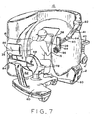
- FIG. 7 illustrates the access by a physician or surgeon 36 to patient 44 on patient support 40.
- Patient support 40 extends between the magnets to the imaging region 21 such that patient 44 being imaged is directly accessible to the physician or surgeon 36 for interventional procedures.
- interventional procedures may include surgery, the positioning of surgical devices or sensors within the body such as in a vein or artery, and the implantation of medical devices within patient 44.
- Such procedures are facilitated by providing the surgeon with one or more video displays formatted and integrated by the MRI system as described in more detail below regarding FIG. 8.
- Visual display 38 can be a conventional display from the MRI imaging system while visual display 39, could be, for example, a three-dimensional blood vessel reconstruction provided by the MRI computer. That is, the surgeon can be provided with real time magnetic resonance imaging to facilitate and enable internal procedures in which direct visual observation by the surgeon is inadequate.
- surgeon 36 is seated on adjustable seat 78 on moveable platform 80 of surgeon's station 82 which also includes a surgeon's control panel 84, indicators 86 and controls such as 88 to enable the surgeon to position and adjust permanent magnets 14 and 16 to provide the optimum imaging of patient 44.
- Visual display 39 may be adjustably positioned by adjustment of articulated boom members 41 and 90 about adjustable joints 92 and 94.
- Control panel 96 on visual display 39 enables surgeon 36 to select the particular display desired from the MRI computer 100 (shown in FIG. 8).
- FIG. 8 is a block diagram, partially in pictorial form which better illustrates the electrical interconnection of the components shown in FIGs. 1-7.
- Magnet assembly 10 is connected to computer 100 with its associated display 102.
- Computer 100 also generates the desired display at magnet assembly 10, which if mobile will include wheels 4.
- These displays include visual display 38 which may be the same or essentially the same as that shown by display 102 at computer 100.
- Computer 100 also provides visual display 39 with 3-dimensional blood vessel reconstruction images or other images as selected by control 96 associated with the visual display.
- Display 39 shows a simplified sketch of the type of display which may be selected.
- a further optional display may include a head mounted display 47 which may be worn by surgeon 36 through use of resilient band 43 in the same manner as goggles or eyeglasses, or positioned over the surgeon's eyeglasses This enables surgeon 36 to avoid having to look up or away at a display such as 39 during interventional procedures on patient 44.
- a head mounted display 47 which may be worn by surgeon 36 through use of resilient band 43 in the same manner as goggles or eyeglasses, or positioned over the surgeon's eyeglasses This enables surgeon 36 to avoid having to look up or away at a display such as 39 during interventional procedures on patient 44.
- FIG. 9 is a block diagram showing one form of a rotatable coupling or gear drive assembly such as 26, 28 and 59.
- Direct current motor 104 is controlled by positioning control 34 and connected gear train 106 and driving gear 108 to the driven member which may be part of rotatable coupling 26 at base 2, or part of rotatable coupling 28 at the end of arms 18 and 20, or rotatable coupling 59 which directly rotates magnets 14 and 16.
- the present invention provides a flexible, adjustable magnet assembly for MRI imaging and interventional procedures providing mobility, adjustability, positioning and magnetic field 17 rotational capabilities for permanent magnets 14 and 16 which define imaging volume 21 of magnet assembly 10.
- This enables healthcare worker 16 to position patient 44 in a sitting prone or inclined position while at the same time positioning and orienting magnets 14 and 16 and the resultant magnet field 17 in imaging volume 21 at the desired inclination or orientation to enhance both the imaging of the patient and the accessibility of the patient to the surgeon for interventional procedures.
- a 45 degree orientation may be desirable, for example, for the imaging of knees, while a thirty degree field orientation may be desirable for an MRI guided biopsy of the spine of a prone patient.
- Magnetic field orientations which are intermediate the vertical and horizontal of the main axis of the human body provide better access to the human body for medical interventional procedures.
- Orienting magnetic field inclination 17 transverse to human body 44 but parallel to the plane of floor 3 allows for the structural supports maintaining the gap between the magnet halves to be arranged at different positions.
- the positions of the structural supports will be selected to give the maximum open space in the vertical direction, however, selection of these positions is determined by the need to position human body or patient 44 for the selected medical procedure.
- the flexibility possible with adjustable magnet assembly 10 facilities imaging of people that cannot maintain a lying position increases patient support possibilities including typical weight bearing positions for medical evaluation.
- a vertical access configuration allows patient entry from one side of the system with comparable access for the clinician 36 from the other side (as shown in FIGs. 4 and 7) for direct manipulation of patient 44.
- Different applications are optimized by the transportability and adjustability of the same magnet assembly 10 to the position most appropriate for the imaging of selected application with the shimming system optimizing the quality of the image for the selected position.
Landscapes
- Physics & Mathematics (AREA)
- Condensed Matter Physics & Semiconductors (AREA)
- General Physics & Mathematics (AREA)
- Magnetic Resonance Imaging Apparatus (AREA)
Claims (26)
- Magnetanordnung (10) mit offener Architektur, mit wahlgemäß einstellbarer Magnetfeldorientierung für interventionelle Magnetresonanz-Bildgebung (Kernspintomographie), mit:wobei die Magnete (14, 16) wahlgemäß um wenigstens eine Achse drehbar sind, welche im wesentlichen parallel zu der Basis liegt/liegen, um die Orientierung und Position des Magnetfeldes relativ zu der Basis zu steuern, um eine Optimierung der Bildgebung eines ausgewählten Bereichs des Patienten in dem Bildgebungsvolumen zu ermöglichen; wobei die Magnetanordnung aufweist:einer Basis (2), einem Paar von der Basis unterstützter Magnete (14, 16) mit entsprechenden in Abstand angeordneten Magnetpolflächen, die in dem Raum zwischen den Magneten (14, 16) ein Magnetfeld und ein Bildgebungsvolumen (21) erzeugen;wenigstens einem Element (24), das sich außerhalb des Bildgebungsvolumens erstreckt, um einen magnetischen Rückschlusspfad für die Magnete (14, 16) zu erzeugen;wobei die Einrichtung zum Anpassen der Magnetfeldhomogenität mehrere Shimming-Spulen (Trimmspulen) (106), verteilt auf wenigstens einem der Magneten, angrenzend an das Bildgebungsvolumen enthält, jede Spule (106) einen entsprechenden Magnetkern umgibt, und ein automatischer Stromfluss durch die Shimming-Spulen an jeder ausgewählten Position und Orientierung des Magnetfeldes vorgesehen ist.eine Einrichtung (104), um die Magnetfeldhomogenität innerhalb des Bildgebungsvolumens bei mehreren ausgewählten Orientierungen und Positionen des Magnetfeldes automatisch anzupassen;
- Magnetanordnung nach Anspruch 1, wobei die Magnete (14, 16) wahlgemäß um mehrere Achsen drehbar sind, welche im wesentlichen parallel zu der Basis sind, so dass die Orientierung des Magnetfeldes über wenigstens ungefähr 90 Grad einstellbar ist.
- Magnetanordnung nach Anspruch 2, wobei sich die ungefähr 90 Grad von ungefähr der Vertikalen bis zu der Horizontalen im Bezug auf die Basis erstrecken.
- Magnetanordnung nach Anspruch 2 mit einem Computer (100), der den Strom für jede von den Shimming-Spulen (106) mit vorbestimmten Stromflüssen für voreingestellte Positionen der Magnete steuert.
- Magnetanordnung nach Anspruch 4, wobei die Shimming-Spulen dafür eingerichtet sind, Strom durch entsprechende bifilar verdrillte Leiterpaare aufzunehmen.
- Magnetanordnung nach Anspruch 5, wobei die Magnetkerne aus laminiertem Eisen bestehen.
- Magnetanordnung nach Anspruch 6, wobei die laminierten Kerne einen polygonalen Querschnitt aufweisen.
- Magnetanordnung nach Anspruch 2, wobei wenigstens ein Element (24) aus ferromagnetischem Material besteht.
- Magnetanordnung nach Anspruch 3, wobei die Magnete um die Basis herum verstellbar sind, um den Zugang des Arztes zu einem in den Bildgebungsvolumen zu positionierenden Patienten (94) zu optimieren.
- Magnetanordnung nach Anspruch 9, mit einer Patientenlagerungseinrichtung (40), um den Patienten (44) in einer aus der aus Sitzen und Liegen bestehenden Positionsgruppe ausgewählten Position zu positionieren.
- Magnetanordnung nach Anspruch 10, wobei die Sitzposition verstellbar ist und einen Sitz mit einem Lagerungsabschnitt enthält, dessen Winkel in Bezug auf die Basis verstellt werden kann.
- Magnetanordnung nach Anspruch 11, wobei die Magnete (14, 16) im Allgemeinen eine zylindrische Form mit einer axialen Länge deutlich kleiner als ihr Umfang aufweisen.
- Magnetanordnung nach Anspruch 1, wobei die Magnete wahlgemäß in zwei Richtungen bewegbar sind.
- Magnetanordnung nach Anspruch 13, wobei die Magnete mit der Basis über wenigstens zwei wahlgemäß drehbare Kupplungen (26, 28) verbunden sind.
- Magnetanordnung nach Anspruch 14, wobei die erste von den wenigstens zwei Kupplungen an der Basis befestigt ist, und mit der zweiten von den wenigstens zwei Kupplungen über ein starres Verbindungselement verbunden ist, das Drehungen der Magnete (14, 16) über ungefähr 90 Grad um die zu der Basis parallelen zwei Achsen ermöglicht.
- Magnetanordnung nach Anspruch 15, wobei jede von den Kupplungen eine motorbetriebene Getriebekupplung ist.
- Magnetanordnung nach Anspruch 16, wobei die Basis (3) für eine Positionierung um einen Patienten (44) herum beweglich ist.
- Magnetanordnung nach Anspruch 17, mit Rädern (4) auf der Basis und einem elektrischen Antrieb zum wahlgemäßen Positionieren der Magnetanordnung.
- Magnetanordnung nach Anspruch 18, mit einer auf der Basis montierten wiederaufladbaren Batterie und Gleichstrommotoren zum Positionieren der Basis und für den Antrieb der Getriebekupplungen.
- Magnetanordnung nach Anspruch 19, mit Steuerungen für jeden von den Motoren der Magnetanordnung.
- Magnetanordnung nach Anspruch 20, wobei der Raum zwischen den Magneten wählbar ist, um zu ermöglichen, dass die Magnete einen Patienten auf einer aus einer Sitzpositionslagerung und einer im Wesentlichen liegenden Positionslagerung ausgewählten Lagerung umgeben.
- Magnetanordnung nach Anspruch 1, wobei die Magnetanordnung wenigstens zwei motorbetriebene Getriebeanordnungen enthält, um die Permanentmagnete zu positionieren und die Magnetfeldorientierung zu verstellen.
- Magnetanordnung (10) nach Anspruch 1, mit einer in der Nähe der Magnete (14, 16) angeordneten visuellen Magnetresonanz-Anzeigeeinrichtung (38), um einer in der Gesundheitsfürsorge arbeitenden Person zu ermöglichen, die Anzeige zu betrachten, während sie sich in einer interventionellen Prozedur an einem zwischen den Magneten (14, 16) positionierten Patienten (44) befindet.
- Magnetanordnung nach Anspruch 23, wobei die visuelle Anzeigeeinrichtung (39) einstellbar an der Magnetanordnung befestigt ist.
- Magnetanordnung nach Anspruch 1 mit einer visuellen Magnetresonanz-Anzeigeeinrichtung (47), welche zum Tragen auf dem Kopf eines Arztes zur Bewegung damit angepasst ist, um die Anzeigeeinrichtung (47) zu betrachten, während er sich in einem interventionellen Prozedur an einem zwischen den Magneten (14, 16) positionierten Patienten (44) befindet.
- Magnetanordnung nach einem der Ansprüche 23-25, die ferner einen Computer (100) enthält, um rekonstruierte dreidimensionale Bilder an die Magnetresonanz-Anzeigeeinrichtung (38) zu liefern, und um den Stromfluss durch die Magnet-Shimming-Spulen an vorgewählten Orientierungen des Magnetfeldes zu steuern.
Applications Claiming Priority (2)
| Application Number | Priority Date | Filing Date | Title |
|---|---|---|---|
| US09/002,465 US6011396A (en) | 1998-01-02 | 1998-01-02 | Adjustable interventional magnetic resonance imaging magnet |
| US2465 | 1998-01-02 |
Publications (3)
| Publication Number | Publication Date |
|---|---|
| EP0927889A2 EP0927889A2 (de) | 1999-07-07 |
| EP0927889A3 EP0927889A3 (de) | 2001-04-18 |
| EP0927889B1 true EP0927889B1 (de) | 2005-12-28 |
Family
ID=21700897
Family Applications (1)
| Application Number | Title | Priority Date | Filing Date |
|---|---|---|---|
| EP98310426A Expired - Lifetime EP0927889B1 (de) | 1998-01-02 | 1998-12-18 | Justierbarer Magnet für die Magnetresonanzbildgebung während medizinischer Eingriffe |
Country Status (4)
| Country | Link |
|---|---|
| US (1) | US6011396A (de) |
| EP (1) | EP0927889B1 (de) |
| JP (1) | JP4165949B2 (de) |
| DE (1) | DE69832951T2 (de) |
Cited By (1)
| Publication number | Priority date | Publication date | Assignee | Title |
|---|---|---|---|---|
| US8126245B2 (en) | 2006-06-06 | 2012-02-28 | Esaote, S.P.A. | Apparatus for magnetic resonance imaging of patients with limbs, particularly lower limbs, under natural stress |
Families Citing this family (70)
| Publication number | Priority date | Publication date | Assignee | Title |
|---|---|---|---|---|
| US6023165A (en) * | 1992-09-28 | 2000-02-08 | Fonar Corporation | Nuclear magnetic resonance apparatus and methods of use and facilities for incorporating the same |
| US6411187B1 (en) | 1997-07-23 | 2002-06-25 | Odin Medical Technologies, Ltd. | Adjustable hybrid magnetic apparatus |
| AU9364698A (en) | 1997-09-25 | 1999-04-12 | Odin Technologies Ltd. | Magnetic apparatus for mri |
| US7127802B1 (en) | 1997-11-21 | 2006-10-31 | Fonar Corporation | Method of fabricating a composite plate |
| JP3110011B2 (ja) * | 1998-01-28 | 2000-11-20 | ジーイー横河メディカルシステム株式会社 | Mri装置および移動型テーブル |
| JP3034841B2 (ja) * | 1998-06-05 | 2000-04-17 | ジーイー横河メディカルシステム株式会社 | Mri用コイル、クレードル及びmri装置 |
| JP3040748B2 (ja) * | 1998-06-15 | 2000-05-15 | ジーイー横河メディカルシステム株式会社 | Mri用垂直マグネット装置およびmri装置 |
| IT1305971B1 (it) | 1998-08-31 | 2001-05-21 | Esaote Spa | Macchina per il rilevamento di immagini in risonanza magneticanucleare del tipo dedicato al rilevamento d'immagini di limitate |
| IT1304768B1 (it) * | 1998-10-05 | 2001-03-29 | Esaote Spa | Lettino porta paziente o simili, e macchina, in particolare macchinaper il rilevamento d'immagini in risonanza magnetica nucleare in |
| AU1582400A (en) * | 1998-12-08 | 2000-06-26 | Odin Medical Technologies Ltd | A device and a system for moving and positioning an open magnetic resonance imaging probe |
| US6591127B1 (en) * | 1999-03-15 | 2003-07-08 | General Electric Company | Integrated multi-modality imaging system and method |
| DE19923947A1 (de) * | 1999-05-25 | 2000-12-07 | Siemens Ag | Magnetresonanztomographiegerät, insbesondere für den interoperativen Einsatz |
| JP2003502085A (ja) * | 1999-06-14 | 2003-01-21 | コーニンクレッカ フィリップス エレクトロニクス エヌ ヴィ | 電気的に接続された機器用の妨害防止供給導線を有するmri装置 |
| US6317619B1 (en) * | 1999-07-29 | 2001-11-13 | U.S. Philips Corporation | Apparatus, methods, and devices for magnetic resonance imaging controlled by the position of a moveable RF coil |
| DE19959720B4 (de) * | 1999-12-10 | 2005-02-24 | Siemens Ag | Verfahren zum Betrieb eines Magnetresonanztomographiegeräts |
| DE10114013B4 (de) * | 2001-03-22 | 2005-06-23 | Siemens Ag | Magnetresonanzanlage |
| US6504461B2 (en) * | 2001-03-26 | 2003-01-07 | General Electric Company | Open magnet with recessed field shaping coils |
| US6934574B1 (en) | 2001-06-21 | 2005-08-23 | Fonar Corporation | MRI scanner and method for modular patient handling |
| US6944492B1 (en) * | 2001-10-01 | 2005-09-13 | Fonar Corporation | Patient bed support for an open MRI system |
| US7906966B1 (en) | 2001-10-05 | 2011-03-15 | Fonar Corporation | Quadrature foot coil antenna for magnetic resonance imaging |
| US7701209B1 (en) | 2001-10-05 | 2010-04-20 | Fonar Corporation | Coils for horizontal field magnetic resonance imaging |
| JP3701616B2 (ja) * | 2002-03-06 | 2005-10-05 | ジーイー・メディカル・システムズ・グローバル・テクノロジー・カンパニー・エルエルシー | 磁気共鳴撮影装置 |
| US7123008B1 (en) | 2002-04-19 | 2006-10-17 | Fonar Corporation | Positional magnetic resonance imaging |
| US8036730B1 (en) | 2002-04-19 | 2011-10-11 | Fonar Corporation | Temporal magnetic resonance imaging |
| WO2003094727A1 (fr) * | 2002-05-13 | 2003-11-20 | Hitachi Medical Corporation | Systeme d'imagerie par resonance magnetique |
| DE10224192A1 (de) * | 2002-05-31 | 2003-12-18 | Fraunhofer Ges Forschung | Bildgebendes NMR-Verfahren sowie NMR-Vorrichtung |
| US6984982B2 (en) * | 2002-07-29 | 2006-01-10 | Ge Medical Systems Global Technology Company Llc | Method and system for shimming an MRI magnet assembly |
| JP2006507095A (ja) * | 2002-11-25 | 2006-03-02 | フォーナー・コーポレイション | Mriデュアルスキャニングのための方法、装置、及び施設 |
| US7102353B1 (en) | 2002-11-29 | 2006-09-05 | Fonar Corporation | Magnetic resonance imaging apparatus having moving magnets |
| US6954070B2 (en) * | 2003-01-06 | 2005-10-11 | Brk Wireless Company, Inc. | NMR imaging system with conical permanent magnet |
| US8064984B2 (en) | 2003-03-18 | 2011-11-22 | Esaote S.P.A. | Magnetic resonance imaging apparatus |
| CN100504432C (zh) | 2003-05-23 | 2009-06-24 | 西门子(中国)有限公司 | 磁共振设备中的静磁场调节方法及其静磁场发生装置 |
| ES2265619T3 (es) * | 2003-07-11 | 2007-02-16 | Esaote S.P.A. | Aparato de resonancia magnetica nuclear. |
| US7030612B1 (en) | 2004-01-13 | 2006-04-18 | Fonar Corporation | Body rest for magnetic resonance imaging |
| US8195273B2 (en) | 2004-02-02 | 2012-06-05 | Esaote S.P.A. | Magnetic resonance imaging apparatus |
| US7378846B1 (en) | 2004-06-29 | 2008-05-27 | Fonar Corporation | Magnetic resonance imaging method and apparatus for scanning a child |
| US8401615B1 (en) | 2004-11-12 | 2013-03-19 | Fonar Corporation | Planar coil flexion fixture for magnetic resonance imaging and use thereof |
| WO2007038626A2 (en) * | 2005-09-28 | 2007-04-05 | President And Fellows Of Harvard College | Hyperpolarized solid materials with long spin relaxation times for use as imaging agents in magnetic resonance imaging |
| WO2007037380A1 (ja) * | 2005-09-30 | 2007-04-05 | Hitachi Metals, Ltd. | 磁界制御方法および磁界発生装置 |
| AU2006326596A1 (en) * | 2005-12-10 | 2007-06-21 | The President And Fellows Of Harvard College | In situ hyperpolarization of imaging agents |
| US20090252686A1 (en) * | 2006-01-11 | 2009-10-08 | President And Fellows Of Harvard College | Ex Vivo Hyperpolarization of Imaging Agents |
| EP2042094B1 (de) * | 2006-07-13 | 2016-03-23 | Hitachi Metals, Ltd. | Steuerverfahren und generator von magnetfeldern |
| US8401612B1 (en) | 2006-09-11 | 2013-03-19 | Fonar Corporation | Magnetic resonance imaging system and method for detecting chiari malformations |
| ES2318684T3 (es) * | 2006-09-29 | 2009-05-01 | Esaote S.P.A. | Aparato de mri (formacion de imagenes por resonancia magnetica) y metodo de mri que utiliza dicho aparato. |
| US9386939B1 (en) | 2007-05-10 | 2016-07-12 | Fonar Corporation | Magnetic resonance imaging of the spine to detect scoliosis |
| US8073524B2 (en) | 2007-11-08 | 2011-12-06 | Imris Inc. | Control of magnetic field homogeneity in movable MRI scanning system |
| DE102008009673A1 (de) * | 2008-02-18 | 2009-08-20 | Siemens Aktiengesellschaft | Magnetresonanz-Anlage |
| WO2009152586A1 (en) * | 2008-06-20 | 2009-12-23 | The University Of Queensland | Mri apparatus and method with moving field component |
| US20110175694A1 (en) | 2008-06-24 | 2011-07-21 | Fallone B Gino | Magnetic assembly and method for defining a magnetic field for an imaging volume |
| TWM350429U (en) * | 2008-09-04 | 2009-02-11 | Earth Chain Entpr Co Ltd | Permanent magnet electric control type indexing device |
| US20100092390A1 (en) * | 2008-10-09 | 2010-04-15 | President And Fellows Of Harvard College | Methods for Making Particles Having Long Spin-Lattice Relaxation Times |
| KR101152537B1 (ko) | 2010-10-12 | 2012-06-01 | 가톨릭대학교 산학협력단 | 치과용 자기공명영상 시스템 |
| USD689612S1 (en) * | 2011-07-21 | 2013-09-10 | Applied Magnetics, Llc | Electromagnetic field apparatus |
| WO2013122984A1 (en) * | 2012-02-13 | 2013-08-22 | The Childrens Hospital Of Philadelphia | Magnetic field apparatus for creating uniform magnetic field for vascular magnetic intervention |
| US11141080B1 (en) | 2013-03-13 | 2021-10-12 | Fonar Corporation | Cervical vertebra angle measurement |
| DE102013205213A1 (de) * | 2013-03-25 | 2014-10-09 | Siemens Aktiengesellschaft | Magnetresonanzeinrichtung zur Aufnahme einer Extremität eines Patienten |
| US9817093B2 (en) * | 2014-09-05 | 2017-11-14 | Hyperfine Research, Inc. | Low field magnetic resonance imaging methods and apparatus |
| DE202015104743U1 (de) * | 2015-08-18 | 2015-10-22 | Aspect Imaging Ltd. | Systeme zum Einsetzen einer MRT-Hyperpolarisation eines Patienten mit einem schwachen Feld |
| US10539637B2 (en) | 2016-11-22 | 2020-01-21 | Hyperfine Research, Inc. | Portable magnetic resonance imaging methods and apparatus |
| JP2019535424A (ja) | 2016-11-22 | 2019-12-12 | ハイパーファイン リサーチ,インコーポレイテッド | 磁気共鳴画像における自動検出のためのシステムおよび方法 |
| US10627464B2 (en) | 2016-11-22 | 2020-04-21 | Hyperfine Research, Inc. | Low-field magnetic resonance imaging methods and apparatus |
| DE102017205485A1 (de) * | 2017-03-31 | 2018-10-04 | Bruker Biospin Gmbh | Permanentmagnetanordnung für MR-Apparaturen mit axial und lateral verschiebbaren, drehbar gelagerten Ringbaugruppen |
| EP3827746A1 (de) * | 2019-11-27 | 2021-06-02 | Siemens Healthcare GmbH | Arbeitsablauf für ein dediziertes magnetresonanzbildgebungssystem |
| EP3841973A1 (de) * | 2019-12-23 | 2021-06-30 | Koninklijke Philips N.V. | Bruststütze für die magnetresonanztomographie |
| US11675034B2 (en) * | 2020-05-04 | 2023-06-13 | Siemens Healthcare Gmbh | Magnetic resonance scanner and magnetic resonance imaging system |
| DE102020113242B4 (de) | 2020-05-15 | 2023-07-13 | Otto-Von-Guericke-Universität Magdeburg | Medizinisches System |
| CN116368394A (zh) | 2020-09-08 | 2023-06-30 | 海珀菲纳运营有限公司 | 向磁共振成像(mri)系统提供操作电力的系统和方法 |
| JP7606353B2 (ja) * | 2021-01-21 | 2024-12-25 | キヤノンメディカルシステムズ株式会社 | 磁気共鳴イメージング装置 |
| CN113476070B (zh) * | 2021-07-28 | 2022-04-05 | 北京锐视康科技发展有限公司 | 一种脑专用pet检测设备 |
| FR3130391B1 (fr) * | 2021-12-10 | 2023-11-03 | Multiwave Imaging | Dispositif d’imagerie par résonnance magnétique pourvu d’un assemblage magnétique |
Family Cites Families (13)
| Publication number | Priority date | Publication date | Assignee | Title |
|---|---|---|---|---|
| US4673882A (en) * | 1984-03-06 | 1987-06-16 | Buford J Philip | Magnetic system for nuclear magnetic resonance diagnostic device |
| JPS62117541A (ja) * | 1985-11-18 | 1987-05-29 | 株式会社東芝 | 磁気共鳴イメ−ジング装置 |
| JPS63286142A (ja) * | 1987-05-19 | 1988-11-22 | Toshiba Corp | 磁気共鳴イメ−ジング装置 |
| JPH0217038A (ja) * | 1988-07-06 | 1990-01-22 | Toshiba Corp | 磁気共鳴イメージング装置 |
| US4985678A (en) * | 1988-10-14 | 1991-01-15 | Picker International, Inc. | Horizontal field iron core magnetic resonance scanner |
| US5184074A (en) * | 1991-02-04 | 1993-02-02 | The Regents Of The University Of California | Real-time mr imaging inside gantry room |
| US5153546A (en) * | 1991-06-03 | 1992-10-06 | General Electric Company | Open MRI magnet |
| JP3742662B2 (ja) * | 1992-08-05 | 2006-02-08 | ゼネラル・エレクトリック・カンパニイ | 開放形磁気共鳴イメージングに適した磁石 |
| IL106779A0 (en) * | 1992-09-11 | 1993-12-08 | Magna Lab Inc | Permanent magnetic structure |
| US5490509A (en) * | 1993-03-18 | 1996-02-13 | The Regents Of The University Of California | Method and apparatus for MRI using selectively shaped image volume of homogeneous NMR polarizing field |
| US5423315A (en) * | 1993-11-22 | 1995-06-13 | Picker International, Inc. | Magnetic resonance imaging system with thin cylindrical uniform field volume and moving subjects |
| US5446434A (en) * | 1994-07-27 | 1995-08-29 | General Electric Company | Magnet having pole faces with trapezoidal-shaped shims |
| JPH0994234A (ja) * | 1995-09-29 | 1997-04-08 | Olympus Optical Co Ltd | Mri装置 |
-
1998
- 1998-01-02 US US09/002,465 patent/US6011396A/en not_active Expired - Lifetime
- 1998-12-18 EP EP98310426A patent/EP0927889B1/de not_active Expired - Lifetime
- 1998-12-18 DE DE69832951T patent/DE69832951T2/de not_active Expired - Lifetime
- 1998-12-28 JP JP37320898A patent/JP4165949B2/ja not_active Expired - Fee Related
Cited By (1)
| Publication number | Priority date | Publication date | Assignee | Title |
|---|---|---|---|---|
| US8126245B2 (en) | 2006-06-06 | 2012-02-28 | Esaote, S.P.A. | Apparatus for magnetic resonance imaging of patients with limbs, particularly lower limbs, under natural stress |
Also Published As
| Publication number | Publication date |
|---|---|
| JP2000201902A (ja) | 2000-07-25 |
| EP0927889A2 (de) | 1999-07-07 |
| DE69832951T2 (de) | 2006-09-21 |
| US6011396A (en) | 2000-01-04 |
| EP0927889A3 (de) | 2001-04-18 |
| JP4165949B2 (ja) | 2008-10-15 |
| DE69832951D1 (de) | 2006-02-02 |
Similar Documents
| Publication | Publication Date | Title |
|---|---|---|
| EP0927889B1 (de) | Justierbarer Magnet für die Magnetresonanzbildgebung während medizinischer Eingriffe | |
| US6507192B1 (en) | Nuclear magnetic resonance apparatus and methods of use and facilities for incorporating the same | |
| US6437571B1 (en) | MRI apparatus | |
| US7196519B2 (en) | Stand-up vertical field MRI apparatus | |
| US6201394B1 (en) | MRI apparatus | |
| Hinks et al. | MR systems for image‐guided therapy | |
| KR101650591B1 (ko) | 캘리브레이션 팬텀을 갖는 엠알아이 호환성 로봇 및 팬텀 | |
| US6496007B1 (en) | MRI apparatus | |
| US20020123681A1 (en) | Device and a system for moving and positioning an open magnetic resonance imaging probe | |
| US5647361A (en) | Magnetic resonance imaging method and apparatus for guiding invasive therapy | |
| US20090027053A1 (en) | Magnetic resonance examination platform with independently moveable bed and antenna device | |
| US6029081A (en) | Movable magnets for magnetic resonance surgery | |
| US20210003649A1 (en) | Unilateral magnetic resonance scanning device for medical diagnostics | |
| US9057769B1 (en) | Magnetic resonance imaging apparatus | |
| US7680525B1 (en) | Method for lateral motion magnetic resonance imaging | |
| CN115137344B (zh) | 具有不对称的场生成单元的磁共振成像设备 | |
| US11852703B2 (en) | Magnetic resonance imaging device with a concave-shaped field generation unit | |
| EP2010052B1 (de) | System für mri-unterstützte chirurgie | |
| KR101361870B1 (ko) | 버드케이지형 rf코일 및 이를 포함하는 치과용 자기공명영상장치 | |
| EP4653903A1 (de) | Dedizierte magnetresonanzvorrichtung | |
| US20240245318A1 (en) | Magnetic resonance systems having ultra-wide bores and patient support assemblies with precise positioning | |
| US7102353B1 (en) | Magnetic resonance imaging apparatus having moving magnets | |
| US10791957B1 (en) | Magnetic resonance imaging | |
| EP1689286B1 (de) | Stehendes vertikalfeld-mrt-gerät | |
| JPH10295665A (ja) | 磁気共鳴イメージング装置 |
Legal Events
| Date | Code | Title | Description |
|---|---|---|---|
| PUAI | Public reference made under article 153(3) epc to a published international application that has entered the european phase |
Free format text: ORIGINAL CODE: 0009012 |
|
| AK | Designated contracting states |
Kind code of ref document: A2 Designated state(s): DE GB NL |
|
| AX | Request for extension of the european patent |
Free format text: AL;LT;LV;MK;RO;SI |
|
| RIN1 | Information on inventor provided before grant (corrected) |
Inventor name: INOUE, YUJI Inventor name: HAYAKAWA, KAZUHIKO Inventor name: WANG, WANXIAN Inventor name: HOSHINO, KAZUYA Inventor name: COLLICK, BRUCE DAVID Inventor name: ECKELS, PHILLIP WILLIAM |
|
| PUAL | Search report despatched |
Free format text: ORIGINAL CODE: 0009013 |
|
| AK | Designated contracting states |
Kind code of ref document: A3 Designated state(s): AT BE CH CY DE DK ES FI FR GB GR IE IT LI LU MC NL PT SE |
|
| AX | Request for extension of the european patent |
Free format text: AL;LT;LV;MK;RO;SI |
|
| RIC1 | Information provided on ipc code assigned before grant |
Free format text: 7G 01R 33/38 A, 7G 01R 33/3875 B, 7A 61B 5/055 B |
|
| 17P | Request for examination filed |
Effective date: 20011018 |
|
| AKX | Designation fees paid |
Free format text: DE GB NL |
|
| 17Q | First examination report despatched |
Effective date: 20021220 |
|
| GRAP | Despatch of communication of intention to grant a patent |
Free format text: ORIGINAL CODE: EPIDOSNIGR1 |
|
| GRAS | Grant fee paid |
Free format text: ORIGINAL CODE: EPIDOSNIGR3 |
|
| GRAA | (expected) grant |
Free format text: ORIGINAL CODE: 0009210 |
|
| AK | Designated contracting states |
Kind code of ref document: B1 Designated state(s): DE GB NL |
|
| REG | Reference to a national code |
Ref country code: GB Ref legal event code: FG4D |
|
| REF | Corresponds to: |
Ref document number: 69832951 Country of ref document: DE Date of ref document: 20060202 Kind code of ref document: P |
|
| PLBE | No opposition filed within time limit |
Free format text: ORIGINAL CODE: 0009261 |
|
| STAA | Information on the status of an ep patent application or granted ep patent |
Free format text: STATUS: NO OPPOSITION FILED WITHIN TIME LIMIT |
|
| 26N | No opposition filed |
Effective date: 20060929 |
|
| PGFP | Annual fee paid to national office [announced via postgrant information from national office to epo] |
Ref country code: NL Payment date: 20071223 Year of fee payment: 10 |
|
| NLV4 | Nl: lapsed or anulled due to non-payment of the annual fee |
Effective date: 20090701 |
|
| PG25 | Lapsed in a contracting state [announced via postgrant information from national office to epo] |
Ref country code: NL Free format text: LAPSE BECAUSE OF NON-PAYMENT OF DUE FEES Effective date: 20090701 |
|
| PGFP | Annual fee paid to national office [announced via postgrant information from national office to epo] |
Ref country code: GB Payment date: 20101229 Year of fee payment: 13 |
|
| PGFP | Annual fee paid to national office [announced via postgrant information from national office to epo] |
Ref country code: DE Payment date: 20101229 Year of fee payment: 13 |
|
| GBPC | Gb: european patent ceased through non-payment of renewal fee |
Effective date: 20111218 |
|
| REG | Reference to a national code |
Ref country code: DE Ref legal event code: R119 Ref document number: 69832951 Country of ref document: DE Effective date: 20120703 |
|
| PG25 | Lapsed in a contracting state [announced via postgrant information from national office to epo] |
Ref country code: DE Free format text: LAPSE BECAUSE OF NON-PAYMENT OF DUE FEES Effective date: 20120703 Ref country code: GB Free format text: LAPSE BECAUSE OF NON-PAYMENT OF DUE FEES Effective date: 20111218 |