EP0927891A2 - Appareil à balayage radiologique amélioré - Google Patents
Appareil à balayage radiologique amélioré Download PDFInfo
- Publication number
- EP0927891A2 EP0927891A2 EP98500265A EP98500265A EP0927891A2 EP 0927891 A2 EP0927891 A2 EP 0927891A2 EP 98500265 A EP98500265 A EP 98500265A EP 98500265 A EP98500265 A EP 98500265A EP 0927891 A2 EP0927891 A2 EP 0927891A2
- Authority
- EP
- European Patent Office
- Prior art keywords
- improved apparatus
- fitted
- bucky
- column
- radiological
- Prior art date
- Legal status (The legal status is an assumption and is not a legal conclusion. Google has not performed a legal analysis and makes no representation as to the accuracy of the status listed.)
- Withdrawn
Links
- 230000000717 retained effect Effects 0.000 claims description 3
- 230000000295 complement effect Effects 0.000 claims description 2
- 230000001483 mobilizing effect Effects 0.000 claims description 2
- 230000003287 optical effect Effects 0.000 claims description 2
- 238000005286 illumination Methods 0.000 claims 1
- 238000012800 visualization Methods 0.000 claims 1
- 238000010348 incorporation Methods 0.000 abstract 1
- 230000001174 ascending effect Effects 0.000 description 4
- 238000012423 maintenance Methods 0.000 description 4
- 238000004519 manufacturing process Methods 0.000 description 3
- 238000006073 displacement reaction Methods 0.000 description 2
- 239000003814 drug Substances 0.000 description 2
- 230000007246 mechanism Effects 0.000 description 2
- 230000001360 synchronised effect Effects 0.000 description 2
- 230000003213 activating effect Effects 0.000 description 1
- 238000004873 anchoring Methods 0.000 description 1
- 230000005540 biological transmission Effects 0.000 description 1
- 230000015572 biosynthetic process Effects 0.000 description 1
- 230000008878 coupling Effects 0.000 description 1
- 238000010168 coupling process Methods 0.000 description 1
- 238000005859 coupling reaction Methods 0.000 description 1
- 238000003780 insertion Methods 0.000 description 1
- 230000037431 insertion Effects 0.000 description 1
- 238000009434 installation Methods 0.000 description 1
- 239000007788 liquid Substances 0.000 description 1
- 239000010453 quartz Substances 0.000 description 1
- VYPSYNLAJGMNEJ-UHFFFAOYSA-N silicon dioxide Inorganic materials O=[Si]=O VYPSYNLAJGMNEJ-UHFFFAOYSA-N 0.000 description 1
- 238000003786 synthesis reaction Methods 0.000 description 1
- 230000000007 visual effect Effects 0.000 description 1
Images


Classifications
-
- G—PHYSICS
- G01—MEASURING; TESTING
- G01T—MEASUREMENT OF NUCLEAR OR X-RADIATION
- G01T1/00—Measuring X-radiation, gamma radiation, corpuscular radiation, or cosmic radiation
- G01T1/16—Measuring radiation intensity
- G01T1/161—Applications in the field of nuclear medicine, e.g. in vivo counting
- G01T1/164—Scintigraphy
- G01T1/166—Scintigraphy involving relative movement between detector and subject
Definitions
- the present specification refers to an application for a Patent of Invention referring to an improved apparatus for radiological scanning, the obvious purpose of which is to be configurated like an apparatus of those known as X-ray apparatuses, destined to perform, starting from itself, direct radiological scanning, or through the use of plates, the utilization of this type of apparatuses being carried out by professional specialists belonging to the medicine sector, the services of whom are requested by specialists of other medicine sectors, or directly requested by medical professionals who incorporate them in their consultation rooms; this improved apparatus relying on the possibility of tilting by means of a gas spring, as well as a screen for displaying the different coordinates specifically used in this field, the status of the image being displayed on the screen, in a digital display capable of transmitting the motion by means of a toothed belt, totally free of maintenance,having also sensors located at reasonable positions obtained through photoelectric cells, and presenting an automatic collimation with horizontal and vertical bucky, and allowing the incorporated rotation angle to be exposed in any position, there being in its context negative electric brakes acting in an adequate
- an external ovoid or similar casing having, on its sides, a longitudinal split, vertically arranged, allowing the anchoring elements of an external supporting structure to be coupled, this coupling holding duly retained a piece constituting the tube destined to radiological scanning, having, inside, two toothed belts facilitating the ascent and descent of said tube, and incorporating inside an articulate pipe, all the cables required for operating the apparatus, the external zone presenting only and exclusively the end of the connecting cables coupled to appropiate terminals of the tube zone, and having, at the upper part, a servomechanism fitted with a potentiometer directly connected to an apparatus located at an opposite zone to that described, acchieving an harmonic and synchronized ascent of the tube with the respective element incorporated in the opposite column.
- This invention applies to the industry dedicated to the manufacture of electromedical and similar apparatuses, to be exact, to the industry manufacturing X-ray apparatuses.
- the applicant is aware of the existence, at present, of a plurality of X-ray or radiological scanning apparatuses on the lines of which it is possible to carry out the obtaining of plates showing the interior of the human body, or else to carry out a direct radiological scanning on the part of a specialist.
- the improved apparatus for radiological scanning as proposed by the invention constitutes per se an obvious novelty within its specific field of application, since it combines in its context all the characteristics above mentioned as suitable.
- the improved apparatus for radiological scanning of the invention is constituted, starting from a column, on which the screen which carries the image support is fastened, and on the lines thereof, a direct scanning of a patient is optionally performed, this element presenting a fastening zone to a body fastened on its opposite side to an element - sliding vertically upward and downward on a vertical column, fastened down on a zone lower to the floor surface, implemente with an auxiliary fixing to a wall, in order to avoid tiltings, this column presenting external covers fastened on the own column by means of clips, so facilitating a quick replacement, and incorporating, on the upper part of the column, a liquid quartz screen or display, on which different coordinates are visualized, which have been requested from the apparatus, and the screen , support thereof and the sliding on the column element motion being performed by means of a toothed belt, which does not require any maintenance service.
- the coordinates required from the apparatus can be the so-called HSID (horizontal source to image distance), or horizontal distance from the source to the image, like the coordinate VSID (vertical source to image distance) or vertical distance from the source to the image), that is to say, they measure the horizontal or vertical coordinates between the focus or focal point of the X-ray tube to the image, and they can also representing the tilting, or panel angulation motion, as regard its vertical plane, by reason of the incorporated gas mechanism.
- HSID horizontal source to image distance
- VSID vertical source to image distance
- vertical distance from the source to the image that is to say, they measure the horizontal or vertical coordinates between the focus or focal point of the X-ray tube to the image, and they can also representing the tilting, or panel angulation motion, as regard its vertical plane, by reason of the incorporated gas mechanism.
- the invention relies on sensors located at discreet positions through photoelectrical cells, is fitted with automatic collimation with horizontal and vertical bucky.
- the radiological scanning apparatus on the lines of its characteristics as regard its mobility, is capable of performing an exposition at any position from the rotation angle.
- the invention In order to obviate the possibility of an automatic and unexpected descent of the bodies sliding on the column owing to an electric current or feeding current failure, the invention relies on negative electrical brakes, i.e. they are continuously activated lacking energy, and they operate, that is to say, releasing the sliding elements on the column from actuating when these are fed with electric energy.
- this radiological scanning apparatus can be mounted in a room or dwelling, and in a point thereof to which can be acceded owing to its dimensions, on the right or left zone.
- the column used to support the sliding parts is fastened, at its lower side, on a floor or surface, being implemented with an auxiliary fastening on a wall or ornamental cover, in order to obviate tiltings during its handling.
- the invention allows, on the lines of the existence in the rear part of the body of the display or screen carrying inside the element destined to receive images of four circular pieces having a configuration similar to that a pulley, to retain, in its channel, a sliding body turning 180o in accordance with the performing required from it, from a handle or holder emerging from the circular surface retained by the above mentioned - pieces like pulleys.
- the invention relies on a counterweight, on which the ends of said toothed belts are fixed, generating, in a simplified manner, the motion.
- the apparatus can be presented with a greater or smaller number of options, in order to be adapted to the specialist's needs and possibilities.
- the apparatus for radiological scannings can be constituted, at option, starting from incorporating, in the external side of the carriage supporting column, bodies capable of adopting an ellipsoidal,oval or any other configuration as deemed convenient, - outwardly covering the column, so keeping out of sight the required cables for operating said carriage, presenting, at the external side of the covering casing having any configuration, slots positioned on the sides and longitudinally located, which, at their upper part, present a determinate width, and at their middle and lower part present a lightly larger width, there being, at the inner part, an articulated pipe having appropiate slots directly acting on a gear, and fitted with openings on the sides, facilitating its articulated mobility formed by bodies joined one other at the ends, and configuring a continuous surface upon relying on a tubular configuration, which allows the required cables to be maintained at its inner part, and, at the same time, on the lines of the opening existing at both ends, it allows the tube handling qualities to be fully adequate and enhanced, having at the upper part a servome
- this articulated tubular channelling or piping inside which the cables are inserted will mobilize in accordance with the performing of a lateral - toothed belt as mentioned in the first part of this - specification, which, in collaboration with another similar synchronized at the other side of the column, achieves the mobilization of apparatus body located outwardly, to be exact, at the external side of the casing covering the supporting vertical post, the mobilization being performed in a fully simplified way.
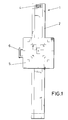
- Figure 1 corresponds to a front elevational view of the object of the invention, referring to an improved apparatus for radiological scanning, showing in a specific way, the display or screen, the supporting column, as well as the screen handle, and at the upper part of the column, the information digital display.
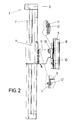
- Figure 2 shows a side elevational view, with the added detail of the union of the screen and the carriage with the possibility of an angular mobilization of same, as well as the supporting column and the sliding element fixed on it.
- Figure 3 shows the constitutive part of the intermediate carriage, this part being moved by means of an external lever, acting directly on a gas spring.
- Figure 4 corresponds to plan view thru the sectioned upper part of the object shown in figure 3.
- Figure 5 shows the supporting assembly of the bucky carrying inside an image carrier on which the bucky in the strict sense is moved.
- Figure 6 shows a side elevational view of the object represented in figure 5, and showing also the extractable support for performing radiological scannings on persons who cannot be in erect positions.
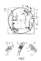
- Figure 7 shows a view thru the rear part of the object represented in figure 5, with the addition of three details corresponding to the pieces allowing thebucky support to turn 180o.
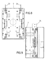
- Figure 8 shows a view of the rack-carriage sliding on the column.
- Figure 9 shows a side elevational view of the rack-carriage represented in figure 8.
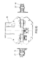
- Figure 10 corresponds to a view with marginal details of the toothed wheel support.
- Figure 11 shows an assembly of counterweights.
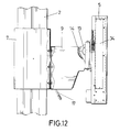
- Figure 12 shows a view of an optional embodiment of the invention, in which the bucky support is not fitted with the possibility of being horizontally positioned.
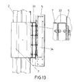
- FIG. 13 shows, lastly, an optional simplified embodiment of the invention.
- Figure 14 corresponds to a general perspective view of an optional embodiment of the invention.
- Figure 15 shows also a perspective view of the inner part of the body of the column devoid of the protecting plates which can adopt any configuration as considered appropiate, this view showing also the conductive and protecting body configuration of the different cables located inside the piping, so-called articulated piping, which is capable of being moved in a vertical ascending and descending sense in accordance with the performing of the toothed belts on the supporting element.
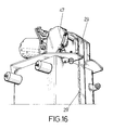
- Figure 16 shows a perspective view of the upper part of the column represented in figures 13 and 14, wherein the servomechanism fitted with the potenciometer can be seen.
- Figure 17 shows, lastly, a view similar to that represented in figure 16, thru the opposite side, and - showing also the potentiometer in the strict sense, as well as the circuit.
- the object of the invention related to an improved apparatus for radiological scannings (1), this being a graphic representation corresponding to a frontal view, implemented in figure 2, in which some parts thereof, partially sectioned, can be seen, this view showing also that the improved apparatus for radiological scanning (1) is formed starting from a column (2), covered by remplaceable plates which are fixed on the inner zone of the own column structure, where the elements aiding the raising and descent of the bucky (5), fitted with a handle (6), and capable of being mobilized in a circular sense until reaching 180o, and to this end the bucky (5) is fixed, thru its rear part, on an emerging support (9), constitutive of an intermediate carriage which is fixed, thru its rear part, on the rack-carriage (7), perimetrally fastened on the external surface of column (2), and fixed on the inner mechanisms thru elements which are inserted and fixed thru a longitudinal slot existing on a side of the column body (2), which is capable of allowing the covers to be rem
- the rack-carriage (7) is fixed on the intermediate carriage (9) by means of screws (12'), while the intermediate carriage (9) is fixed on the rear part of the bucky (5) by means of screws (12), in collaboration with an intermediate plate (11), supporting legs (10) emerging from the rear part of the bucky (5), which can facilitate the performing of a radiologist when he must carry out scannings on laying down or semi laying down patients, relaying also the rear part (5), and located between two articulated legs (10), on two projections (13), joining at the sides of the intermediate carriage (9), which has represented a graduated scale serving as an optical information means about the angulation required from the bucky (5).
- the graduated scale (14) is shown in figure 3, and the union of the emerging piece (13) and the intermediate carriage (9) is obtained by means of a cross element (15), inserted thru both sides of body (13), passing trough the intermediate carriage (9), at its emerging end, so obviously achieving the bucky (5) motion, on which the body (13) is fastened in a vertical ascending and descending sense, maintaining always a determinate angularity shown in the graduated scale (14), and, such as shown in figure 4, the motion is obtained starting from a lever (17), which, fastened on an articulation (18), acts by means of a gas spring, so obtaining the appropiate tilting of the bucky (5).
- Figure 4 shows that the piece or part (13) is parallel to a similar part (13'), receiving, in both cases, a supporting body of the intermediate carriage formed by the fixing and receiving elements (15) and (15'), respectively.
- Figure 5 shows in detail the support of the bucky with its handle (6), the figure 6 visualizing that the extendable legs (10) allow them to be extended outward, so configuring themselves like a supporting point of bucky (5) in the strict sense.
- Figure 7 shows the fact that the bucky body can be mobilized in a circular turn in accordance with a plurality of pulleys (21), superimposed on the rear part of the bucky, and in collaboration with a circular body (20) presenting a perimetric projection to be inserted in the central slot of pulleys (21), so that, when these pulleys are positioned in four equidistant points on their perimeter and on the own body (20), the mobilization in accordance with the handle (6) is simplified, the detail A-A indicating that at the inner part, the body (22) carrying the perimetric projection (20) is joined to the rear part of the bucky (5) by means the pulleys (21).
- FIGS 8 and 9 show that the rack-carriage (7) has two proyections or flanges (23) and (24), destined to facilitate their fixing.
- Figure 10 represents the support of the toothed wheels (26), fitted, at its central zone, with two circular pieces, fitted with a throat at its perimeter, each of the parts being referenced (27) and - (27'), while the throat is referenced in both cases (19).
- Figure 11 represents the couterweight assembly, which presents, at the upper part, two supporting pulleys (27) and (27'), on which the toothed belts (29) and (29') move, free of maintenance, the ends of which are fixed on flanges (30), and these, in turn, to be exact one of the flanges, are fixed, retaining the toothed belts (29) or (29'), to two angular pieces (32) and (32'), joined, in turn, by means of vertically located screws (31), to the - counterweight (28).
- Figure 12 corresponds to a graphic representation of an optional embodiment of the invention, in which the apparatus for radiological scannings (1) is not implemented with extensible legs (10), while in figure 13, it can be seen that, at option, la invention can be devoid of the intermediate carriage (9), the bucky (5) being directly fixed on the rack-carriage (7), intermedianting a plate (33), which is internally hollow, thru which the union of elements (5) and (7) is performed, and receiving, inside, the screw heads and nuts utilized to this purpose.
- the improved apparatus for radiological scanning (41) is constituted starting from incorporating in the external part of the supporting column, protecting plates (42), - which can adopt any configuration considered as appropiate, these plates covering the external zone of a supporting column presenting as a lower supporting link, a platform (45) fitted with conventional screws (48), which is located in a vertical sense in order to arrange the appropiate supporting means for the inner column, on which the toothed belts (29) and - (29') are moved, mobilizing the tube body (46) in this optional embodiment, outwardly located, which has an external zone (43) which is added to the covering piece surface (42), and by means of the appropiate retaining means, located on the belts (29) and (29'), it is achieved that the body (43) moves in a vertical ascending and descending sense through slots (44), located on the upper part, which are extended et the lower part thru slots (44') located next, but having
Landscapes
- Physics & Mathematics (AREA)
- Health & Medical Sciences (AREA)
- Engineering & Computer Science (AREA)
- Biomedical Technology (AREA)
- General Health & Medical Sciences (AREA)
- Medical Informatics (AREA)
- Nuclear Medicine, Radiotherapy & Molecular Imaging (AREA)
- Optics & Photonics (AREA)
- Life Sciences & Earth Sciences (AREA)
- General Physics & Mathematics (AREA)
- High Energy & Nuclear Physics (AREA)
- Molecular Biology (AREA)
- Spectroscopy & Molecular Physics (AREA)
- Measurement Of Radiation (AREA)
- Apparatus For Radiation Diagnosis (AREA)
- Radiography Using Non-Light Waves (AREA)
Applications Claiming Priority (4)
| Application Number | Priority Date | Filing Date | Title |
|---|---|---|---|
| ES9702535A ES2152794B1 (es) | 1997-12-05 | 1997-12-05 | Aparato para exploraciones radiologicas mejorado. |
| ES9702535 | 1997-12-05 | ||
| ES9802518A ES2153759B1 (es) | 1997-12-05 | 1998-12-01 | Mejoras introducidas en la patente de invencion n- 9702535/6, relativa a un aparato para exploraciones radiologicas mejorado. |
| ES9802518 | 1998-12-01 |
Publications (2)
| Publication Number | Publication Date |
|---|---|
| EP0927891A2 true EP0927891A2 (fr) | 1999-07-07 |
| EP0927891A3 EP0927891A3 (fr) | 2002-04-03 |
Family
ID=26155101
Family Applications (1)
| Application Number | Title | Priority Date | Filing Date |
|---|---|---|---|
| EP98500265A Withdrawn EP0927891A3 (fr) | 1997-12-05 | 1998-12-04 | Appareil à balayage radiologique amélioré |
Country Status (2)
| Country | Link |
|---|---|
| EP (1) | EP0927891A3 (fr) |
| HU (1) | HUP9802816A3 (fr) |
Cited By (4)
| Publication number | Priority date | Publication date | Assignee | Title |
|---|---|---|---|---|
| EP1536249A1 (fr) * | 2003-11-26 | 2005-06-01 | Swissray Medical AG | Dispositif servant à produire des images radioscopique en temps reel |
| US7753585B2 (en) | 2005-04-19 | 2010-07-13 | Swissray International Inc. | X-ray device having a column and having a cantilever arm displaceable on the column |
| WO2014129919A1 (fr) * | 2013-02-20 | 2014-08-28 | Закрытое Акционерное Общество "Импульс" | Montant pour déplacement vertical d'un appareil à rayons x |
| RU2567276C1 (ru) * | 2014-10-10 | 2015-11-10 | Закрытое Акционерное Общество "Импульс" | Стойка вертикального перемещения рентгеновского аппарата |
Family Cites Families (4)
| Publication number | Priority date | Publication date | Assignee | Title |
|---|---|---|---|---|
| US2220725A (en) * | 1940-11-05 | X-eay apparatus | ||
| US2276137A (en) * | 1940-06-14 | 1942-03-10 | Young Carl | X-ray bucky diaphragm support |
| SE463187B (sv) * | 1989-02-20 | 1990-10-22 | Ao Medical Products Ab | Saett vid och kassetthaallaranordning foer roentgen- eller liknande undersoekning |
| US5574767A (en) * | 1995-02-27 | 1996-11-12 | Hayes Technology, Inc. | Adjustable x-ray cassette holder |
-
1998
- 1998-12-04 EP EP98500265A patent/EP0927891A3/fr not_active Withdrawn
- 1998-12-04 HU HU9802816A patent/HUP9802816A3/hu unknown
Cited By (4)
| Publication number | Priority date | Publication date | Assignee | Title |
|---|---|---|---|---|
| EP1536249A1 (fr) * | 2003-11-26 | 2005-06-01 | Swissray Medical AG | Dispositif servant à produire des images radioscopique en temps reel |
| US7753585B2 (en) | 2005-04-19 | 2010-07-13 | Swissray International Inc. | X-ray device having a column and having a cantilever arm displaceable on the column |
| WO2014129919A1 (fr) * | 2013-02-20 | 2014-08-28 | Закрытое Акционерное Общество "Импульс" | Montant pour déplacement vertical d'un appareil à rayons x |
| RU2567276C1 (ru) * | 2014-10-10 | 2015-11-10 | Закрытое Акционерное Общество "Импульс" | Стойка вертикального перемещения рентгеновского аппарата |
Also Published As
| Publication number | Publication date |
|---|---|
| HUP9802816A3 (en) | 2002-11-28 |
| HU9802816D0 (en) | 1999-02-01 |
| EP0927891A3 (fr) | 2002-04-03 |
| HUP9802816A2 (hu) | 1999-11-29 |
Similar Documents
| Publication | Publication Date | Title |
|---|---|---|
| ES2413854T3 (es) | Lupa electrónica de escritorio | |
| JP5489613B2 (ja) | 放射線撮影システム | |
| US7648273B2 (en) | Radiation shielding for tomographic scanners | |
| EP2092890A1 (fr) | Table de fluoroscope aux rayons x et système de fluoroscope aux rayons x | |
| US20050058257A1 (en) | X-ray examination apparatus that is convertible among multiple examination configurations | |
| WO2016036037A1 (fr) | Table mobile pour projecteur | |
| EP0763343A1 (fr) | Chaîne de télévision à amplificateur d'image avec un ensemble arceau compact pour un système mobile d'imagerie à rayons X | |
| EP1457155A4 (fr) | Appareil de tomographie par ordinateur (ct) a rayons x | |
| EP0927891A2 (fr) | Appareil à balayage radiologique amélioré | |
| JP4488948B2 (ja) | X線ct撮影用ユニットおよびx線撮影装置 | |
| CN114072057A (zh) | Ct成像设备 | |
| JP3658010B2 (ja) | 医療用x線撮影装置 | |
| JPH11104128A (ja) | パノラマx線撮影装置用デジタルセンサカセット | |
| WO2014054899A1 (fr) | Dispositif d'imagerie par rayons x | |
| US5086448A (en) | X-ray examination unit | |
| KR20150102143A (ko) | 엑스레이 촬영용 디스플레이 수납장치 | |
| JP2017012409A (ja) | 乳房撮影装置 | |
| JP2000165778A (ja) | モニター装置の自在支持装置 | |
| JP4652887B2 (ja) | 患者支持装置および医用画像撮影装置 | |
| JP3023700U (ja) | X線撮影装置 | |
| JPH08252250A (ja) | 超音波診断装置 | |
| KR20060119463A (ko) | 족부 및 체형의 변위 측정 장치 | |
| CN211633212U (zh) | 一种口腔摄影辅助设备 | |
| EP0745891A2 (fr) | Appareil à rayons-X et arrangement pour l'indication de la position | |
| WO2015119468A1 (fr) | Dispositif d'imagerie par rayons x |
Legal Events
| Date | Code | Title | Description |
|---|---|---|---|
| PUAI | Public reference made under article 153(3) epc to a published international application that has entered the european phase |
Free format text: ORIGINAL CODE: 0009012 |
|
| AK | Designated contracting states |
Kind code of ref document: A2 Designated state(s): AT BE CH CY DE DK ES FI FR GB GR IE IT LI LU MC NL PT SE Kind code of ref document: A2 Designated state(s): AT BE DE FR GB IT NL PT SE |
|
| AX | Request for extension of the european patent |
Free format text: AL;LT;LV;MK;RO;SI |
|
| PUAL | Search report despatched |
Free format text: ORIGINAL CODE: 0009013 |
|
| AK | Designated contracting states |
Kind code of ref document: A3 Designated state(s): AT BE CH CY DE DK ES FI FR GB GR IE IT LI LU MC NL PT SE |
|
| AX | Request for extension of the european patent |
Free format text: AL;LT;LV;MK;RO;SI |
|
| AKX | Designation fees paid |
Free format text: AT BE DE FR GB IT NL PT SE |
|
| STAA | Information on the status of an ep patent application or granted ep patent |
Free format text: STATUS: THE APPLICATION IS DEEMED TO BE WITHDRAWN |
|
| 18D | Application deemed to be withdrawn |
Effective date: 20021005 |