EP0927918B1 - Vorrichtung zum Überwachen einer entlang eines vorgegebenen Weges bewegbaren Einrichtung sowie Modulatoreinheit und Auswerteeinheit für diese Vorrichtung - Google Patents
Vorrichtung zum Überwachen einer entlang eines vorgegebenen Weges bewegbaren Einrichtung sowie Modulatoreinheit und Auswerteeinheit für diese Vorrichtung Download PDFInfo
- Publication number
- EP0927918B1 EP0927918B1 EP98124873A EP98124873A EP0927918B1 EP 0927918 B1 EP0927918 B1 EP 0927918B1 EP 98124873 A EP98124873 A EP 98124873A EP 98124873 A EP98124873 A EP 98124873A EP 0927918 B1 EP0927918 B1 EP 0927918B1
- Authority
- EP
- European Patent Office
- Prior art keywords
- signal
- unit
- modulator
- modulation
- voltage
- Prior art date
- Legal status (The legal status is an assumption and is not a legal conclusion. Google has not performed a legal analysis and makes no representation as to the accuracy of the status listed.)
- Expired - Lifetime
Links
Images



Classifications
-
- H—ELECTRICITY
- H04—ELECTRIC COMMUNICATION TECHNIQUE
- H04B—TRANSMISSION
- H04B5/00—Near-field transmission systems, e.g. inductive or capacitive transmission systems
- H04B5/20—Near-field transmission systems, e.g. inductive or capacitive transmission systems characterised by the transmission technique; characterised by the transmission medium
- H04B5/24—Inductive coupling
-
- E—FIXED CONSTRUCTIONS
- E05—LOCKS; KEYS; WINDOW OR DOOR FITTINGS; SAFES
- E05F—DEVICES FOR MOVING WINGS INTO OPEN OR CLOSED POSITION; CHECKS FOR WINGS; WING FITTINGS NOT OTHERWISE PROVIDED FOR, CONCERNED WITH THE FUNCTIONING OF THE WING
- E05F15/00—Power-operated mechanisms for wings
- E05F15/40—Safety devices, e.g. detection of obstructions or end positions
- E05F15/42—Detection using safety edges
- E05F15/44—Detection using safety edges responsive to changes in electrical conductivity
-
- G—PHYSICS
- G05—CONTROLLING; REGULATING
- G05B—CONTROL OR REGULATING SYSTEMS IN GENERAL; FUNCTIONAL ELEMENTS OF SUCH SYSTEMS; MONITORING OR TESTING ARRANGEMENTS FOR SUCH SYSTEMS OR ELEMENTS
- G05B19/00—Program-control systems
- G05B19/02—Program-control systems electric
- G05B19/18—Numerical control [NC], i.e. automatically operating machines, in particular machine tools, e.g. in a manufacturing environment, so as to execute positioning, movement or co-ordinated operations by means of program data in numerical form
- G05B19/406—Numerical control [NC], i.e. automatically operating machines, in particular machine tools, e.g. in a manufacturing environment, so as to execute positioning, movement or co-ordinated operations by means of program data in numerical form characterised by monitoring or safety
- G05B19/4061—Avoiding collision or forbidden zones
-
- G—PHYSICS
- G05—CONTROLLING; REGULATING
- G05B—CONTROL OR REGULATING SYSTEMS IN GENERAL; FUNCTIONAL ELEMENTS OF SUCH SYSTEMS; MONITORING OR TESTING ARRANGEMENTS FOR SUCH SYSTEMS OR ELEMENTS
- G05B19/00—Program-control systems
- G05B19/02—Program-control systems electric
- G05B19/18—Numerical control [NC], i.e. automatically operating machines, in particular machine tools, e.g. in a manufacturing environment, so as to execute positioning, movement or co-ordinated operations by means of program data in numerical form
- G05B19/406—Numerical control [NC], i.e. automatically operating machines, in particular machine tools, e.g. in a manufacturing environment, so as to execute positioning, movement or co-ordinated operations by means of program data in numerical form characterised by monitoring or safety
- G05B19/4062—Monitoring servoloop, e.g. overload of servomotor, loss of feedback or reference
-
- G—PHYSICS
- G05—CONTROLLING; REGULATING
- G05B—CONTROL OR REGULATING SYSTEMS IN GENERAL; FUNCTIONAL ELEMENTS OF SUCH SYSTEMS; MONITORING OR TESTING ARRANGEMENTS FOR SUCH SYSTEMS OR ELEMENTS
- G05B23/00—Testing or monitoring of control systems or parts thereof
- G05B23/02—Electric testing or monitoring
- G05B23/0205—Electric testing or monitoring by means of a monitoring system capable of detecting and responding to faults
- G05B23/0218—Electric testing or monitoring by means of a monitoring system capable of detecting and responding to faults characterised by the fault detection method dealing with either existing or incipient faults
- G05B23/0224—Process history based detection method, e.g. whereby history implies the availability of large amounts of data
- G05B23/0227—Qualitative history assessment, whereby the type of data acted upon, e.g. waveforms, images or patterns, is not relevant, e.g. rule based assessment; if-then decisions
-
- E—FIXED CONSTRUCTIONS
- E05—LOCKS; KEYS; WINDOW OR DOOR FITTINGS; SAFES
- E05Y—INDEXING SCHEME ASSOCIATED WITH SUBCLASSES E05D AND E05F, RELATING TO CONSTRUCTION ELEMENTS, ELECTRIC CONTROL, POWER SUPPLY, POWER SIGNAL OR TRANSMISSION, USER INTERFACES, MOUNTING OR COUPLING, DETAILS, ACCESSORIES, AUXILIARY OPERATIONS NOT OTHERWISE PROVIDED FOR, APPLICATION THEREOF
- E05Y2900/00—Application of doors, windows, wings or fittings thereof
- E05Y2900/10—Application of doors, windows, wings or fittings thereof for buildings or parts thereof
- E05Y2900/104—Application of doors, windows, wings or fittings thereof for buildings or parts thereof for elevators
-
- G—PHYSICS
- G05—CONTROLLING; REGULATING
- G05B—CONTROL OR REGULATING SYSTEMS IN GENERAL; FUNCTIONAL ELEMENTS OF SUCH SYSTEMS; MONITORING OR TESTING ARRANGEMENTS FOR SUCH SYSTEMS OR ELEMENTS
- G05B2219/00—Program-control systems
- G05B2219/30—Nc systems
- G05B2219/37—Measurements
- G05B2219/37633—Output modulated signal on detection of blocking instead of flat signal
Definitions
- the invention relates to a device for monitoring a preferably movable along a predetermined path means, such as a rolling, sliding gate or an elevator door.
- the apparatus includes a signal generator for generating a fixed frequency carrier signal.
- a modulation signal for modulating the carrier signal is generated, for example, depending on the switching state of at least one switch arranged in the predetermined path.
- An electrical coupling device is arranged between the modulator unit and an evaluation device for evaluating the modulated carrier signal.
- the device preferably includes a switching device that switches a drive device for moving the movable device to be effective or ineffective.
- the pulse width of the modulation signal is changed depending on the state of the two switches in the modulator unit. If neither of the two switches is closed, then the pulse-pause ratio is 1: 1. If one or the other switch is closed, then the pulse-pause ratio is either 1: 3 or 3: 1.
- An operating state in which both switches are closed and can be evaluated separately is not provided in the known device.
- the known device has a circuit complex modulator unit; because the different pulse-pause ratios can be realized only with a relatively large amount of circuitry. The evaluation is also expensive in the known device, so that a computer circuit must be used to detect the various Puts-pause ratios.
- the modulator unit is constructed so that the carrier signal is not modulated at a deviating from the predetermined sensor signal sensor signal.
- the evaluation unit When the unmodulated carrier signal is detected, the evaluation unit generates a second monitoring signal deviating from the first monitoring signal.
- the states modulation ON and modulation OFF are used in the invention to determine whether an obstacle is in the path of the movable device.
- the invention is based on the recognition that it is easier to determine whether a modulation is present or not than to determine a pulse-pause ratio. Therefore, the carrier signal is modulated only in a state of the switch, e.g. in the normal state of the switch, indicating that there is no person or object in the given path.
- the evaluation unit detects the modulation and outputs the first monitoring signal to the control device.
- the control device recognizes on the basis of the first monitoring signal that the drive device can continue to be operated. If the switch encounters a person or an object, it switches to a holding position which indicates that the movement of the goal should be stopped. The switching of the switch in the holding position has the consequence that the carrier signal is no longer modulated.
- the evaluation device detects the unmodulated carrier signal and generates the second monitoring signal, whereupon the drive device is stopped.
- the device according to the invention is already advantageously used in a single sensor unit.
- the circuit complexity for the not necessarily required modulation is an advantage over that manual setting of the operating point of the evaluation can be omitted. This adjustment is required without modulation because, depending on the length of the movable device in the coupling device damping of the signal coming from the sensor unit occurred.
- the evaluation unit can determine in a very large operating range whether the carrier signal is modulated or unmodulated.
- the electrical coupling device on the side of the evaluation unit includes a first inductance and on the side of the modulator unit, a second inductance.
- a conductor loop running along the predetermined path preferably couples the two inductances.
- two modulator units are used which modulate the carrier signal with different frequencies.
- the connections of switching strips or optical sensors to the modulator units can be short in this arrangement, when the modulator units are arranged in the vicinity of the sensors. In a roll-up door it is avoided that long connecting cables have to be drawn through the door spar of the roller shutter.
- the modulator units have the same power requirement. If the modulator units are fed, for example, from the carrier signal, it is ensured by the same power requirement that both modulator units have the same supply voltage. With essentially the same construction of the modulator units, the signals demodulated in the evaluation circuit then have the same amplitude values.
- the signal generator includes an output stage of greater output power, preferably a push-pull output stage.
- the carrier signal can be used by this measure to power the modulator unit or the modulator units.
- several modulator units can draw their supply voltage from the carrier signal due to the high power.
- Several Modulatorüen can be connected without much effort in series, if they are arranged with the help of other bobbin on the steel cable.
- the modulator units contain a terminating element which is effectively switched on when the modulation is switched off by means of a circuit device on the side of the coupling device.
- a resistor is used to match, so sized is that the modulator unit receives the same supply voltage regardless of the presence of a modulation or the lack of modulation. If the modulator unit is in the OFF state, the supply power of the other modulator unit would be lower without the addition of the terminating element. If the supply voltage is too small, this modulator unit becomes inoperative. This is prevented by the connection of the terminating element.
- the modulator unit can be designed in a small space. If the signal generator is located on the side of the evaluation unit, then in the case of a coupling device operating according to the transformer principle, the modulator unit can also be fed directly from the carrier signal transmitted via the coupling device without an additional voltage source. A connection of the modulator unit to a mains voltage or the supply of constantly changing batteries deleted.
- the modulator unit contains an overlay device for superimposing a plurality of modulation signals.
- the modulation signals preferably have a rectangular waveform.
- the frequency of the modulation signals is different for each sensor unit.
- the evaluation unit contains a demodulator which separates the modulation signal or the superimposed modulation signals from the carrier signal.
- a demodulator which separates the modulation signal or the superimposed modulation signals from the carrier signal.
- a synchronizing circuit which outputs a predetermined output signal upon detection of a specific modulation frequency.
- phase locked loop phase locked loop
- a digital filter circuit is used in another development.
- digital filters lets to avoid the synchronization of synchronizing, which requires a lot of time.
- the evaluation unit contains a comparison unit for comparing the voltage values at their inputs.
- a clamp circuit depending on the switching state of the switch modulated or unmodulated carrier signal.
- the comparison unit can also be replaced by a transistor.
- a reference signal At the other input of the comparison unit is a reference signal.
- the output of the comparison unit is connected to a signal-shaping unit which generates a switching signal for controlling the switching unit.
- the signal-shaping unit can essentially be constructed with two monostable multivibrators. The result is an evaluation circuit that contains only a few components.
- the evaluation unit generates the second monitoring signal or a third monitoring signal when the carrier signal is no longer detected.
- the evaluation unit also takes into account the functionality of the coupling device, the modulator unit and the signal generator in addition to the sensor signal of the sensor unit. If one of these modules fails, this is reported by the evaluation unit.
- the second monitoring signal is e.g. used to stop a movement of the movable device.
- the second or third monitoring signal additionally actuates, for example, an optical or acoustic warning device.
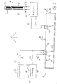
- FIG. 1 shows a block diagram of a device 10 for stopping a roll-up gate 12 shown schematically, which, for example, closes the exit of a property.
- the roller shutter 12 shown in plan view is movable in the two directions indicated by a double arrow 14 by means of a drive device, not shown.
- a switching strip 16 is arranged in the exit.
- the switching strip 16 contains conductive buttons 18 and 20, which are compressed by a force F, if the roller door when closing encounters an obstacle.
- the switching strip 16 is connected to terminals 21 a and 21 b with a modulator 44, which will be explained below.
- the roller shutter 12 opens or closes when a start switch mounted near the door is manually operated. Alternatively or additionally, the operation of the door can also be caused by means of a remote control. After opening, the roller shutter 12 remains open for a predetermined time, for example, so that a vehicle can pass. After the predetermined time, the roller shutter 12 closes automatically. If there is still a vehicle or a person in the exit at this time, the force F is generated as soon as the goal hits the person or the object. With the circuit shown in Figure 1, the automatic closing of the roller shutter 12 is interrupted when closing the buttons 18 and 20 until the buttons 18 and 20 return to their rest position and a new startup process is performed.
- a steel cable 24 is stretched, which forms a conductor loop 26 together with the conductive gate body 22.
- the steel cable 24 passes through the ring centers of two annular coils 28 and 30.
- the toroidal coil 28 is arranged stationary, so that the steel cable 24 moves in a movement of the roller shutter 12 without contact through the annular coil 28 therethrough.
- the annular coil 30 moves as well as the switching strip 16 with the roller shutter 12th
- the toroidal coil 28 has a core 32 around which the turns of a winding 34 run. One end of the winding 34 is connected to a ground line M. The other end of the winding 34 is connected to the one terminal of a matching resistor 36. The other terminal of the matching resistor 36 is connected to the output of a signal generator 38.
- a sinusoidal primary signal PS is generated with a carrier frequency of, for example, 10 kHz, cf. also FIG. 4.
- the ring coil 30 has on a core 40 also turns a winding 42.
- the two ends of the winding 42 are short-circuited in the modulator 44 in the cycle of a modulation frequency f1, for example, 1 kHz, if the switching strip 16 is in its normal state in which the buttons 18 and 20 do not touch and in which the circuit is closed by the switching strip 16 and with a load resistor 50.
- a modulation frequency f1 for example, 1 kHz
- the ring coils 28 and 30 and the conductor loop 26 form a transformer U, via which the modulator 44 acts on the primary signal PS and generates an evaluation signal AS on the ring coil 28.
- At the toroidal coil 30 is a secondary signal SS.
- the modulator 44 modulated in the normal state of the switching strip 16, the primary signal PS, so that a modulated secondary signal SS is generated, see. Also FIG. 4.
- An evaluation circuit 46 detects whether the evaluation signal present at its input is modulated by the modulator 44. If this is the case, then a voltage is output at an output A1, which holds a relay 108 shown in Figure 3 in its working state. In the working state, the drive device of the roller shutter 12 is effective.
- the primary signal PS is no longer modulated.
- the unmodulated primary signal PS is present as an evaluation signal AS.
- the evaluation circuit 46 detects the lack of modulation and outputs at the output A1 a voltage of plus 12 volts.
- the relay 108 at the output of the evaluation circuit 46 drops and interrupts, for example, the power supply to the drive means of the roller shutter 12, so that the roller shutter 12 stops.
- a high-impedance load resistor 50 connects the buttons 18 and 20 of the switching strip 16. If the load resistor 50 is no longer effective due to an interruption in the buttons 18 or 20 itself or in the leads to the modulator 44, the modulation is set in the modulator 44. By this measure, a malfunction of the device 10 is prevented.
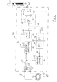
- FIG. 2 shows a block diagram of the modulator 44.
- the secondary signal SS is rectified by means of a bridge rectifier 51.
- modulator element 52 With one below even closer explained modulator element 52, the rectified secondary signal GS can be shorted to ground. This short circuit has a direct effect on the toroidal coil 30 via the rectifier 51. Finally, the connections of the winding 42 are short-circuited by the modulator element 52.
- the rectified secondary signal GS is fed in the modulator 44 to a stabilizing circuit 54, which generates a sufficiently stable supply voltage Uc regardless of whether the rectified secondary signal GS is modulated or unmodulated. An additional power supply of the modulator 44 by a battery or a power supply is thus eliminated.
- the modulator 44 includes a multivibrator 56 which generates a ramp voltage US at a frequency of 2 kHz.
- the exact course of the sawtooth voltage US is explained below with reference to FIG.
- the sawtooth voltage US is applied to the negative input of a working as a comparator operational amplifier 58.
- a positive reference voltage Vref is generated by means of a voltage divider comprising a resistor R1 and the load resistor 50, which has approximately the mean value of the sawtooth voltage US.
- the voltage at the positive input of the operational amplifier 58 deviates from the reference voltage Vref when the switching strip 16 is actuated or when an interruption of the circuit formed by the switching strip 16 and the load resistor 50 occurs. Therefore, the actual voltage at the positive input of the operational amplifier 58 is referred to as voltage U1, cf. also FIG. 5.
- the output of the operational amplifier 58 is connected via a line 60 to a flip-flop 62.
- the voltage at the output of the operational amplifier 58 is referred to as U2, cf. Also Figure 5.
- U2, cf. Also Figure 5.
- U3 At the output of the flip-flop 62 is a rectangular voltage U3, see. also Figure 5.
- the voltage U3 has effective modulation only a frequency of 1 kHz, because the flip-flop 62 operates as a divider.
- the output of the flip-flop 62 is connected to the input of a flip-flop 64, so that the two flip-flops 62 and 64 are connected in series.
- At the output of the flip-flop 64 creates a voltage U4, see. Also Figure 5.
- the output of the flip-flop 64 is connected directly to the modulator element 52.
- the flip-flops 62 and 64 are connected so that the voltage U4 is rectangular only when the switching strip 16 is in its normal state. Is the safety edge 16 is pressed or the circuit is interrupted by the switching strip 16, the voltage U4 has the value 0 volts, and the modulator element 52 does not switch. This means that no modulation of the secondary signal SS occurs in these cases. Due to the coupling by means of transformer Ü, cf. FIG. 1, no modulation of the evaluation signal AS occurs at the evaluation circuit 46, cf. FIG. 1
- FIG. 3 shows a block diagram of the evaluation circuit 46.
- the evaluation signal AS is applied to the positive input of a comparator 100 with the interposition of a clamping circuit, not shown. Such clamping circuits are known from television technology. Their job is to create a voltage swing.
- the evaluation signal AS thus raised has a voltage curve U5, cf. also Figure 6.
- the negative input of the comparator 100 is connected to the ground line M. At the output of the comparator 100 is a voltage U6, see. FIG. 6.
- the mode of operation of the comparator 100 will also be explained below with reference to FIG.
- the output of the comparator 100 is connected to the input of a first monoflop 102, which switches its output to H level with a falling clock edge until a predetermined switching time has elapsed, which corresponds approximately to the period of the primary signal PS with the frequency of 10 kHz, ie about 100 ⁇ s.
- a voltage curve U7, cf. FIG. 6 At the output of the monoflop 102 there is a voltage curve U7, cf. FIG. 6.
- the output of the monoflop 102 is connected to the input of a monoflop 104, which also switches the output to H level with a falling clock edge at its input.
- the switching time of the monoflop 104 corresponds approximately to the period of the modulation signal of 1 kHz, i. a time of about 1 ms.
- a voltage curve is formed, which is explained in more detail below with reference to FIG.
- the inverting output A1 of the monoflop 104 with a voltage curve U8, cf. FIG. 6 is connected to one terminal of an armature coil 106 of the relay 108.
- the other terminal of the armature coil 106 is connected to the positive operating voltage of the evaluation circuit 46. If the inverting output A1 of the monoflop 104 has an L level, ie 0 volt, then a normally open contact 110 closes a working circuit 112, which connects the drive device of the roller shutter 12, cf. figure 1, effectively switches. On the other hand, if the inverting output A1 of the monoflop 104 has an H level, the normally open contact 110 is open. The drive device of the roller shutter 12 and thus also the movement of the roller shutter 12 itself are stopped.
- evaluation signal AS is no longer modulated. This is the case when the safety edge 16, cf. 1, the circuit is interrupted by the switching strip 16 or when the transformer Ü or the modulator 44 operates incorrectly.
- the evaluation signal AS is also not modulated when due to a defective signal generator 38, the primary signal PS is not generated.
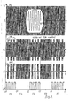
- FIG. 4 shows signal curves in the circuit according to FIG. 1, so that reference is also made to FIG. 1 when explaining FIG.
- FIG. 4 shows, in the order from top to bottom, the voltage curves of the primary signal PS, the evaluation signal AS, the secondary signal SS and the voltage U4, cf. FIG. 2.
- the voltage values U of the voltage profiles are each plotted on a common ordinate axis 113. On the abscissa axes in each case the time t is removed.
- the primary signal PS is a sine signal with a frequency of 10 kHz, cf. the magnification PS *.
- the evaluation signal AS is generated by modulation.
- the evaluation signal AS is shown in the second coordinate system from above in FIG.
- the evaluation signal AS has a carrier frequency of 10 kHz, which is modulated with the modulation frequency of 1 kHz.
- the degree of modulation is about 40%, due to the damping effect in the transformer Ü, see. FIG. 1.
- the modulation leads to a temporary reduction in the amplitude of the carrier signal, cf. Modulation gaps 114.
- the secondary signal SS is shown in a coordinate system below the coordinate system for the evaluation signal AS.
- the degree of modulation is about 100%.
- the carrier signal of the secondary signal SS with a frequency of 10 kHz is therefore cut in synchronism with the modulation frequency of 1 kHz in its amplitude to about 0 volts. This creates modulation gaps 116.
- a voltage curve U4 in the lowest coordinate system of FIG. 4 shows the voltage at the modulator element 52 or at the output of the flip-flop 64 for a better understanding, cf. FIG. 2. It is modulated as soon as the voltage at the output of the flip-flop 64 has a high voltage value. If the voltage U4 is at the value 0 volts, no modulation takes place.
- time period T1 starts at a time t0 and ends at a time t1.
- time period T1 the time periods T2 to T5 follow in this order.
- the time period T2 thus begins at time t1.
- the time periods T3, T4 and T5 start at times t2, t3 and t4, respectively.
- the device 10 operates to stop the roller shutter 12 in its normal mode in which no force F acts on the switching strip 16 and in which the circuit formed by the switching strip 16 is closed.
- the modulator 44 modulates the evaluation signal AS.
- the circuit is interrupted by the switching strip 16, because, for example, a connection line of the switching strip 16 has been interrupted by the weather.
- the interruption leads, as explained below with reference to FIG 5, to a lack of modulation.
- the absence of the modulation of the evaluation signal AS is detected in the evaluation circuit 46.
- the roller shutter 12 is stopped if it is in motion. Actuation of the roller shutter 12 is not possible if the modulation of the evaluation signal AS is missing.
- the force F produced by an obstacle actuates the properly connected switching strip 16. As explained below with reference to FIG. 5, this actuation likewise leads to a lack of modulation.
- the evaluation circuit 46 the omission of the modulation of the evaluation signal AS is detected and the movement of the roller shutter 12 is stopped before the obstacle. An actuation of the roller shutter 12 is only possible again when the force F no longer acts on the switching strip 16, i. the obstacle has been removed from the gate exit.
- FIG. 5 shows signal curves in the modulator 44, so that reference is also made to FIG. 2 when explaining FIG.
- Figure 5 are five coordinate systems shown with a common ordinate axis 120, on each of the voltage values U are removed.
- the time t is plotted on the abscissa axes of the coordinate systems.
- the times t0 to t4 again designate the boundaries between the time periods T1 to T5.
- Lines 122 illustrate the boundaries between periods T1 through T5.
- the sawtooth voltage US is shown in the uppermost coordinate system of Figure 5.
- the mean value of the sawtooth voltage US is at half the supply voltage Uc.
- the ramp voltage US varies between a lower voltage value at about one third of the supply voltage Uc and an upper voltage value at about two thirds of the supply voltage Uc.
- the sawtooth voltage US has the same signal curve in all time segments T1 to T5.
- a horizontal line 124 illustrates the value of the reference voltage Vref, which in the exemplary embodiment is at half the supply voltage Uc.
- a horizontal line 126 illustrates a voltage value which corresponds to one third of the supply voltage Uc.
- a horizontal line 128 finally illustrates a voltage value which corresponds to two thirds of the supply voltage Uc.
- the voltage U1 coincides with the reference voltage Vref, which specifies the desired value for the voltage U1 in the normal mode.
- the operational amplifier 58 compares, as already mentioned, the voltage value U1 with the constantly changing voltage values of the sawtooth voltage US. As long as the voltage value U1 in the time intervals T1, T3 and T5 is within the voltage range in which the voltage values of the ramp voltage US move, a rectangular signal is generated at the output of the operational amplifier 58, which is shown in the middle coordinate system of Figure 5 as a voltage waveform U2 , In the row sections T1, T3 and T5, the voltage U1 is 1/2 Uc, so that the pulse width of the rectangular signal of the voltage U2 is equal to the time for the pulse pause.
- the voltage U1 has a value which is above the voltage which corresponds to two-thirds of the supply voltage Uc.
- the voltage at the positive input of the operational amplifier 58 is permanently greater than the voltage values of the sawtooth voltage US at the negative input of the operational amplifier 58.
- the result is that the output of the operational amplifier 58 and thus also the voltage U2 permanently to a high voltage value, for example plus twelve volts lies.
- the voltage value U1 is pulled by pressing the switching strip 16 below a voltage value which corresponds to one third of the supply voltage Uc.
- the voltage value at the positive input of the operational amplifier 58 is permanently smaller than the voltage values of the sawtooth voltage at the negative input of the operational amplifier 58. Therefore, the voltage value 0 volts is output at the output of the operational amplifier 58 until the switching strip 16 is released again at the time t4.
- the effect of the flip-flop 62 on the voltage curve U2 is shown in a coordinate system for the voltage U3.
- the flip-flop 62 divides the clock frequency of the rectangular voltage U2 in the case of modulation, i. in the periods T1, T3 and T5. In the time periods T2 and T4, the signal curve predetermined by the voltage U2 is substantially maintained.
- the voltage U4 at the output of the flip-flop 64 is shown.
- the flip-flop 64 is connected so that the switching frequency is maintained at its input at the output.
- a permanent positive voltage value of the voltage U4 is suppressed. Consequently, the voltage U4 in the periods T1, T3 and T5 has a rectangular Signalver running.
- the voltage U4 has the voltage value 0 volts. Therefore, the modulator element 52 is not driven in the periods T2 and T4, so that the modulation of the secondary signal SS, the rectified secondary signal GS and the evaluation signal AS is omitted.
- FIG. 6 shows signal curves in the evaluation circuit 46, so that reference is also made to FIG. 3 when explaining FIG.
- FIG. 6 shows six coordinate systems with a common ordinate axis 140 on which Voltage values U are removed.
- the coordinate systems each have an axis of abscissa on which the time t has been removed.
- Lines 142 illustrate the boundaries between periods T1 through T5.
- the voltage U5 is shown, which is generated by means of the clamping circuit at the positive pole of the comparator 100.
- the clamping circuit causes the voltage U5 to be raised in comparison with the voltage values of the evaluation signal AS.
- the voltage U5 is raised so that even with a low degree of modulation, the lower envelope of the voltage U5 contains negative voltage peaks 144, between which lie regions with positive lower amplitude values.
- the mean coordinate system in Figure 6 shows the voltage U6 at the output of the comparator 100.
- the negative input of the comparator 100 is connected to the ground line M. Therefore, the voltage spikes 144 cause the voltage at the output of the comparator 100 to drop from the voltage value plus 12 volts to the 0 volt level. Falling signal edges occur in the voltage curve of the voltage U6 whenever the voltage U5 transitions from the positive voltage range to the negative voltage range, as is the case with the voltage peaks 144.
- a coordinate system for the voltage U7 at the output of the comparator 100 downstream monoflop 102 is shown below the coordinate system for the voltage U6, a coordinate system for the voltage U7 at the output of the comparator 100 downstream monoflop 102 is shown.
- the monostable 102 switches with a falling edge at its input for a time which corresponds approximately to the period of the carrier signal, ie at a carrier frequency of 10 kHz results in a period of 100 microseconds. Rectangular pulses 146 therefore arise from several immediately successive switching operations of the monoflop 102 where the voltage peaks 144 occur.
- the output of the monoflop 102 is permanently at a high positive voltage value in the periods T2 and T4 due to the wide voltage peak 144 occurring there, cf.
- Reference numerals 148 and 150 are used to the output of the monoflop 102.
- the voltage U8 at the inverting output of the monoflop 102 downstream monoflop 104 is shown.
- the monoflop 104 also switches with falling signal edges.
- the switching time of the monoflop 104 coincides approximately with the period of 1 ms of the modulation signal, i. a signal with a frequency of 1 kHz.
- the gaps between the square pulses 146 are closed due to immediately successive switching operations of the monoflop 104.
- a high positive voltage value is present in the time periods T1, T3 and T5, for example plus 12 volts. Due to the inversion in the time segments T1, T3 and T5, the voltage value 0 V is present at the inverting output.
- This voltage value causes due to the wiring shown in Figure 3 of the relay 108 that the relay 108 is turned on and the normally open contact 110 is closed.
- the roller shutter 12 can thus be operated.
- FIG. 7 shows a block diagram of a device 10 'for actuating a roll-up door 12' shown in plan view.
- FIG. 7 corresponds essentially to FIG. 1, so that assemblies having the same function will not be explained again. However, these modules are given a superscript to distinguish.
- a switching strip 16 'or 16 is fastened to the longitudinal sides of the roller shutter 12' in each case The switching strips 16 'and 16" are essentially constructed like the switching strip 16.
- the switching strip 16 " like the switching strip 16 ', is connected to the modulator 44', see also connections 21a ', 21b' and 21a" and 21b ".
- the signal generator 38 ' is constructed like the signal generator 38, cf. FIG. 1.
- the construction of the modulator 44 ' will be explained in greater detail below with reference to FIG.
- the evaluation circuit 46 ' has in addition to the output A1' still another output A2.
- the output A1 ' is used to actuate the drive device, not shown, of the roller shutter 12' depending on the switching state of the switching strip 16 '.
- the output A2 in contrast, serves to actuate the drive device of the roller shutter 12 'depending on the switching state of the switching strip 16 ".
- the evaluation circuit 46 detects the respective modulation state of the evaluation signal AS' and actuates the drive device of the roller shutter 12 'so that a safe operation of the roller shutter 12' is ensured.
- the structure of the evaluation circuit 46 ' is explained in more detail below with reference to FIG.
- FIG. 8 shows a block diagram of the modulator 44 '.
- Assemblies in the modulator 44 'having the same function as in the modulator 44 of Figure 3 have the same reference numeral in Figure 2, but with a superscript stroke and in the case of the double superscript stroke.
- the modulator 44 ' contains for both switching strips 16 ', 16 "together a rectifier 51', a modulator element 52 'and a stabilizing circuit 54'.
- a to the switching strip 16 'belonging multivibrator 56' generates a PSD harness US 'with a frequency of 2 kHz.
- an operational amplifier 58' and a flip-flop 62 ' are used which operate as explained above with reference to the operational amplifier 58 and the flip-flop 62.
- Another multivibrator 56 "generates a sawtooth voltage US” with a frequency of 1.6 kHz, which is compared in an operational amplifier 58 "with a voltage U1" at the terminal 21a "of the switching strip 16".
- the output of the operational amplifier 58 is connected to the input of a flip-flop 62".
- the modulator 44 ' is a modulator with two modulation channels.
- the two voltages U3 'and U3 are applied to the inputs of a NOR gate 160 which combines the voltage values at its inputs according to a NOR function.
- a voltage V10 has a positive value only if a voltage of 0 volts is applied to both inputs of the gate 160.
- the voltage U10 acts directly on the modulator element 52.
- the modulator element 52 switches the winding 42' retroactively via the rectifier 51 'to the secondary signal SS' and in order to also modulate the evaluation signal AS ', see also FIG.
- the voltages U2 'and U2 "continue to be applied to the inputs of a blocking circuit 162 which causes the modulator element 52' to be driven no longer than a predetermined time, for example half the clock period of the 800 kHz modulation clock Locking circuit 164 ensures the modulator element 52 'also works correctly during the switch-on process.
- FIG. 9 shows a block diagram of the evaluation circuit 46 '.
- the evaluation signal AS ' is applied to the input of a demodulator circuit 170 in the evaluation circuit 46'.
- a voltage U11 At the output of the demodulator circuit 170 is a voltage U11, the course of which will be explained in more detail below with reference to FIG 11.
- the demodulator circuit 170 includes a rectifier.
- the demodulator circuit 170 is followed by a filter circuit 172. At the output of the filter circuit 172, a voltage U12 is applied, the voltage curve of which essentially follows the modulation curve in the evaluation signal AS '.
- a tone with a frequency of 1 kHz in the voltage waveform U12 is detected. If a tone with a frequency of 1 kHz is detected by the tone decoder 174, the voltage value 0 volts is generated at the output A1 '. The relay 108 'picks up and closes the make contact 110'. Thus, the normal mode of the safety edge 16 'is detected and the roller shutter 12' can be operated. If the sound at a frequency of 1 kHz in the evaluation signal AS 'is not detected by the sound decoder 174, the output A1' is at a voltage of plus 12 volts. The relay 108 'drops and opens the normally open contact 110'. The roller shutter 12 'can not be operated when either the switching strip 16' is pressed or when the circuit is interrupted by the switching strip 16 '.
- the voltage U12 is also applied to the input of a tone decoder 176, which detects a tone of 800 Hz. If such a tone is present in the evaluation signal AS 'and thus also in the voltage curve of the voltage U12, the output of the tone decoder 176 has a voltage value of 0 volt. Thus, the relay 108 "pulls on and closes the normally open contact 110". The roller shutter 12 'can in turn be operated. If, on the other hand, a 800 Hz tone is missing, the output of the tone decoder 176 is at a voltage of plus 12 volts. The relay 108 "opens the normally open contact 110". The roller shutter 12 'can not be operated when either an obstacle on the switching strip 16 "presses, or the circuit is interrupted by this switching strip 16".
- Both normally open contacts 110 'and 110 are closed when the switching strip 16' and the switching strip 16" are in their normal operating mode. Will the evaluation signal AS 'is not modulated at all, both working contacts 110' and 110 "are opened, this being the case, for example, when the transformer Ü ', see FIG. 7, or the modulator 44' is not working properly.
- the evaluation circuit 46 ' also includes an error detection 180.
- a connected to the error detection LED 182 only lights up when the evaluation circuit 46' detects a modulated evaluation signal AS '.
- the error detection 180 is similar to the evaluation circuit 46 explained with reference to FIG.
- FIG. 10 shows signal curves in the modulator 44 ', so that reference is made to FIG. 8 when explaining FIG. FIG. 10 shows four coordinate systems with a common ordinate axis 188 on which voltage values U are plotted. The time t is plotted on the abscissa axes of the coordinate systems.
- Both of the switching strips 16 'and 16 are in their normal operating mode during periods T10, T12 and T14 During a period T11, the switching strip 16' is pressed and the switching strip 16" is in its normal operating mode. In a period of time T13, however, only the switching strip 16 "is pressed and the switching strip 16 'is in its normal operating mode.
- the uppermost coordinate system in Figure 10 shows the voltage waveform of the voltage U3 'at the output of the flip-flop 62'.
- rectangular pulses 190 are generated. If the switching strip 16 'is pressed in the time interval T11 or if the circuit is interrupted by the switching strip 16', then the voltage U3 'remains permanently at the voltage value 0 volt, cf. Pulse gap 192. If the switching strip 16 'released again, so the voltage U3' again has a rectangular waveform, see. Rectangular pulses 194.
- the rectangular pulses 190 and 194 have a pulse frequency of 1 kHz.
- a coordinate system for the voltage U10 is shown, whose waveform is a NOR operation of the waveforms for the voltages U3 'and U3".
- the voltage U10 has a high positive value only if both voltages U3 'and U3 "have the voltage value 0.
- the voltage U10 has a rectangular waveform with square pulses 210 having different pulse widths. In this context, also spoken by a rectangular course with random pulse width. However, the pulse width is not greater than the pulse width of the rectangular pulses 200 and 204.
- the course of the evaluation signal AS ' is shown in the lowest coordinate system of FIG.
- the evaluation signal AS ' has been shown in FIG. 10 for the sake of completeness. It does not occur in the modulator 44 'but rather on the evaluation unit 46'.
- the evaluation signal AS' is modulated at 1 kHz and at 800 Hz During the time interval T11 in which only the switching strip 16 'is pressed is, the evaluation signal AS 'is modulated only with the frequency 800 Hz In the period T13, in which only the switching strip 16 "is pressed, the evaluation signal AS', however, is modulated only with the frequency of 1 kHz.
- FIG. 11 shows signal curves in the evaluation unit 46 ', so that reference is also made to FIG. 9 when explaining FIG.
- FIG. 11 shows three coordinate systems which have a common ordinate axis 220. On the ordinate axis 220 voltage values U are removed.
- the coordinate systems in FIG. 11 each have their own abscissa axis, on which the time t is plotted.
- the curve of the voltage U12 is shown.
- the filter 172 Through the filter 172, the high-frequency component of 10 kHz was filtered out of the voltage curve U11.
- the course of the voltage U12 essentially follows the envelope of the voltage curve U11.
- both tone decoders 174 and 176 detect their respective calibration frequencies of 1 kHz and 800 Hz, respectively.
- the tone decoder 176 detects its calibration frequency of 800 Hz.
- the tone decoders 174 and 176 are synchronizing circuits that want to synchronize to their calibration frequencies. Once a sufficiently stable synchronization is present, the output of the sound decoder 174 or 176 is switched. In the sound decoders 174 and 176 so-called phase control circuits are included, English referred to as "phase locked loop".
- FIG. 12 shows a block diagram of a device 10a for stopping a roll-up door 12a.
- the device 10a differs from the device 10 'explained above with reference to FIG. 7 in that not one modulator 44' but two modulators 44a and 44b are used.
- On the longitudinal sides of the roller shutter 12a each a switching strip 16a and 16b is attached.
- the switching strip 16a or 16b is constructed like the switching strip 16 'or 16 "The switching strip 16a is connected to the modulator 44a, which modulates the primary signal PS with a frequency of 1 kHz For this purpose, the modulator 44a is connected by means of an annular coil 30a
- the signal generator 38a generates a higher power primary signal PSa as compared to the signal generator 38 'because it includes a push-pull output stage 38.
- the outputs of the signal generator 38a are coupled with matching resistors 36a and 36b
- the ring coils 28a, 30a and another ring coil 30b comprise a steel cable 24a. which is stretched in the longitudinal direction of the metal roller shutter 12a, so that a transformer Üa is formed, which corresponds in its function to the illustrated with reference to FIG 7 transformer Ü '.
- An evaluation circuit 46a corresponds in its function to the evaluation circuit 46 ', cf. FIG. 7. However, the evaluation circuit 46a has two inputs, which are each connected to the end of the matching resistor 36a or 36b leading to the ring coil 28a. The construction and the function of the evaluation circuit 46a will be explained in more detail below with reference to FIG.
- the switching strip 16b is connected to the modulator 44b.
- the modulator 44b modulates the primary signal PSa at a frequency of 800 Hz.
- the modulator 44b is connected to the toroidal coil 30b for this purpose.
- FIG. 13 shows a block diagram of the modulator unit 44a.
- Functional elements shown in FIG. 13, which are constructed essentially as already explained with reference to FIG. 2, functional elements have the same reference number in FIG. 13, but with the lowercase letter a afterlined.
- Signals SSa, GSa, U1a, USa, U2a, U3a and U4a have the same course as the corresponding signals SS, GS, U1, US, U2, U3 and U4. For this reason, reference is made to the profiles of these signals explained with reference to FIGS. 4, 5 and 6.
- the modulator 44a also includes a monostable multivibrator 300 whose input is connected to the output of the flip-flop 64a so that the input voltage U4a is present.
- the output of the multivibrator 300 is connected to the output of the rectifier 51a via a load resistor RL.
- the multivibrator 300 is retriggerable.
- the load resistance RL is missing Voltage pulses of the voltage U4a switched to ground effective, ie, for example, in the time periods T2 and T4 of Figure 5.
- the actuation of the switching strip 16a has the consequence that the modulator element 52a is turned off, see. Explanation to Figure 2. If the modulator element 52a in the OFF state, this means that the transformed via the toroidal coil 30a in the transformer Üa total resistance of the modulator 44a is high impedance. Thus, the conductor loop 26a is high-impedance. The result is that the other modulator 44b receives a lower supply voltage and thus the safe function would no longer be guaranteed. To prevent this, the load resistor RL is switched on whenever the modulator element 52a is in the OFF state. The load resistor RL generates the same power consumption as before the modulator element 52a in the on state. Thus, a malfunction of the modulator 44b is prevented.
- the modulator 44b is constructed substantially like the modulator 44a, but operates at a modulation frequency of 800 Hz. Both modulators 44a and 44b have the same power consumption. This has the consequence that their supply voltages Uc and thus also the modulated signals have the same amplitudes. When demodulating in the evaluation circuit 46a then have the demodulated signals equal amplitudes. This considerably facilitates the evaluation of these signals.
- FIG. 14 shows a block diagram of the evaluation circuit 46a.
- Functional elements shown in FIG. 14, which are essentially constructed as already explained with reference to FIG. 9, have the same reference numerals in FIG. 14, but without a superscript line and with a lowercase lowercase letter a.
- the signal generator 38a has, as mentioned above, a push-pull output stage, so that, in contrast to the signal generator 38 ', two output lines are used, which are respectively connected to the matching resistor 36a and 36b.
- An evaluation signal ASa essentially corresponds to the evaluation signal AS 'explained with reference to FIG. However, the evaluation signal ASa has a slightly different course because two individual modulators 44a and 44b are used instead of the modulator 44 '. While in the modulator 44 ', the modulation signals of different modulation frequency were superimposed by means of the NOR gate 160, the modulation signals are superimposed in the transmitter Ua in the embodiment according to Figures 12 to 14.
- the evaluation circuit 46a includes the demodulator 170a downstream of a filter circuit 172a, which also includes a variable gain amplifier. At the output of the filter circuit 172a, a voltage U12a is generated, which has approximately the course of the voltage U12, cf. FIG. 11.
- a digital filter 310 is connected on the input side to the output of the filter circuit 172a. The digital filter 310 generates a predetermined output signal when the voltage waveform U12a contains a modulation frequency of 1 kHz.
- a comparator 312 is connected, which operates the relay 108 a depending on the output signal of the digital filter 310. Finally, the relay 108a is switched as the relay 108 'explained with reference to FIG.
- the input of a digital filter 320 is also connected to the output of the filter circuit 172a.
- the digital filter 320 generates at its output a predetermined output signal, if at its input a frequency or a frequency component of 800 Hz is applied.
- a comparator 322 is connected, which switches the relay 108b depending on the output signal of the digital filter 320.
- the relay 108b is switched as explained above for the relay 108 "with reference to Figure 9.
- the frequencies of the modulators 44a and 44b are selected so that the digital filters 310, 320 filter safely, thus also other frequencies used as 1 kHz and 800 Hz.
- digital filter modules 310, 320 and comparators 312 and 322 are used in the evaluation circuit 46a.
- the variable gain amplifier in the filter circuit 172a produces constant input levels to the digital filters 310, 320. Balancing of the digital filters 310, 320 is not necessary. The time required to adjust the tone decoders 174 and 176 is thus eliminated when using the evaluation circuit 46a.
- Figure 15 shows a modulator 44c which is used in place of the modulator 44, 44a and 44b, respectively.
- Functional elements shown in FIG. 15, which are essentially constructed as already explained with reference to FIG. 2, functional elements have the same reference number in FIG. 15, but with the added lowercase letter c.
- a light barrier 330 is used in Figure 15, which includes a light emitter 332, such as a light emitting diode, and a light receiver 334, such as a photodiode.
- An opto-transmitter 336 is connected to the stabilization circuit Connected 54c and is supplied with the supply voltage Uc.
- the opto-transmitter 336 turns on and off the light emitter 332 at a frequency of 1 kHz, with the duty cycle being either 1: 1 or eg 1:10. As a result, the light emitter 332 emits a light beam LS at this frequency toward the light receiver 334.
- the light receiver 334 is connected to an opto-receiver 338, which is also supplied by the supply voltage Uc.
- the opto-receiver 338 amplifies the signals generated by the light receiver 334 and controls the modulator element 52c with the voltage U4c.
- the voltage U4c has essentially the course of the voltage U4, cf. FIG. 5. As soon as an obstacle interrupts the light beam LS, the light receiver 334 no longer receives a modulated light signal.
- the modulation exits on the side of the opto-receiver 338, so that also the modulator element 52c is in the OFF state. Thus, the primary signal PS is no longer modulated. Only when the obstacle no longer intercepts the light beam LS, the modulation starts again.
- a light emitter 332 for example, a light emitting diode is used, which operates in the infrared range. By using the light barrier 330, non-contact switching is possible.
- the modulator 44c is simple, since the operational amplifier 58 and the flip-flops 62 and 64 omitted, cf. FIG. 2.
- a monostable multivibrator 300 'and a load resistor RL' are used in a further exemplary embodiment, which correspond to the functional elements 300 and RL explained above with reference to FIG.
Landscapes
- Engineering & Computer Science (AREA)
- Physics & Mathematics (AREA)
- General Physics & Mathematics (AREA)
- Automation & Control Theory (AREA)
- Human Computer Interaction (AREA)
- Manufacturing & Machinery (AREA)
- Computer Networks & Wireless Communication (AREA)
- Signal Processing (AREA)
- Automatic Analysis And Handling Materials Therefor (AREA)
- Control Of Position, Course, Altitude, Or Attitude Of Moving Bodies (AREA)
- Geophysics And Detection Of Objects (AREA)
- Operating, Guiding And Securing Of Roll- Type Closing Members (AREA)
Description
- Die Erfindung betrifft eine Vorrichtung zum Überwachen einer vorzugsweise entlang eines vorgegebenen Weges bewegbaren Einrichtung, beispielsweise eines Roll-, Schiebetores oder einer Aufzugstür. Die Vorrichtung enthält einen Signalgenerator zum Erzeugen eines Trägersignals mit fester Frequenz. In einer Modulatoreinheit wird ein Modulationssignal zum Modulieren des Trägersignals beispielsweise abhängig vom Schaltzustand mindestens eines im vorgegebenen Weg angeordneten Schalters erzeugt. Eine elektrische Kopplungsvorrichtung ist zwischen Modulatoreinheit und einer Auswerteeinrichtung zum Auswerten des modulierten Trägersignals angeordnet. Außerdem enthält die Vorrichtung vorzugsweise eine Schalteinrichtung, die eine Antriebsvorrichtung zum Bewegen der bewegbaren Einrichtung wirksam oder unwirksam schaltet.
- Bei einer betriebs intern bekannten Vorrichtung mit zwei Schaltern wird in der Modulatoreinheit die Pulsweite des Modulationssignals abhängig vom Zustand der beiden Schalter verändert. Ist keiner der beiden Schalter geschlossen, so beträgt das Puls-Pausenverhältnis 1:1. Ist der eine oder der andere Schalter geschlossen, so beträgt das Puls-Pausenverhältnis entweder 1:3 oder 3:1. Ein Betriebszustand, in dem beide Schalter geschlossen sind und getrennt ausgewertet werden können, ist bei der bekannten Vorrichtung nicht vorgesehen. Die bekannte Vorrichtung hat eine schaltungstechnisch aufwendige Modulatoreinheit; weil sich die unterschiedlichen Puls-Pausenverhältnisse nur mit einem vergleichsweise großen Schaltungsaufwand realisieren lassen. Die Auswerteeinrichtung ist bei der bekannten Vorrichtung ebenfalls aufwendig, so daß zum Erfassen der verschiedenen Puts-Pausenverhältnisse ein Rechnerschaltkreis verwendet werden muß.
- Es ist Aufgabe der Erfindung eine einfach aufgebaute Vorrichtung zum Überwachen einer bewegbaren Einrichtung anzugeben.
- Diese Aufgabe wird durch eine Vorrichtung mit den Merkmalen des Anspruchs 1 gelöst. Weiterbildungen sind in den Unteransprüchen angegeben.
- Bei der Erfindung ist die Modulatoreinheit so aufgebaut, daß das Trägersignal bei einem vom vorgegebenen Sensorsignal abweichenden Sensorsignal nicht moduliert wird. Die Auswerteeinheit erzeugt beim Erfassen des unmodulierten Trägersignals ein vom ersten Überwachungssignal abweichendes zweites Überwachungssignal. Anstelle verschiedener Puls-Pausenverhältnisse werden bei der Erfindung die Zustände Modulation EIN und Modulation AUS verwendet, um festzustellen, ob ein Hindernis im Weg der bewegbaren Einrichtung liegt. Die Erfindung geht von der Erkenntnis aus, daß es einfacher ist, festzustellen, ob eine Modulation vorliegt oder nicht, als ein Puls-Pausenverhältnis zu ermitteln. Deshalb wird das Trägersignal nur in einem Zustand des Schalters moduliert, z.B. im Normalzustand des Schalters, der anzeigt, daß sich keine Person oder kein Gegenstand im vorgegebenen Weg befindet. Die Auswerteeinheit erfaßt die Modulation und gibt das erste Überwachungssignal an die Steuereinrichtung ab. Die Steuereinrichtung erkennt an Hand des ersten Überwachungssignals, daß die Antriebsvorrichtung weiter betrieben werden kann. Trifft der Schalter auf eine Person oder einen Gegenstand, so schaltet er in eine Haltestellung um, die anzeigt, daß die Bewegung des Tores angehalten werden soll. Das Umschalten des Schalters in die Haltestellung hat zur Folge, daß das Trägersignal nun nicht mehr moduliert wird. Die Auswerteeinrichtung erfaßt das unmodulierte Trägersignal und erzeugt das zweite Überwachungssignal, woraufhin die Antriebsvorrichtung angehalten wird.
- Die erfindungsgemäße Vorrichtung wird bereits bei einer einzigen Sensoreinheit vorteilhaft eingesetzt. Dem schaltungstechnischen Aufwand für die nicht zwingend erforderliche Modulation steht als Vorteil gegenüber, daß das manuelle Einstellen des Arbeitspunktes der Auswerteeinheit entfallen kann. Dieses Einstellen ist ohne Modulation erforderlich, weil je nach Länge der bewegbaren Einrichtung in der Kopplungsvorrichtung eine Dämpfung des von der Sensoreinheit kommenden Signals auftrat. Bei der erfindungsgemäßen Vorrichtung kann die Auswerteeinheit dagegen in einem sehr großen Arbeitsbereich feststellen, ob das Trägersignal moduliert oder unmoduliert ist.
- In einer Weiterbildung enthält die elektrische Kopplungsvorrichtung auf der Seite der Auswerteeinheit eine erste Induktivität und auf der Seite der Modulatoreinheit eine zweite Induktivität. In dieser Weiterbildung koppelt vorzugsweise eine längs des vorgegebenen Weges verlaufende Leiterschleife die beiden Induktivitäten. Eine derartige Weiterbildung ist in der europäischen Patentanmeldung EP 0 092 773 B1 erläutert. Wird ein Teil der Leiterschleife durch ein gespanntes Stahlseil gebildet, das durch ringförmige Spulenkörper für die erste und die zweite Induktivität hindurchläuft, so entsteht eine berührungslos arbeitende Kopplungsvorrichtung, die nach dem Übertragerprinzip arbeitet.
- Bei einer Weiterbildung werden zwei Modulatoreinheiten verwendet, die das Trägersignal mit unterschiedlichen Frequenzen modulieren. Die Anschlüsse von Schaltleisten oder optischen Sensoren an die Modulatoreinheiten können bei dieser Anordnung kurz sein, wenn die Modulatoreinheiten in der Nähe der Sensoren angeordnet werden. Bei einem Rolltor wird vermieden, daß lange Anschlußkabel mühsam durch den Torholm des Rolltores gezogen werden müssen.
- In einer anderen Weiterbildung haben die Modulatoreinheiten den gleichen Leistungsbedarf. Werden die Modulatoreinheiten beispielsweise aus dem Trägersignat gespeist, so wird durch den gleichen Leistungsbedarf gewährleistet, daß beide Modulatoreinheiten die gleiche Versorgungsspannung haben. Bei im wesentlichen gleichem Aufbau der Modulatoreinheiten haben dann die in der Auswerteschaltung demodulierten Signale die gleichen Amplitudenwerte.
- In einer nächsten Weiterbildung enthält der Signalgenerator eine Endstufe größerer Ausgangsleistung, vorzugsweise eine Gegentakt-Endstufe. Das Trägersignal kann durch diese Maßnahme zur Spannungsversorgung der Modulatoreinheit bzw. der Modulatoreinheiten verwendet werden. Auch mehrere Modulatoreinheiten können aufgrund der hohen Leistung ihre Versorgungsspannung aus dem Trägersignal beziehen. Mehrere Modulatoreinheiten lassen sich ohne größeren Aufwand in Serie schalten, wenn sie mit Hilfe weiterer Spulenkörper am Stahlseil angeordnet werden.
- Die Modulatoreinheiten enthalten in einer anderen Weiterbildung ein Abschlußelement, das bei ausgeschalteter Modulation mit Hilfe einer Schaltungsvorrichtung auf der Seite der Kopplungsvorrichtung wirksam geschaltet wird. Als Abschlußelement wird ein Widerstand zur Anpassung verwendet, der so bemessen ist, daß die Modulatoreinheit unabhängig vom Vorliegen einer Modulation bzw. dem Fehlen der Modulation die gleiche Versorgungsspannung erhält. Befindet sich die Modulatoreinheit im AUS-Zustand, so wäre ohne das Hinzuschalten des Abschlußelementes die Versorgungsleistung der anderen Modulatoreinheit geringer. Ist die Versorgungsspannung zu klein, so wird diese Modulatoreinheit funktionsuntüchtig. Dies wird durch das Zuschalten des Abschlußelementes verhindert.
- Wird bei einer nach dem Übertragerprinzip arbeitenden Kopplungsvorrichtung der Signalgenerator auf der Seite der Auswerteschaltung angeordnet, so kann die Modulatoreinheit auf kleinem Bauraum ausgeführt werden. Befindet sich der Signalgenerator auf der Seite der Auswerteeinheit, so kann bei einer nach dem Übertragerprinzip arbeitenden Kopplungsvorrichtung außerdem die Modulatoreinheit ohne zusätzliche Spannungsquelle direkt aus dem über die Koppelvorrichtung übertragenen Trägersignal gespeist werden. Ein Anschluß der Modulatoreinheit an eine Netzspannung oder die Versorgung über ständig zu wechselnde Batterien entfällt.
- In einer anderen Weiterbildung enthält die Modulatoreinheit eine Überlagerungseinrichtung zum Überlagern mehrerer Modulationssignale. Die Modulationssignale haben vorzugsweise einen rechteckförmigen Signalverlauf. Die Frequenz der Modulationssignale ist für jede Sensoreinheit verschieden. Durch diese Maßnahme lassen sich beispielsweise die Schaltzustände von mehr als einem Schalter in der Auswerteeinrichtung getrennt erfassen. Das hat zur Folge, daß bei Bedarf für jeden Schalter eine andere Ansteuerung der Antriebsvorrichtung oder eine andere Anzeige auf einer Anzeigevorrichtung erfolgen kann. Die Überlagerungseinrichtung ist einfach aufgebaut, wenn ein NICHT-ODER-Gatter verwendet wird.
- Bei einer Weiterentwicklung mit einem oder mehreren Schaltern enthält die Auswerteeinheit einen Demodulator, der das Modulationssignal bzw. die überlagerten Modulationssignale vom Trägersignal trennt. Für jedes Modulationssignal gibt es eine Synchronisierschaltung, die beim Erfassen einer bestimmten Modulationsfrequenz ein vorgegebenes Ausgangssignal ausgibt. Als Synchronisierschaltung werden sogenannte Phasenregler (phase locked loop) verwendet.
- Anstelle der Synchronisierschaltung wird in einer anderen Weiterbildung eine digitale Filterschaltung verwendet. Durch das Verwenden von digitalen Filtern läßt sich der Abgleich der Synchronisiereinheiten vermeiden, der einen hohen Zeitaufwand erfordert.
- In einer alternativen Weiterentwicklung mit nur einem Schalter enthält die Auswerteeinheit eine Vergleichseinheit zum Vergleich der Spannungswerte an ihren Eingängen. An dem einen Eingang der Vergleichseinheit liegt unter Zwischenschalten einer Klemmschaltung das abhängig vom Schaltzustand des Schalters modulierte oder unmodulierte Trägersignal an. Die Vergleichseinheit kann auch durch einen Transistor ersetzt werden. Am anderen Eingang der Vergleichseinheit liegt ein Referenzsignal an. Der Ausgang der Vergleichseinheit ist mit einer Signalformungseinheit verbunden, die ein Schaltsignal zum Steuern der Schalteinheit erzeugt. Die Signalformungseinheit läßt sich im wesentlichen mit zwei monostabilen Multivibratoren aufbauen. Es entsteht eine Auswerteschaltung, die nur wenige Bauelemente enthält. Außerdem gibt es bei der altemativen Weiterentwicklung keine Probleme mit einem Abgleich der Synchronisierschaltungen.
- In einer Weiterbildung erzeugt die Auswerteeinheit das zweite Überwachungssignal oder ein drittes Überwachungssignal, wenn das Trägersignal nicht mehr erfaßt wird. Die Auswerteeinheit berücksichtigt in diesem Falle zusätzlich zu dem Sensorsignal der Sensoreinheit auch die Funktionsfähigkeit der Kopplungsvorrichtung, der Modulatoreinheit und des Signalgenerators. Fällt eine dieser Baugruppen aus, so wird dies von der Auswerteeinheit gemeldet. Das zweite Überwachungssignal wird z.B. zum Anhalten einer Bewegung der bewegbaren Einrichtung verwendet. Das zweite oder dritte Überwachungssignal betätigt zusätzlich beispielsweise eine optische oder akustische Wameinrichtung.
- Im folgenden werden Ausführungsbeispiele der erfindungsgemäßen Vorrichtung an Hand der Zeichnungen erläutert. Darin zeigen:
- Figur 1
- ein Blockschaltbild einer Vorrichtung zum Anhalten eines Rolltores,
- Figur 2
- ein Blockschaltbild eines in der Vorrichtung gemäß Figur 1 verwendeten Modulators,
- Figur 3
- ein Blockschaltbild einer in der Vorrichtung gemäß Figur 1 verwendeten Auswerteschaltung,
- Figur 4
- Signalverläufe in der Schaltung gemäß Figur 1,
- Figur 5
- Signalverläufe im Modulator gemäß Figur 2,
- Figur 6
- Signalverläufe in der Auswerteeinheit gemäß Figur 3,
- Figur 7
- ein Blockschaltbild einer weiteren Vorrichtung zum Anhalten eines Rolltores, wobei die Vorrichtung die Schaltzustände zweier Schalter berücksichtigt,
- Figur 8
- ein Blockschaltbild eines in der Vorrichtung gemäß Figur 7 verwendeten Modulators,
- Figur 9
- ein Blockschaltbild einer in der Vorrichtung gemäß Figur 7 verwendeten Auswerteschaltung,
- Figur 10
- Signalverläufe im Modulator gemäß Figur 8, und
- Figur 11
- Signalverläufe in der Auswerteschaltung gemäß Figur 9,
- Figur 12
- ein Blockschaltbild einer zwei Modulatoreinheiten enthaltenden Vorrichtung zum Anhalten eines Rolltores,
- Figur 13
- ein Blockschaltbild einer in der Vorrichtung gemäß Figur 12 verwendeten Modulatoreinheit,
- Figur 14
- ein Blockschaltbild einer in der Vorrichtung gemäß Figur 12 verwendeten Auswerteschaltung, und
- Figur 15
- ein Blockschaltbild einer Modulatoreinheit, die einen optischen Sensor enthält.
- Figur 1 zeigt ein Blockschaltbild einer Vorrichtung 10 zum Anhalten eines schematisch dargestellten Rolltores 12, das beispielsweise die Ausfahrt eines Grundstücks verschließt. Das in Draufsicht dargestellte Rolltor 12 ist in die beiden durch einen Doppelpfeil 14 angedeuteten Richtungen mittels einer nicht dargestellten Antriebsvorrichtung bewegbar. An der einen Längsseite des Rolltores 12 ist eine Schaltleiste 16 in der Ausfahrt angeordnet. Die Schaltleiste 16 enthält leitende Schaltflächen 18 und 20, die durch eine Kraft F zusammengedrückt werden, falls das Rolltor beim Schließen auf ein Hindernis trifft. Die Schaltleiste 16 ist an Anschlüssen 21 a und 21 b mit einem Modulator 44 verbunden, der weiter unten noch erläutert wird.
- Das Rolltor 12 öffnet sich oder wird geschlossen, wenn ein in der Nähe des Tores angebrachter Startschalter manuell betätigt wird. Alternativ oder zusätzlich kann das Betätigen des Tores auch mittels einer Fernsteuerung veranlaßt werden. Nach dem Öffnen bleibt das Rolltor 12 beispielsweise eine vorgegebene Zeit lang geöffnet, so daß ein Fahrzeug passieren kann. Nach Ablauf der vorgegebenen Zeit schließt sich das Rolltor 12 automatisch. Befindet sich zu dieser Zeit noch ein Fahrzeug oder eine Person in der Ausfahrt, so wird die Kraft F erzeugt, sobald das Tor auf die Person oder den Gegenstand trifft. Mit der in Figur 1 dargestellten Schaltung wird beim Schließen der Schaltflächen 18 und 20 das automatische Schließen des Rolltores 12 unterbrochen, bis die Schaltflächen 18 und 20 wieder in ihre Ruhestellung gelangen und ein neuer Startvorgang durchgeführt wird.
- Am Torkörper 22, an dem auch die Schaltleiste 16 befestigt ist, ist ein Stahlseil 24 gespannt, das zusammen mit dem leitenden Torkörper 22 eine Leiterschleife 26 bildet. Das Stahlseil 24 verläuft durch die Ringmitten zweier Ringspulen 28 und 30. Die Ringspule 28 ist ortsfest angeordnet, so daß sich das Stahlseil 24 bei einer Bewegung des Rolltores 12 berührungslos durch die Ringspule 28 hindurch bewegt. Die Ringspule 30 bewegt sich ebenso wie die Schaltleiste 16 mit dem Rolltor 12.
- Die Ringspule 28 hat einen Kern 32, um den die Windungen einer Wicklung 34 verlaufen. Das eine Ende der Wicklung 34 ist mit einer Masseleitung M verbunden. Das andere Ende der Wicklung 34 ist mit dem einen Anschluß eines Anpassungswiderstandes 36 verbunden. Der andere Anschluß des Anpassungswiderstandes 36 ist mit dem Ausgang eines Signalgenerators 38 verbunden. Im Signalgenerator 38 wird ein sinusförmiges Primärsignal PS mit einer Trägerfrequenz von beispielsweise 10kHz erzeugt, vgl. auch Figur 4.
- Die Ringspule 30 hat auf einem ebenfalls Kern 40 Windungen einer Wicklung 42. Die beiden Enden der Wicklung 42 werden im Modulator 44 im Takt einer Modulationsfrequenz f1 von beispielsweise 1 kHz kurzgeschlossen, falls die Schaltleiste 16 in ihrem Normalzustand ist, in dem sich die Schaltflächen 18 und 20 nicht berühren und in dem der Stromkreis durch die Schaltleiste 16 und mit einem Lastwiderstand 50 geschlossen ist.
- Die Ringspulen 28 und 30 sowie die Leiterschleife 26 bilden einen Übertrager Ü, über den der Modulator 44 auf das Primärsignal PS wirkt und ein Auswertesignal AS an der Ringspule 28 erzeugt. An der Ringspule 30 liegt ein Sekundärsignal SS an. Der Modulator 44 moduliert im Normalzustand der Schaltleiste 16 das Primärsignal PS, so daß ein moduliertes Sekundärsignal SS erzeugt wird, vgl. auch Figur 4. Eine Auswerteschaltung 46 erfaßt, ob das an ihrem Eingang anliegende Auswertesignal durch den Modulator 44 moduliert wird. Ist dies der Fall, so wird an einem Ausgang A1 eine Spannung ausgegeben, die ein in Figur 3 dargestelltes Relais 108 in seinem Arbeitszustand hält. Im Arbeitszustand ist die Antriebsvorrichtung des Rolltores 12 wirksam.
- Werden die Schaltflächen 18, 20 der Schaltleiste 16 durch die Kraft F geschlossen, so wird das Primärsignal PS nicht mehr moduliert. Am Eingang der Auswerteschaltung 46 liegt das unmodulierte Primärsignal PS als Auswertesignal AS an. Die Auswerteschaltung 46 erfaßt das Fehlen der Modulation und gibt am Ausgang A1 eine Spannung von plus 12 Volt aus. Das Relais 108 am Ausgang der Auswerteschaltung 46 fällt ab und unterbricht beispielsweise die Energiezufuhr zur Antriebseinrichtung des Rolltores 12, so daß das Rolltor 12 stehen bleibt.
- Ein hochohmiger Lastwiderstand 50 verbindet die Schaltflächen 18 und 20 der Schaltleiste 16. Ist der Lastwiderstand 50 aufgrund einer Unterbrechung in den Schaltflächen 18 oder 20 selbst bzw. in den Zuleitungen zum Modulator 44 nicht mehr wirksam, so wird im Modulator 44 die Modulation eingestellt. Durch diese Maßnahme wird einem Fehlbetrieb der Vorrichtung 10 vorgebeugt.
- Figur 2 zeigt ein Blockschaltbild des Modulators 44. Das Sekundärsignal SS wird mittels eines Brücken-Gleichrichters 51 gleichgerichtet. Mit einem unten noch näher erläuterten Modulatorelement 52 kann das gleichgerichtete Sekundärsignal GS gegen Masse kurzgeschlossen werden. Dieser Kurzschluß wirkt sich über den Gleichrichter 51 zurück direkt auf die Ringspule 30 aus. Letztlich werden durch das Modulatorelement 52 die Anschlüsse der Wicklung 42 kurzgeschlossen.
- Das gleichgerichtete Sekundärsignal GS wird im Modulator 44 einer Stabilisierschaltung 54 zugeführt, die unabhängig davon, ob das gleichgerichtete Sekundärsignal GS moduliert oder unmoduliert ist, eine hinreichend stabile Versorgungsspannung Uc erzeugt. Eine zusätzliche Spannungsversorgung des Modulators 44 durch eine Batterie oder ein Netzteil entfällt somit.
- Der Modulator 44 enthält einen Multivibrator 56, der eine Sägezahnspannung US mit einer Frequenz von 2 kHz erzeugt. Der genaue Verlauf der Sägezahnspannung US wird unten an Hand der Figur 5 erläutert. Die Sägezahnspannung US liegt am negativen Eingang eines als Komparator arbeitenden Operationsverstärkers 58 an. Am positiven Eingang des Operationsverstärkers 58 wird mittels eines Spannungsteilers aus einem Widerstand R1 und dem Lastwiderstand 50 eine positive Referenzspannung Vref erzeugt, die etwa den Mittelwert der Sägezahnspannung US hat. Die Spannung am positiven Eingang des Operationsverstärkers 58 weicht von der Referenzspannung Vref ab, wenn die Schaltleiste 16 betätigt wird, oder wenn eine Unterbrechung des durch die Schaltleiste 16 und den Lastwiderstand 50 gebildeten Stromkreises auftritt. Deshalb wird die tatsächliche Spannung am positiven Eingang des Operationsverstärkers 58 als Spannung U1 bezeichnet, vgl. auch Figur 5.
- Der Ausgang des Operationsverstärkers 58 ist über eine Leitung 60 mit einem Flipflop 62 verbunden. Die Spannung am Ausgang des Operationsverstärkers 58 wird als U2 bezeichnet, vgl. auch Figur 5. Am Ausgang des Flipflops 62 liegt eine rechteckförmige Spannung U3 an, vgl. auch Figur 5. Die Spannung U3 hat bei wirksamer Modulation nur noch eine Frequenz von 1 kHz, weil das Flipflop 62 als Teiler arbeitet. Der Ausgang des Flipflops 62 ist mit dem Eingang eines Flipflops 64 verbunden, so daß die beiden Flipflops 62 und 64 in Reihe geschaltet sind. Am Ausgang des Flipflops 64 entsteht eine Spannung U4, vgl. auch Figur 5. Der Ausgang des Flipflops 64 ist direkt mit dem Modulatorelement 52 verbunden.
- Die Flipflops 62 und 64 sind so beschaltet, daß die Spannung U4 nur dann rechteckförmig ist, wenn die Schaltleiste 16 in ihrem Normalzustand ist. Ist die Schaltleiste 16 gedrückt oder ist der Stromkreis durch die Schaltleiste 16 unterbrochen, so hat die Spannung U4 den Wert 0 Volt, und das Modulatorelement 52 schaltet nicht. Das bedeutet, daß in diesen Fällen keine Modulation des Sekundärsignals SS auftritt. Aufgrund der Kopplung mittels Übertrager Ü, vgl. Figur 1, tritt auch an der Auswerteschaltung 46 keine Modulation des Auswertesignals AS auf, vgl. Figur 1.
- Figur 3 zeigt ein Blockschaltbild der Auswerteschaltung 46. Das Auswertesignal AS wird an den positiven Eingang eines Komparators 100 unter Zwischenschaltung einer nicht dargestellten Klemmschaltung angelegt. Solche Klemmschaltungen sind aus der Fernsehtechnik bekannt. Sie haben die Aufgabe, einen Spannungshub zu erzeugen. Das so angehobene Auswertesignal AS hat einen Spannungsverlauf U5, vgl. auch Figur 6. Der negative Eingang des Komparators 100 ist mit der Masseleitung M verbunden. Am Ausgang des Komparators 100 liegt eine Spannung U6 an, vgl. auch Figur 6. Die Wirkungsweise des Komparators 100 wird ebenfalls unten an Hand der Figur 6 erläutert.
- Der Ausgang des Komparators 100 ist mit dem Eingang eines ersten Monoflops 102 verbunden, das mit einer fallenden Taktflanke seinen Ausgang auf H-Pegel schaltet, bis eine vorgegebene Schaltzeit abgelaufen ist, die etwa der Periodendauer des Primärsignals PS mit der Frequenz von 10 kHz entspricht, d.h. etwa 100 µs. Am Ausgang des Monoflops 102 liegt ein Spannungsverlauf U7 an, vgl. Figur 6.
- Der Ausgang des Monoflops 102 ist mit dem Eingang eines Monoflops 104 verbunden, das ebenfalls mit einer fallenden Taktflanke an seinem Eingang den Ausgang auf H-Pegel schaltet. Die Schaltzeit des Monoflops 104 entspricht etwa der Periodendauer des Modulationssignals von 1 kHz, d.h. einer Zeit von etwa 1 ms. Am Ausgang des Monoflops 104 entsteht ein Spannungsverlauf, der unten an Hand der Figur 6 näher erläutert wird.
- Der invertierende Ausgang A1 des Monoflops 104 mit einem Spannungsverlauf U8, vgl. Figur 6, ist mit dem einen Anschluß einer Ankerspule 106 des Relais 108 verbunden. Der andere Anschluß der Ankerspule 106 ist mit der positiven Betriebsspannung der Auswerteschaltung 46 verbunden. Hat der invertierende Ausgang A1 des Monoflops 104 L-Pegel, d.h. 0 Volt, so schließt ein Arbeitskontakt 110 einen Arbeitskreis 112, der die Antriebsvorrichtung des Rolltores 12, vgl. Figur 1, wirksam schaltet. Hat dagegen der invertierende Ausgang A1 des Monoflops 104 H-Pegel, so ist der Arbeitskontakt 110 geöffnet. Die Antriebsvorrichtung des Rolltores 12 und damit auch die Bewegung des Rolltores 12 selbst werden angehalten. Dies erfolgt immer dann, wenn das Auswertesignal AS nicht mehr moduliert wird. Dies ist der Fall, wenn die Schaltleiste 16, vgl. Figur 1, gedrückt wird, der Stromkreis durch die Schaltleiste 16 unterbrochen ist oder wenn der Übertrager Ü oder der Modulator 44 fehlerhaft arbeitet. Das Auswertesignal AS wird auch nicht moduliert, wenn aufgrund eines defekten Signalgenerators 38 das Primärsignal PS nicht erzeugt wird.
- Figur 4 zeigt Signalverläufe in der Schaltung gemäß Figur 1, so daß beim Erläutern der Figur 4 auch auf die Figur 1 Bezug genommen wird. Figur 4 zeigt in der Reihenfolge von oben nach unten die Spannungsverläufe des Primärsignals PS, des Auswertesignals AS, des Sekundärsignals SS und der Spannung U4, vgl. Figur 2. Die Spannungswerte U der Spannungsverläufe sind jeweils auf einer gemeinsamen Ordinatenachse 113 abgetragen. Auf den Abszissenachsen ist jeweils die Zeit t abgetragen.
- Im oberen Koordinatensystem der Figur 4 ist der Verlauf des Primärsignals PS dargestellt. Das Primärsignal PS ist ein Sinussignal mit einer Frequenz von 10 kHz, vgl. die Vergrößerung PS*. Aus dem Primärsignal PS wird durch Modulation das Auswertesignal AS erzeugt.
- Das Auswertesignal AS ist im zweiten Koordinatensystem von oben in der Figur 4 dargestellt. Das Auswertesignal AS hat eine Trägerfrequenz von 10 kHz, die mit der Modulationsfrequenz von 1 kHz moduliert ist. Der Modulationsgrad beträgt etwa 40 %, aufgrund der Dämpfungswirkung im Übertrager Ü, vgl. Figur 1. Durch die Modulation kommt es zu einer zeitweisen Verringerung der Amplitude des Trägersignals, vgl. Modulationslücken 114.
- Das Sekundärsignal SS ist in einem Koordinatensystem unterhalb des Koordinatensystems für das Auswertesignal AS dargestellt. Am Modulator 44 beträgt der Modulationsgrad etwa 100 %. Das Trägersignal des Sekundärsignals SS mit einer Frequenz von 10 kHz wird deshalb synchron zur Modulationsfrequenz von 1 kHz in seiner Amplitude bis auf etwa 0 Volt beschnitten. Dabei entstehen Modulationslücken 116.
- Ein Spannungsverlauf U4 im untersten Koordinatensystem der Figur 4 zeigt zum besseren Verständnis die Spannung am Modulatorelement 52 bzw. am Ausgang des Flipflops 64, vgl. Figur 2. Es wird moduliert, sobald die Spannung am Ausgang des Flipflops 64 einen hohen Spannungswert hat. Liegt die Spannung U4 auf dem Wert 0 Volt, so findet keine Modulation statt.
- Beim Erläutern der Figuren 4, 5 und 6 wird auf fünf Zeitabschnitte T1 bis T5 Bezug genommen. Der Zeitabschnitt T1 beginnt zu einem Zeitpunkt t0 und endet zu einem Zeitpunkt t1. An den Zeitabschnitt T1 schließen sich die Zeitabschnitte T2 bis T5 in dieser Reihenfolge an. Der Zeitabschnitt T2 beginnt somit zum Zeitpunkt t1. Die Zeitabschnitte T3, T4 und T5 beginnen zu Zeitpunkten t2, t3 bzw. t4. Während der Zeitabschnitte T1, T3 und T5 arbeitet die Vorrichtung 10 zum Anhalten des Rolltores 12 in ihrer Normalbetriebsart, in der keine Kraft F auf die Schaltleiste 16 wirkt und in der auch der durch die Schaltleiste 16 gebildete Stromkreis geschlossen ist. In der Normalbetriebsart moduliert der Modulator 44 das Auswertesignal AS.
- Im Zeitabschnitt T2 ist der Stromkreis durch die Schaltleiste 16 unterbrochen, weil beispielsweise eine Anschlußleitung der Schaltleiste 16 durch Witterungseinflüsse unterbrochen worden ist. Die Unterbrechung führt, wie unten an Hand der Figur 5 erläutert, zu einem Ausbleiben der Modulation. Das Ausbleiben der Modulation des Auswertesignals AS wird in der Auswerteschaltung 46 erkannt. Daraufhin wird das Rolltor 12 angehalten, falls es sich in Bewegung befindet. Ein Betätigen des Rolltores 12 ist nicht möglich, wenn die Modulation des Auswertesignals AS fehlt.
- Im Zeitabschnitt T4 betätigt die durch ein Hindernis entstehende Kraft F die ordnungsgemäß angeschlossene Schaltleiste 16. Wie unten an Hand der Figur 5 erläutert, führt dieses Betätigen ebenfalls zu einem Ausbleiben der Modulation. In der Auswerteschaltung 46 wird das Ausbleiben der Modulation des Auswertesignals AS erkannt und die Bewegung des Rolltores 12 vor dem Hindernis gestoppt. Ein Betätigen des Rolltores 12 ist erst wieder möglich, wenn die Kraft F nicht mehr auf die Schaltleiste 16 wirkt, d.h. das Hindernis aus der Torausfahrt entfernt worden ist.
- Figur 5 zeigt Signalverläufe im Modulator 44, so daß beim Erläutern der Figur 5 auch auf die Figur 2 Bezug genommen wird. In Figur 5 sind fünf Koordinatensysteme mit einer gemeinsamen Ordinatenachse 120 dargestellt, auf der jeweils Spannungswerte U abgetragen sind. Auf den Abszissenachsen der Koordinatensysteme ist die Zeit t abgetragen. Die Zeitpunkte t0 bis t4 bezeichnen wieder die Grenzen zwischen den Zeitabschnitten T1 bis T5. Linien 122 verdeutlichen die Grenzen zwischen den Zeitabschnitten T1 bis T5.
- Im obersten Koordinatensystem der Figur 5 ist die Sägezahnspannung US dargestellt. Der Mittelwert der Sägezahnspannung US liegt bei der halben Versorgungsspannung Uc. Die Sägezahnspannung US schwankt zwischen einem unteren Spannungswert bei etwa einem Drittel der Versorgungsspannung Uc und einem oberen Spannungswert bei etwa zwei Dritteln der Versorgungsspannung Uc. Die Sägezahnspannung US hat in allen Zeitabschnitten T1 bis T5 den gleichen Signalverlauf.
- Unterhalb des Koordinatensystems für die Sägezahnspannung US ist in einem zweiten Koordinatensystem die Spannung U1 an der Schaltleiste 16 dargestellt. Eine waagerechte Linie 124 verdeutlicht den Wert der Referenzspannung Vref, der im Ausführungsbeispiel bei der halben Versorgungsspannung Uc liegt. Eine waagerechte Linie 126 verdeutlicht einen Spannungswert, der einem Drittel der Versorgungsspannung Uc entspricht. Eine waagerechte Linie 128 verdeutlicht schließlich einen Spannungswert, der zwei Dritteln der Versorgungsspannung Uc entspricht.
- In den Zeitabschnitten T1 , T3 und T5 stimmt die Spannung U1 mit der Referenzspannung Vref überein, die den Sollwert für die Spannung U1 in der Normalbetriebsart vorgibt. Der Operationsverstärker 58 vergleicht, wie bereits erwähnt, den Spannungswert U1 mit den sich ständig ändernden Spannungswerten der Sägezahnspannung US. Solange der Spannungswert U1 in den Zeitabschnitten T1, T3 und T5 innerhalb des Spannungsbereiches liegt, in welchem sich die Spannungswerte der Sägezahnspannung US bewegen, wird am Ausgang des Operationsverstärkers 58 ein rechteckförmiges Signal erzeugt, das im mittleren Koordinatensystem der Figur 5 als Spannungsverlauf U2 dargestellt ist. In den Zeilenabschnitten T1, T3 und T5 ist die Spannung U1 gleich 1/2 Uc, so daß die Impulsdauer des rechteckförmigen Signals der Spannung U2 gleich der Zeit für die Pulspause ist.
- Im Zeitabschnitt T2 hat die Spannung U1 dagegen einen Wert, der oberhalb der Spannung liegt, die zwei Dritteln der Versorgungsspannung Uc entspricht. Dadurch ist die Spannung am positiven Eingang des Operationsverstärkers 58 dauerhaft größer als die Spannungswerte der Sägezahnspannung US am negativen Eingang des Operationsverstärkers 58. Die Folge ist, daß der Ausgang des Operationsverstärkers 58 und damit auch die Spannung U2 dauerhaft auf einem hohen Spannungswert, von beispielsweise plus zwölf Volt liegt.
- Im Zeitabschnitt T4 wird der Spannungswert U1 durch das Drücken der Schaltleiste 16 unter einen Spannungswert gezogen, der einem Drittel der Versorgungsspannung Uc entspricht. Der Spannungswert am positiven Eingang des Operationsverstärkers 58 ist dauerhaft kleiner als die Spannungswerte der Sägezahnspannung am negativen Eingang des Operationsverstärkers 58. Deshalb wird am Ausgang des Operationsverstärkers 58 der Spannungswert 0 Volt ausgegeben, bis zum Zeitpunkt t4 die Schaltleiste 16 wieder losgelassen wird.
- Die Wirkung des Flipflops 62 auf den Spannungsverlauf U2 ist in einem Koordinatensystem für die Spannung U3 dargestellt. Das Flipflop 62 teilt die Taktfrequenz der rechteckförmigen Spannung U2 im Falle der Modulation, d.h. in den Zeitabschnitten T1, T3 und T5. In den Zeitabschnitten T2 und T4 wird der durch die Spannung U2 vorgegebene Signalverlauf im wesentlichen beibehalten.
- Im untersten Koordinatensystem der Figur 5 ist die Spannung U4 am Ausgang des Flipflops 64 dargestellt. Das Flipflop 64 ist so beschaltet, daß die Schaltfrequenz an seinem Eingang auch am Ausgang beibehalten wird. Durch die äußere Beschaltung des Flipflops 64 wird jedoch erreicht, daß ein dauerhafter positiver Spannungswert der Spannung U4 unterdrückt wird. Demzufolge hat die Spannung U4 in den Zeitabschnitte T1, T3 und T5 einen rechteckförmigen Signalver lauf. In den Zeitabschnitten T2 und T4 hat die Spannung U4 dagegen den Spannungswert 0 Volt. Deshalb wird das Modulatorelement 52 in den Zeitabschnitten T2 und T4 nicht angesteuert, so daß auch die Modulation des Sekundärsignals SS, des gleichgerichteten Sekundärsignals GS sowie des Auswertesignals AS unterbleibt.
- Figur 6 zeigt Signalverläufe in der Auswerteschaltung 46, so daß beim Erläutern der Figur 6 auch auf die Figur 3 Bezug genommen wird. In Figur 6 sind sechs Koordinatensysteme mit einer gemeinsamen Ordinatenachse 140 dargestellt, auf der Spannungswerte U abgetragen sind. Die Koordinatensysteme haben jeweils eine Abszissenachse, auf der die Zeit t abgetragen ist. Linien 142 verdeutlichen die Grenzen zwischen den Zeitabschnitten T1 bis T5.
- Im oberen Koordinatensystem der Figur 6 ist der bereits in Figur 4 gezeigte Verlauf des Auswertesignals AS der Vollständigkeit halber nochmals dargestellt.
- Im darunterliegenden Koordinatensystem ist die Spannung U5 dargestellt, die mit Hilfe der Klemmschaltung am Pluspol des Komparators 100 erzeugt wird. Die Klemmschaltung bewirkt mittels eines Koppelkondensators, eines Ableitwiderstands und einer Diode, welche auch die Substratdiode des Komparators sein kann, daß die Spannung U5 im Vergleich zu den Spannungswerten des Auswertesignals AS angehoben wird. Die Spannung U5 wird so weit angehoben, daß auch bei einem geringen Modulationsgrad die untere Hüllkurve der Spannung U5 negative Spannungsspitzen 144 enthält, zwischen denen Bereiche mit positiven unteren Amplitudenwerten liegen.
- Das mittlere Koordinatensystem in Figur 6 zeigt die Spannung U6 am Ausgang des Komparators 100. Wie bereits erwähnt, ist der negative Eingang des Komparators 100 mit der Masseleitung M verbunden. Deshalb bewirken die Spannungsspitzen 144 ein Abfallen der Spannung am Ausgang des Komparators 100 vom Spannungswert plus 12 Volt auf den Spannungswert 0 Volt. Fallende Signalflanken treten im Spannungsverlauf der Spannung U6 immer dann auf, wenn die Spannung U5 vom positiven Spannungsbereich zum negativen Spannungsbereich übergeht, wie es bei den Spannungsspitzen 144 der Fall ist.
- Unter dem Koordinatensystem für die Spannung U6 ist ein Koordinatensystem für die Spannung U7 am Ausgang des dem Komparator 100 nachgeschalteten Monoflops 102 dargestellt. Das Monoflop 102 schaltet mit einer fallenden Flanke an seinem Eingang für eine Zeit, die etwa der Periodendauer des Trägersignals entspricht, d.h. bei einer Trägerfrequenz von 10 kHz ergibt sich eine Periodendauer von 100 µs. Rechteckimpulse 146 entstehen deshalb aus mehreren unmittelbar aufeinanderfolgenden Schaltvorgängen des Monoflops 102 dort, wo die Spannungsspitzen 144 auftreten. Der Ausgang des Monoflops 102 ist in den Zeitabschnitten T2 und T4 aufgrund der dort auftretenden breiten Spannungsspitze 144 dauerhaft auf einem hohen positiven Spannungswert, vgl. Bezugszeichen 148 und 150.
- Im untersten Koordinatensystem der Figur 6 ist die Spannung U8 am invertierenden Ausgang des dem Monoflop 102 nachgeschalteten Monoflops 104 dargestellt. Das Monoflop 104 schaltet ebenfalls mit fallenden Signalflanken. Die Schaltzeit des Monoflops 104 stimmt etwa mit der Periodendauer von 1 ms des Modulationssignals überein, d.h. eines Signals mit einer Frequenz von 1 kHz, überein. In der Normalbetriebsart werden deshalb die Lücken zwischen den Rechteckimpulsen 146 aufgrund unmittelbar aufeinanderfolgender Schaltvorgänge des Monoflops 104 geschlossen. Am nichtinvertierenden Ausgang liegt deshalb in den Zeitabschnitten T1, T3 und T5 ein hoher positiver Spannungswert an, beispielsweise plus 12 Volt. Am invertierenden Ausgang liegt aufgrund der Invertierung in den Zeitabschnitten T1, T3 und T5 der Spannungswert 0 Volt an. Dieser Spannungswert bewirkt aufgrund der in Figur 3 gezeigten Beschaltung des Relais 108, daß das Relais 108 eingeschaltet und der Arbeitskontakt 110 geschlossen wird. Das Rolltor 12 kann somit betätigt werden.
- In den Zeitabschnitten T2 und T4 treten am Eingang des Monoflops 104 keine fallenden Signalflanken auf. Deshalb liegt am nichtinvertierenden Ausgang des Monoflops 104 in den Zeitabschnitten T2 und T4 der Spannungswert 0 Volt an. Am invertierenden Ausgang des Monoflops 104 liegt dagegen ein positiver Spannungswert von plus 12 Volt an. Das Relais 108 wird deshalb in den Zeitabschnitten T2 und T4 ausgeschaltet. Der Arbeitskontakt 110 ist geöffnet, so daß das Rolltor 12 nicht betätigt werden kann.
- Figur 7 zeigt ein Blockschaltbild einer Vorrichtung 10' zum Betätigen eines in Draufsicht dargestellten Rolltores 12'. Die Figur 7 stimmt im wesentlichen mit der Figur 1 überein, so daß Baugruppen mit gleicher Funktion nicht noch einmal erläutert werden. Diese Baugruppen erhalten jedoch zur Unterscheidung einen hochgestellten Strich. An den Längsseiten des Rolltores 12' ist jeweils eine Schaltleiste 16' bzw. 16" befestigt. Die Schaltleisten 16' und 16" sind im wesentlichen wie die Schaltleiste 16 aufgebaut. Die Schaltleiste 16" ist wie auch die Schaltleiste 16' am Modulator 44' angeschlossen, vgl. Anschlüsse 21a', 21b' sowie 21a" und 21b".
- Bewegt sich das Rolltor 12' nach rechts so übt ein in der Ausfahrt stehendes Hindernis eine Kraft F' aus, welche die Schaltleiste 16' drückt. Wird das Rolltor 12' dagegen nach rechts hin geöffnet, so wird durch ein im Weg stehendes Hindernis eine Kraft F" ausübt, welche die Schaltleiste 16" betätigt.
- Der Signalgenerator 38' ist wie der Signalgenerator 38 aufgebaut, vgl. Figur 1. Der Aufbau des Modulators 44' wird unten an Hand der Figur 8 näher erläutert.
- Die Auswerteschaltung 46' hat neben dem Ausgang A1' noch einen weiteren Ausgang A2. Der Ausgang A1' dient zum Betätigen der nicht dargestellten Antriebsvorrichtung des Rolltores 12' abhängig vom Schaltzustand der Schaltleiste 16'. Der Ausgang A2 dient dagegen zum Betätigen der Antriebsvorrichtung des Rolltores 12' abhängig vom Schaltzustand der Schaltleiste 16".
- Die getrennte Auswertung der Schaltzustände der Schaltleisten 16' und 16" wird durch das Verwenden zweier Modulationsfrequenzen von 800 Hz und 1 kHz ermöglicht. Ist die Schaltleiste 16' in ihrer Normalbetriebsart, so wird das Auswertesignal AS' unabhängig vom Zustand der Schaltleiste 16" mit einer Frequenz von 1 kHz moduliert. Befindet sich die Schaltleiste 16" in ihrer Normalbetriebsart, so wird das Auswertesignal AS' unabhängig vom Zustand der Schaltleiste 16' mit einer Frequenz von 800 Hz moduliert. Das Auswertesignal AS' hat demzufolge folgende Modulationszustände:
- keine Modulation,
- Modulation mit 1 kHz,
- Modulation mit 800 Hz, oder
- Modulation mit einer Überlagerung der Modulationsfrequenzen 1 kHz und 800 Hz.
- Die Auswerteschaltung 46' erfaßt den jeweiligen Modulationszustand des Auswertesignals AS' und betätigt die Antriebsvorrichtung des Rolltores 12' so, daß ein sicherer Betrieb des Rolltores 12' gewährleistet wird. Der Aufbau der Auswerteschaltung 46' wird unten an Hand der Figur 9 noch näher erläutert.
- Figur 8 zeigt ein Blockschaltbild des Modulators 44'. Baugruppen im Modulator 44' mit der gleichen Funktion wie im Modulator 44 gemäß Figur 3 haben in Figur 2 dasselbe Bezugszeichen, jedoch mit einem hochgestellten Strich und im Fall der doppelten Ausführung mit zwei hochgestellten Strichen. Der Modulator 44' enthält für beide Schaltleisten 16', 16" gemeinsam einen Gleichrichter 51', ein Modulatorelement 52' und einen Stabilisierungsschaltung 54'.
- Ein zur Schaltleiste 16' gehörender Multivibrator 56' erzeugt eine Sägezahnspannung US' mit einer Frequenz von 2 kHz. Zum Erzeugen des Modulationssignals für die Schaltleiste 16' werden ein Operationsverstärker 58' und ein Flipflop 62' verwendet, die wie oben an Hand des Operationsverstärkers 58 und des Flipflops 62 erläutert arbeiten. Ein weiterer Multivibrator 56" erzeugt eine Sägezahnspannung US" mit einer Frequenz von 1,6 kHz, die in einem Operationsverstärker 58" mit einer Spannung U1" am Anschluß 21a" der Schaltleiste 16" verglichen wird. Der Ausgang des Operationsverstärkers 58" ist mit dem Eingang eines Flipflops 62" verbunden. Somit gibt es für die Schaltleisten 16' und 16" jeweils einen Multivibrator 56' bzw. 56", einen Operationsverstärker 58' bzw. 58" und ein Flipflop 62' bzw. 62".
- Am Ausgang des Flipflops 62' entsteht eine erste Modulationsspannung U3' für einen zur Schaltleiste 16' gehörenden ersten Kanal. Am Ausgang des Flipflops 62" entsteht eine weitere Modulationsspannung U3' für einen zur Schaltleiste 16" gehörenden zweiten Kanal. Beim Modulator 44' handelt es sich somit im Gegensatz zu dem einkanaligen Modulator 44 um einen Modulator mit zwei Modulationskanälen.
- Die beiden Spannungen U3' und U3" werden an die Eingänge eines NOR-Gatters 160 geführt, welches die Spannungswerte an seinen Eingängen gemäß einer NICHT-ODER-Funktion verknüpft. Am Ausgang des Gatters 160 hat eine Spannung V10 nur dann einen positiven Wert, wenn an beiden Eingängen des Gatters 160 eine Spannung 0 Volt anliegt. Die Spannung U10 wirkt direkt auf das Modulatorelement 52'. Bei hohem positivem Spannungswert schaltet das Modulatorelement 52' rückwirkend über den Gleichrichter 51' die Wicklung 42' kurz, um das Sekundärsignal SS' und damit auch das Auswertesignal AS' zu modulieren, vgl. auch Figur 7.
- Die Spannungen U2' und U2" liegen weiterhin an den Eingängen einer Sperrschaltung 162 an, die bewirkt, daß das Modulatorelement 52' nicht länger als eine vorgegebene Zeit angesteuert wird, beispielsweise die Zeit für eine halbe Taktperiode des 800-kHz-Modulationstaktes. Eine weitere Sperrschaltung 164 gewährleistet, daß das Modulatorelement 52' auch beim Einschaltvorgang richtig arbeitet.
- Figur 9 zeigt ein Blockschaltbild der Auswerteschaltung 46'. Das Auswertesignal AS' wird in der Auswerteschaltung 46' an den Eingang einer Demodulatorschaltung 170 angelegt. Am Ausgang der Demodulatorschaltung 170 liegt eine Spannung U11 an, deren Verlauf unten an Hand der Figur 11 noch näher erläutert wird. Die Demodulatorschaltung 170 enthält einen Gleichrichter.
- Der Demodulatorschaltung 170 ist eine Filterschaltung 172 nachgeschaltet. Am Ausgang der Filterschaltung 172 liegt eine Spannung U12 an, deren Spannungsverlauf im wesentlichen dem Modulationsverlauf im Auswertesignal AS' folgt.
- Mit einem Ton-Decoder 174 wird ein Ton mit einer Frequenz von 1 kHz im Spannungsverlauf U12 erfaßt. Wird ein Ton mit einer Frequenz von 1 kHz durch den Ton-Decoder 174 erfaßt, wird am Ausgang A1' der Spannungswert 0 Volt erzeugt. Das Relais 108' zieht an und schließt den Arbeitskontakt 110'. Damit wird die Normalbetriebsart der Schaltleiste 16' erfaßt und das Rolltor 12' kann betätigt werden. Wird der Ton mit einer Frequenz von 1 kHz im Auswertesignal AS' nicht mit dem Ton-Decoder 174 erfaßt, so liegt am Ausgang A1' eine Spannung von plus 12 Volt an. Das Relais 108' fällt ab und öffnet den Arbeitskontakt 110'. Das Rolltor 12' kann nicht betätigt werden, wenn entweder die Schaltleiste 16' gedrückt ist oder wenn der Stromkreis durch die Schaltleiste 16' unterbrochen ist.
- Die Spannung U12 liegt auch am Eingang eines Ton-Decoders 176 an, der einen Ton von 800 Hz erfaßt. Liegt ein solcher Ton im Auswertesignal AS' und damit auch im Spannungsverlauf der Spannung U12 vor, so hat der Ausgang des Ton-Decoders 176 einen Spannungswert von 0 Volt. Damit zieht das Relais 108" an und schließt den Arbeitskontakt 110". Das Rolltor 12' kann wiederum betätigt werden. Fehlt dagegen ein 800Hz-Ton, so liegt am Ausgang des Ton-Decoders 176 eine Spannung von plus 12 Volt an. Das Relais 108" öffnet den Arbeitskontakt 110". Das Rolltor 12' kann nicht betätigt werden, wenn entweder ein Hindernis auf die Schaltleiste 16" drückt, oder der Stromkreis durch diese Schaltleiste 16" unterbrochen ist.
- Beide Arbeitskontakte 110' und 110" sind geschlossen, wenn die Schaltleiste 16' und die Schaltleiste 16" in ihrer Normalbetriebsart sind. Wird das Auswertesignal AS' gar nicht moduliert, so sind beide Arbeitskontakte 110' und 110" geöffnet. Dies ist beispielsweise der Fall, wenn der Übertrager Ü', vgl. Figur 7, oder der Modulator 44' nicht ordnungsgemäß arbeitet.
- Die Auswerteschaltung 46' enthält außerdem eine Fehlererkennung 180. Eine an die Fehlererkennung angeschlossene Leuchtdiode 182 leuchtet nur dann nicht, wenn die Auswerteschaltung 46' ein moduliertes Auswertesignal AS' erfaßt. Die Fehlererkennung 180 ist ähnlich wie die an Hand der Figur 3 erläuterte Auswerteschaltung 46 aufgebaut.
- Figur 10 zeigt Signalverläufe im Modulator 44', so daß beim Erläutern der Figur 10 auf die Figur 8 Bezug genommen wird. In Figur 10 sind vier Koordinatensysteme mit einer gemeinsamen Ordinatenachse 188 dargestellt, auf der Spannungswerte U abgetragen sind. Auf den Abszissenachsen der Koordinatensysteme ist jeweils die Zeit t abgetragen. In Zeitabschnitten T10, T12 und T14 sind beide Schaltleisten 16' und 16" in ihrer Normalbetriebsart. Während eines Zeitabschnitts T11 wird die Schaltleiste 16' gedrückt und die Schaltleiste 16" ist in ihrer Normalbetriebsart. In einem Zeitabschnitt T13 wird dagegen nur die Schaltleiste 16" gedrückt und die Schaltleiste 16' ist in ihrer Normalbetriebsart.
- Das oberste Koordinatensystem in Figur 10 zeigt den Spannungsverlauf der Spannung U3' am Ausgang des Flipflops 62'. In der Normalbetriebsart der Schaltleiste 16' im Zeitabschnitt T10 werden Rechteckimpulse 190 erzeugt. Wird die Schaltleiste 16' im Zeitabschnitt T11 gedrückt oder ist der Schaltkreis durch die Schaltleiste 16' unterbrochen, so bleibt die Spannung U3' dauerhaft auf dem Spannungswert 0 Volt, vgl. Impulslücke 192. Wird die Schaltleiste 16' wieder losgelassen, so hat die Spannung U3' erneut einen rechteckförmigen Signalverlauf, vgl. Rechteckimpulse 194. Die Rechteckimpulse 190 und 194 haben eine Impulsfrequenz von 1 kHz.
- Direkt unter dem Koordinatensystem für die Spannung U3' ist ein Koordinatensystem für die Spannung U3" dargestellt. Ist die Schaltleiste 16" in den Zeitabschnitten T10, T11 und T12 ihrer Normalbetriebsart, so hat die Spannung U3" einen rechteckförmigen Verlauf mit Rechteckimpulsen 200, die eine Impulsfrequenz von 800 Hz haben. Wird die Schaltleiste 16" gedrückt, so bleibt die Spannung U3" so lange auf dem Spannungswert 0 Volt, bis die Schaltleiste 16" im Zeitabschnitt T14 wieder losgelassen wird. Im Zeitabschnitt T13 entsteht eine Impulslücke 202, bis die Spannung U3" im Zeitabschnitt T14 wieder einen rechteckförmigen Signalverlauf hat, vgl. Rechteckimpulse 204.
- Unter dem Koordinatensystem für die Spannung U3" ist ein Koordinatensystem für die Spannung U10 dargestellt, deren Signalverlauf eine NICHT-ODER-Verknüpfung der Signalverläufe für die Spannungen U3' und U3" ist. Die Spannung U10 hat nur dann einen hohen positiven Wert, wenn beide Spannungen U3' und U3" den Spannungswert 0 Volt haben. Der in Figur 10 gezeigte Verlauf der Spannung U10 stellt einen möglichen Verlauf dar, gehört aber nicht zu den Spannungsverläufen der Spannungen U3' und U3". Die Spannung U10 hat einen rechteckförmigen Signalverlauf mit Rechteckimpulsen 210, die unterschiedliche Impulsbreiten haben. In diesem Zusammenhang wird auch von einem rechteckförmigem Verlauf mit zufälliger Impulsbreite gesprochen. Die Impulsbreite wird jedoch nicht größer als die Impulsbreite der Rechteckimpulse 200 bzw. 204. Mit der Spannung U10 wird das Modulatorelement 52' angesteuert, so daß das Sekundärsignal SS' moduliert wird. Der Modulationsgrad auf der Seite des Modulators 44' beträgt fast 100 %.
- Im untersten Koordinatensystem der Figur 10 ist der Verlauf des Auswertesignals AS' dargestellt. Der Modulationsgrad des Auswertesignals AS' beträgt aufgrund der Dämpfung des Übertragers Ü' nur noch etwa 40 %. Das Auswertesignal AS' wurde in Figur 10 der Vollständigkeit halber dargestellt. Es tritt nicht im Modulator 44' sondern an der Auswerteeinheit 46' auf. In den Zeitabschnitten T10, T12 und T14, in denen beide Schaltleisten 16' und 16" in ihrer Normalbetriebsart sind, wird das Auswertesignal AS' mit 1 kHz und mit 800 Hz moduliert. Während des Zeitabschnitts T11, in welchem nur die Schaltleiste 16' gedrückt ist, wird das Auswertesignal AS' nur mit der Frequenz 800 Hz moduliert. Im Zeitabschnitt T13, in dem nur die Schaltleiste 16" gedrückt ist, wird das Auswertesignal AS' dagegen nur mit der Frequenz von 1 kHz moduliert.
- Figur 11 zeigt Signalverläufe in der Auswerteeinheit 46', so daß beim Erläutern der Figur 11 auch auf die Figur 9 Bezug genommen wird. In Figur 11 sind drei Koordinatensysteme dargestellt, die eine gemeinsame Ordinatenachse 220 haben. Auf der Ordinatenachse 220 sind Spannungswerte U abgetragen. Die Koordinatensysteme in Figur 11 haben jeweils eine eigene Abszissenachse, auf der die Zeit t abgetragen ist.
- Im obersten Koordinatensystem der Figur 11 ist zum Vergleich das bereits in Figur 10 gezeigte Auswertesignal AS' dargestellt.
- Im mittleren Koordinatensystem der Figur 11 ist der Signalverlauf der Spannung U11 am Ausgang der Demodulatorschaltung 170 dargestellt. Nur positive Spannungswerte des Auswertesignals AS' können den Demodulator 170 passieren und erscheinen als Ausgangsspannung U11.
- Im unteren Koordinatensystem der Figur 11 ist der Verlauf der Spannung U12 dargestellt. Durch den Filter 172 wurde der hochfrequente Anteil von 10 kHz aus dem Spannungsverlauf U11 herausgefiltert. Der Verlauf der Spannung U12 folgt im wesentlichen der Einhüllenden des Spannungsverlaufs U11. In den Zeitabschnitten T10, T12 und T14 erfassen beide Ton-Decoder 174 und 176 ihre jeweilige Eichfrequenz von 1 kHz bzw. 800 Hz. Im Zeitabschnitt T11 erfaßt nur der Ton-Decoder 176 seine Eichfrequenz von 800 Hz. Und im Zeitabschnitt T13 erfaßt nur der Ton-Decoder 174 seine Eichfrequenz von 1 kHz.
- Die Ton-Decoder 174 und 176 sind Synchronisierschaltungen, die sich auf ihre Eichfrequenzen synchronisieren wollen. Sobald eine hinreichend stabile Synchronisation vorliegt, wird das Ausgangssignal der Ton-Decoder 174 bzw. 176 umgeschaltet. In den Ton-Decodern 174 und 176 sind sogenannte Phasenregelschaltungen enthalten, englisch als "phase locked loop" bezeichnet.
- Figur 12 zeigt ein Blockschaltbild einer Vorrichtung 10a zum Anhalten eines Rolltores 12a. Die Vorrichtung 10a unterscheidet sich von der oben an Hand der Figur 7 erläuterten Vorrichtung 10' dadurch, daß nicht einen Modulator 44' sondern zwei Modulatoren 44a und 44b verwendet werden. An den Längsseiten des Rolltores 12a ist jeweils eine Schaltleiste 16a bzw. 16b befestigt. Die Schaltleiste 16a bzw. 16b ist wie die Schaltleiste 16' bzw. 16" aufgebaut. Die Schaltleiste 16a ist mit dem Modulator 44a verbunden, der das Primärsignal PS mit einer Frequenz von 1 kHz moduliert. Dazu ist der Modulator 44a mit Hilfe einer Ringspule 30a mit einem Signalgenerator 38a gekoppelt, der das Primärsignal PS erzeugt. Der Signalgenerator 38a erzeugt im Vergleich zum Signalgenerator 38' ein Primärsignal PSa höherer Leistung, weil er eine Gegentakt-Endstufe enthält. Die Ausgänge des Signalgenerators 38a sind unter Zwischenschaltung von Anpassungswiderständen 36a und 36b mit einer Ringspule 28a verbunden. Die Ringspulen 28a, 30a sowie eine weitere Ringspule 30b umfassen ein Stahlseil 24a, das in Längsrichtung des metallenen Rolltores 12a gespannt ist, so daß ein Übertrager Üa gebildet wird, der in seiner Funktion dem an Hand der Figur 7 erläuterten Übertrager Ü' entspricht.
- Eine Auswerteschaltung 46a entspricht in ihrer Funktion der Auswerteschaltung 46', vgl. Figur 7. Jedoch hat die Auswerteschaltung 46a zwei Eingänge, die jeweils mit dem zur Ringspule 28a führenden Ende des Anpassungswiderstandes 36a bzw. 36b verbunden sind. Der Aufbau und die Funktion der Auswerteschaltung 46a wird unten an Hand der Figur 14 näher erläutert.
- Die Schaltleiste 16b ist mit dem Modulator 44b verbunden. Der Modulator 44b moduliert das Primärsignal PSa mit einer Frequenz von 800 Hz. Der Modulator 44b ist dazu mit der Ringspule 30b verbunden.
- Die in Figur 12 gezeigte Anordnung ermöglicht es, kurze Anschlußleitungen 250, 252 zum Anschluß der Schaltleiste 16a an den Modulator 44a zu verwenden. Ebenso werden kurze Anschlußleitungen 254 und 256 zum Anschluß der Schaltleiste 16b an den Modulator 44b verwendet. Während bei dem an Hand der Figuren 7 bis 11 erläuterten Ausführungsbeispiel die Anschlußleitungen zumindest einer Schaltleiste 16' bzw. 16" mühsam durch den Torholm des Rolltores 12, 12' verlegt werden müssen, können die Anschlußleitungen 252 bis 254 beim Ausführungsbeispiel gemäß Fig. 12 auf einfache Art mit dem Modulator 44a bzw. 44b verbunden werden.
- Figur 13 zeigt ein Blockschaltbild der Modulatoreinheit 44a. In Figur 13 gezeigte Funktionselemente, die im wesentlichen wie bereits an Hand der Figur 2 erläuterte Funktionselemente aufgebaut sind, haben in Figur 13 das gleiche Bezugszeichen, jedoch mit dem nachgestellten Kleinbuchstaben a. Signale SSa, GSa, U1a, USa, U2a, U3a und U4a haben den gleichen Verlauf wie die entsprechenden Signale SS, GS, U1, US, U2, U3 bzw. U4. Deshalb wird auf die an Hand der Figuren 4, 5 und 6 erläuterten Verläufe dieser Signale verwiesen.
- Der Modulator 44a enthält außerdem einen monostabilen Multivibrator 300, dessen Eingang mit dem Ausgang des Flipflops 64a verbunden ist, so daß am Eingang die Spannung U4a anliegt. Der Ausgang des Multivibrators 300 ist über einen Lastwiderstand RL mit dem Ausgang des Gleichrichters 51a verbunden. Der Multivibrator 300 ist retriggerbar. Der Lastwiderstand RL wird bei fehlenden Spannungsimpulsen der Spannung U4a gegen Masse wirksam geschaltet, d.h. zum Beispiel in den Zeitabschnitten T2 und T4 gemäß Figur 5.
- Das Betätigen der Schaltleiste 16a hat zur Folge, daß das Modulatorelement 52a ausgeschaltet wird, vgl. Erläuterungen zu Figur 2. Ist das Modulatorelement 52a im AUS-Zustand, so bedeutet dies, daß der über die Ringspule 30a in den Übertrager Üa transformierte Gesamtwiderstand des Modulators 44a hochohmiger wird. Damit wird auch die Leiterschleife 26a hochohmiger. Die Folge ist, daß der andere Modulator 44b eine geringere Versorgungsspannung erhält und somit die sichere Funktion nicht mehr gewährleistet sein würde. Um diese zu verhindern, wird der Lastwiderstand RL immer dann zugeschaltet, wenn das Modulatorelement 52a im AUS-Zustand ist. Der Lastwiderstand RL erzeugt den gleichen Leistungsverbrauch wie vorher das Modulatorelement 52a im eingeschalteten Zustand. Somit wird einem Fehlbetrieb des Modulators 44b vorgebeugt.
- Der Modulator 44b ist im wesentlichen wie der Modulator 44a aufgebaut, arbeitet jedoch mit einer Modulationsfrequenz von 800 Hz. Beide Modulatoren 44a und 44b haben den gleichen Leistungsverbrauch. Dies hat zur Folge, daß ihre Versorgungsspannungen Uc und damit auch die modulierten Signale die gleichen Amplituden haben. Beim Demodulieren in der Auswerteschaltung 46a haben dann die demodulierten Signale gleiche Amplituden. Dies erleichtert die Auswertung dieser Signale erheblich.
- Figur 14 zeigt ein Blockschaltbild der Auswerteschaltung 46a. In Figur 14 gezeigte Funktionselemente, die im wesentlichen wie bereits an Hand der Figur 9 erläuterte Funktionselemente aufgebaut sind, haben in Figur 14 das gleiche Bezugszeichen, jedoch ohne hochgestellten Strich und mit nachgestelltem Kleinbuchstaben a. Der Signalgenerator 38a hat, wie oben bereits erwähnt, eine Gegentakt-Endstufe, so daß im Unterschied zum Signalgenerator 38' zwei Ausgangsleitungen verwendet werden, die jeweils mit dem Anpassungswiderstand 36a bzw. 36b verbunden sind. Ein Auswertesignal ASa entspricht im wesentlichen dem an Hand der Figur 9 erläuterten Auswertesignal AS'. Das Auswertesignal ASa hat jedoch einen etwas anderen Verlauf, weil zwei einzelne Modulatoren 44a und 44b anstelle des Modulators 44' verwendet werden. Während im Modulator 44' die Modulationssignale unterschiedlicher Modulationsfrequenz mit Hilfe des NOR-Gatters 160 überlagert wurden, werden beim Ausführungsbeispiel gemäß der Figuren 12 bis 14 die Modulationssignale im Übertrager Üa überlagert.
- Die Auswerteschaltung 46a enthält dem Demodulator 170a nachgeschaltet eine Filterschaltung 172a, die außerdem einen Regelverstärker enthält. Am Ausgang der Filterschaltung 172a wird eine Spannung U12a erzeugt, die etwa den Verlauf der Spannung U12 hat, vgl. Figur 11. Ein Digitalfilter 310 ist eingangsseitig mit dem Ausgang der Filterschaltung 172a verbunden. Das Digitalfilter 310 erzeugt ein vorgegebenes Ausgangssignal, wenn der Spannungsverlauf U12a eine Modulationsfrequenz von 1 kHz enthält. Am Ausgang des Digitalfilters 310 ist ein Komparator 312 angeschlossen, der das Relais 108a abhängig vom Ausgangssignal des Digitalfilters 310 betätigt. Letztlich wird das Relais 108a so geschaltet, wie das an Hand der Figur 9 erläuterte Relais 108'.
- Der Eingang eines Digitalfilters 320 ist ebenfalls mit dem Ausgang der Filterschaltung 172a verbunden. Das Digitalfilter 320 erzeugt an seinem Ausgang ein vorgegebenes Ausgangssignal, wenn an seinem Eingang eine Frequenz oder ein Frequenzanteil von 800 Hz anliegt. Am Ausgang des Digitalfilters 320 ist ein Komparator 322 angeschlossen, der abhängig vom Ausgangssignal des Digitalfilters 320 das Relais 108b schaltet. Letztlich wird das Relais 108b so geschaltet, wie es oben an Hand der Figur 9 für das Relais 108" erläutert worden ist. Die Frequenzen der Modulatoren 44a und 44b werden so gewählt, daß die Digitalfilter 310, 320 sicher filtern. Somit werden auch andere Frequenzen als 1 kHz und 800 Hz verwendet.
- Anstelle der Ton-Decoder 174 und 176, vgl. Figur 9, werden in der Auswerteschaltung 46a digitale Filterbausteine 310, 320 sowie Komparatoren 312 und 322 verwendet. Der Regelverstärker in der Filterschaltung 172a erzeugt konstante Eingangspegel an den Digitalfiltern 310, 320. Ein Abgleich der Digitalfilter 310, 320 ist nicht notwendig. Der zeitliche Aufwand zum Abgleich der Ton-Decoder 174 und 176 entfällt somit beim Verwenden der Auswerteschaltung 46a.
- Figur 15 zeigt einen Modulator 44c, der anstelle des Modulators 44, 44a bzw. 44b verwendet wird. In Figur 15 gezeigte Funktionselemente, die im wesentlichen wie bereits an Hand der Figur 2 erläuterte Funktionselemente aufgebaut sind, haben in Figur 15 das gleiche Bezugszeichen, jedoch mit dem angefügten Kleinbuchstaben c. Anstelle einer Schaltleiste wird in Figur 15 eine Lichtschranke 330 verwendet, die einen Lichtsender 332, z.B. eine Leuchtdiode, und einen Lichtempfänger 334 enthält, z.B. eine Fotodiode. Ein Opto-Sender 336 ist an die Stabilisierungsschaltung 54c angeschlossen und wird mit der Versorgungsspannung Uc versorgt. Der Opto-Sender 336 schaltet den Lichtsender 332 mit einer Frequenz von 1 kHz ein und aus, wobei das Puls-Pausen-Verhältnis entweder 1:1 oder z.B. 1:10 ist. Demzufolge strahlt der Lichtsender 332 einen Lichtstrahl LS mit dieser Frequenz zum Lichtempfänger 334 hin ab. Der Lichtempfänger 334 ist an einen Opto-Empfänger 338 angeschlossen, der ebenfalls durch die Versorgungsspannung Uc versorgt wird. Der Opto-Empfänger 338 verstärkt die vom Lichtempfänger 334 erzeugten Signale und steuert das Modulatorelement 52c mit der Spannung U4c an. Die Spannung U4c hat im wesentlichen den Verlauf der Spannung U4, vgl. Figur 5. Sobald ein Hindernis den Lichtstrahl LS unterbricht, wird vom Lichtempfänger 334 kein moduliertes Lichtsignal mehr empfangen. Die Modulation setzt auf der Seite des Opto-Empfängers 338 aus, so daß auch das Modulatorelement 52c im AUS-Zustand ist. Damit wird das Primärsignal PS nicht mehr moduliert. Erst wenn das Hindernis den Lichtstrahl LS nicht mehr unterbricht, setzt die Modulation wieder ein.
- Als Lichtsender 332 wird beispielsweise eine Leuchtdiode verwendet, die im Infrarotbereich arbeitet. Durch das Verwenden der Lichtschranke 330 ist ein berührungsloses Schalten möglich. Außerdem ist der Modulator 44c einfach aufgebaut, da der Operationsverstärker 58 sowie die Flipflops 62 und 64 entfallen, vgl. Figur 2.
- Um die Funktionssicherheit eines anderen Modulators, vgl. Figur 12, zu erhöhen, wird in einem weiteren Ausführungsbeispiel ein monostabiler Multivibrator 300' und ein Lastwiderstand RL' verwendet, die den oben an Hand der Figur 13 erläuterten Funktionselementen 300 und RL entsprechen.
- Bezugszeichenliste
- 10, 10a
- Vorrichtung zum Anhalten eines Rolltores
- 12, 12', 12a
- Rolltor
- 14, 14'
- Doppelpfeil
- 16, 16', 16", 16a,16b
- Schaltleiste
- 18, 18', 18"
- Schaltfläche
- 20, 20', 20"
- Schaltfläche
- F, F', F"
- Kraft
- 21a, 21b
- Anschluß
- 21a', 21b'
- Anschluß
- 21a", 21b"
- Anschluß
- 22, 22'
- Torkörper
- 24, 24'
- Stahlseil
- 26, 26'
- Leiterschleife
- 28, 30
- Ringspule
- 28', 30'
- Ringspule
- 32, 32'
- Kern
- 34, 34'
- Wicklung
- M, M'
- Masseleitung
- 36, 36', 36a, 36b
- Anpassungswiderstand
- 38, 38', 38a
- Signalgenerator
- PS, PS', PSa
- Primärsignal
- 40, 40'
- Kern
- 42, 42'
- Wicklung
- 44, 44', 44a, 44b, 44c
- Modulator
- f1
- Modulationsfrequenz
- SS, SS', SSa
- Sekundärsignal
- AS, AS', ASa
- Auswertesignal
- Ü, Ü', Üa
- Übertrager
- 46, 46'
- Auswerteschaltung
- A1, A1'
- Ausgang
- 50, 50', 50"
- Lastwiderstand
- 51, 51', 51 a, 51 c
- Gleichrichter
- GS, GS', GSa
- gleichgerichtetes Sekundärsignal
- 52, 52', 52a
- Modulatorelement
- 54, 54', 54a, 54c
- Stabilisierungsschaltung
- Uc, Uc'
- Versorgungsspannung
- 56, 56', 56", 56a
- Multivibrator
- US, US', US"
- Sägezahnspannung
- 58, 58', 58", 58a
- Operationsverstärker
- R1, R1', R1", R1a
- Widerstand
- Vref, Vref, Vref"
- Referenzspannung
- U1, U1', U1", U1a
- Spannung an Schaltleiste
- 60
- Leitung
- U2, U2', U2", U2a
- Spannung am Ausgang des Operationsverstärkers
- 62, 62a
- Flipflop
- 64, 64a
- Flipflop
- U3, U3', U3", U3a
- Spannung am Ausgang des Flipflops
- U4,U4a
- Spannung
- 100
- Komparator
- 102, 104
- Monoflop
- 106, 106', 106"
- Ankerspule
- 108, 108', 108", 108a, 108b
- Relais
- 110, 110', 110"
- Arbeitskontakt
- 112, 112', 112"
- Arbeitskreis
- t
- Zeit
- PS*
- vergrößertes Primärsignal
- 113
- Ordinatenachse
- 114, 116
- Modulationslücke
- T1 bis T5
- Zeitabschnitt
- 120
- Ordinatenachse
- 122
- Linien
- 124 bis 128
- waagerechte Linie
- 140
- Ordinatenachse
- 142
- Linie
- 144
- Spannungsspitzen
- 146
- Rechteckimpuls
- 148, 150
- positiver Spannungswert
- A2
- Ausgang
- U10
- Spannung
- 160
- NOR-Gatter
- 162, 164
- Sperrschaltung
- 170, 170a
- Demodulatorschaltung
- U11
- Spannung am Ausgang der Demodulatorschaltung
- 172, 172a
- Filterschaltung
- U12, U12a
- Spannung am Ausgang der Filterschaltung
- 174
- Ton-Decoder (1 kHz)
- 176
- Ton-Decoder (800 Hz)
- 180
- Fehlererkennung
- 182
- Leuchtdiode
- 190
- Rechteckimpuls
- 192
- Impulslücke
- 194
- Rechteckimpuls
- 200
- Rechteckimpuls
- 202
- Impulslücke
- 204, 210
- Rechteckimpuls
- 220
- Ordinatenachse
- T10 bis T14
- Zeitabschnitt
- RL, RL'
- Lastwiderstand
- 300, 300'
- Multivibrator
- 310,320
- Digitalfilter
- 312,322
- Komparator
- 330
- Lichtschranke
- 332
- Lichtsender
- 334
- Lichtempfänger
- 336
- Opto-Sender
- LS
- Lichtstrahl
- 338
- Opto-Empfänger
Claims (19)
- Vorrichtung (10, 10') zum Überwachen einer bewegbaren Einrichtung (12, 12'),
mit mindestens einer an der bewegbaren Einrichtung (12, 12') befestigten Sensoreinheit (16, 16', 16") zum Erfassen von Hindernissen im Weg der bewegbaren Einrichtung (12, 12'),
mindestens einer an der bewegbaren Einrichtung (12, 12') befestigten Modulatoreinheit (44, 44'), die bei einem vorgegebenen Sensorsignal der Sensoreinheit (16, 16', 16") ein Trägersignal (PS) moduliert,
einer elektrischen Kopplungsvorrichtung (Ü, Ü') zum elektrischen Koppeln der Modulatoreinheit (44, 44') und einer Auswerteeinheit (46, 46'), die beim Erfassen einer Modulation an ihrem Eingang ein erstes Überwachungssignal zum Überwachen der bewegbaren Einrichtung (12, 12') erzeugt,
und mit einem entweder in der Modulatoreinheit (44, 44') enthaltenen oder an die Kopplungseinrichtung (Ü, Ü') auf der Seite der Auswerteeinheit (46, 46') angeschlossenen Signalgenerator (38) zum Erzeugen des Trägersignals (PS),
wobei die Modulatoreinheit (44, 44') so aufgebaut ist, daß das Trägersignal (PS) bei einem vom vorgegebenen Sensorsignal abweichenden Sensorsignal nicht moduliert wird,
und wobei die Auswerteeinheit (46, 46') beim Erfassen des unmodulierten Trägersignals (PS) ein vom ersten Überwachungssignal abweichendes zweites Überwachungssignal erzeugt. - Vorrichtung (10, 10') nach Anspruch 1,
mit einem Koppelanschluß zum Anschließen einer elektrischen Kopplungsvorrichtung (Ü, Ü'), welche die Auswerteeinheit (46, 46') und eine an einer bewegbaren Einrichtung (12, 12') befestigte Modulatoreinheit (44, 44') zum Modulieren eines Trägersignals (PS) elektrisch koppelt, wobei die Modulatoreinheit (44, 44') das Trägersignal (PS) abhängig vom Sensorsignal mindestens einer Sensoreinheit (16, 16', 16") zum Erfassen von Hindemissen im Weg der bewegbaren Einrichtung (12, 12') moduliert,
und mit einer Baugruppe (10 bis 104; 170 bis 176), die beim Erfassen einer Modulation an ihrem Eingang ein erstes Überwachungssignal zum Überwachen der bewegbaren Einrichtung (12, 12') erzeugt,
wobei die Baugruppe (10 bis 104; 170 bis 176) beim Erfassen des unmodulierten Trägersignals ein vom ersten Überwachungssignal abweichendes zweites Überwachungssignal erzeugt. - Vorrichtung (10, 10') nach Anspruch 1,
mit einer Befestigungseinrichtung zum Befestigen der Modulatoreinheit an einer bewegbaren Einrichtung (12, 12'),
mindestens einem Sensoranschluß (21a, 21 b) zum Anschließen einer Sensoreinheit (16, 16', 16"), die Hindernisse im Weg der bewegbaren Einrichtung (12, 12') erfaßt,
einem Koppelanschluß zum Anschließen einer elektrischen Kopplungsvorrichtung (Ü, Ü'), welche die Modulatoreinheit (44, 44') und eine Auswerteeinheit (46, 46') zum Überwachen der bewegbaren Einrichtung (12,12') koppelt,
und mit einer Baugruppe (52, 56 bis 64; 52, 56' bis 64', 56" bis 64"), die bei einem vorgegebenen Sensorsignal der Sensoreinheit (16, 16', 16") ein entweder in der Modulatoreinheit (44, 44') erzeugtes oder an der Kopplungseinrichtung (Ü, Ü') auf der Seite der Auswerteeinheit (46, 46') anliegendes Trägersignal (PS) moduliert,
wobei die Baugruppe (52, 56 bis 64) so aufgebaut ist, daß das Trägersignal (PS) bei einem vom vorgegebenen Sensorsignal abweichenden Sensorsignal nicht moduliert wird. - Vorrichtung (10, 10') nach einem der vorhergehenden Ansprüche, wobei die elektrische Kopplungsvorrichtung (Ü, Ü') auf der Seite der Auswerteeinheit (46, 46') eine erste Induktivität (28) und auf der Seite der Modulatoreinheit (44, 44') eine zweite Induktivität (30) enthält,
und wobei eine vorzugsweise längs des Weges verlaufende Leiterschteife (26) die beiden Induktivitäten (28, 30) koppelt. - Vorrichtung (10, 10') nach Anspruch 4, wobei der Signalgenerator (38, 38') zum Erzeugen des Trägersignals (PS) auf der Seite der Auswerteeinheit (46, 46') angeordnet ist.
- Vorrichtung (10, 10') nach Anspruch 5, wobei die Modulatoreinheit (44, 44') eine Spannungsversorgungsbaugruppe (54, 54') enthält, die aus dem über die Kopplungsvorrichtung (Ü, Ü') übertragenen Trägersignal (PS) eine hinreichend stabile Versorgungsspannung (Uc) erzeugt.
- Vorrichtung (10a) nach einem der vorhergehenden Ansprüche, wobei eine erste Modulatoreinheit (44a) das Trägersignal (PS) mit einer ersten Frequenz moduliert und daß mindestens eine weitere Modulatoreinheit (44b) das Trägersignal (PS) mit einer von der ersten Frequenz abweichenden weiteren Frequenz moduliert.
- Vorrichtung (10a) nach Anspruch 7, wobei die Modulatoreinheiten (44a, 44b) den gleichen Leistungsbedarf haben.
- Vorrichtung (10a) nach einem der vorhergehenden Ansprüche, wobei der Signalgenerator (38) eine Endstufe größerer Ausgangsleistung enthält, vorzugsweise eine Gegentakt-Endstufe.
- Vorrichtung (10a) nach einem der vorhergehenden Ansprüche, wobei die Modulatoreinheit (44a, 44b) ein Abschlußelement (RL) enthält, vorzugsweise ein Widerstand, das bei ausgeschalteter Modulation mit einer Schaltvorrichtung (300, 300') auf der Seite der Kopplungsvorrichtung (Ü, Ü') wirksam geschaltet wird.
- Vorrichtung (10, 10') nach einem der vorhergehenden Ansprüche, wobei die Modulatoreinheit (44, 44') mindestens einen Modulationssignalgenerator enthält, der abhängig vom Schaltzustand der mit ihm verbundenen Sensoreinheit (16, 16', 16") ein Modulationssignal (U4, U3', U3") mit einer die verbundene Sensoreinheit (16, 16', 16") kennzeichnenden Modulationsfrequenz erzeugt.
- Vorrichtung (10, 10') nach Anspruch 11, wobei der Modulationssignalgenerator einen Oszillator (56, 56', 56") enthält, der vorzugsweise ein Sägezahnsignal (US, US', US") mit vorzugsweise der zweifachen kennzeichnenden Modulationsfrequenz erzeugt,
der Ausgang des Oszillators (56) mit dem einen Eingang und die Sensoreinheit (16) mit dem anderen Eingang einer Vergleichseinheit (58,' 58', 58") zum Vergleich der Spannungen oder Stromwerte an ihren Eingängen verbunden sind,
und wobei der Ausgang der Vergleichseinheit (58, 58', 58") mit einer Signalformungseinheit verbunden ist, die dem Modulationssignal einen rechteckförmigen Signalverlauf mit fest vorgegebenem Tastverhältnis gibt. - Vorrichtung (10, 10') nach Anspruch 12, wobei die Signalformungseinheit zwei in Reihe geschaltete Speicherelemente (62, 64) zum Speichern von Schaltzuständen enthält, vorzugsweise zwei Flipflops.
- Vorrichtung (10, 10') nach einem der Ansprüche 11 bis 13, wobei die Modulatoreinheit (44') eine Überlagerungseinrichtung (160) zum Überlagern mehrerer Modulationssignale enthält, vorzugsweise eine NICHT-ODER-Verknüpfung.
- Vorrichtung (10, 10') nach einem der vorhergehenden Ansprüche, wobei
die Auswerteeinheit (46, 46') einen Demodulator (170) enthält, der das Modulationssignal oder die überlagerten Modulationssignale vom Trägersignal trennt,
und wobei in der Auswerteeinheit mindestens eine eingangsseitig mit dem Ausgang des Demodulators verbundene Synchronisierschaltung (174, 176) vorhanden ist, die beim Erfassen eines Modulationssignals mit einer bestimmten Modulationsfrequenz ein vorgegebenes Ausgangssignal abgibt. - Vorrichtung (10a) nach einem der Ansprüche 1 bis 14, wobei die Auswerteeinheit (46a) einen Demodulator (170a) enthält, der das Modulationssignal oder die überlagerten Modulationssignale vom Trägersignal (PS) trennt,
und wobei in der Auswerteeinheit (46a) mindestens eine eingangsseitig mit dem Ausgang des Demodulators verbundene digitale Filterschaltung vorhanden ist. - Vorrichtung (10, 10') nach einem der vorhergehenden Ansprüche, wobei die Auswerteeinheit (46) eine Vergleichseinheit (100) zum Vergleich der Spannungswerte an ihrem Eingang enthält,
an einem Eingang der Vergleichseinheit (100) das modulierte oder unmodulierte Trägersignal unter Zwischenschalten einer Klemmschaltung anliegt,
an dem anderen Eingang der Vergleichseinheit (100) ein Referenzsignal (M) anliegt,
und wobei der Ausgang der Vergleichseinheit mit einer Signalformungseinheit verbunden ist, die die Überwachungssignale erzeugt. - Vorrichtung (10, 10') nach Anspruch 17, wobei die Signalformungseinheit einen ersten monostabilen Multivibrator(102) enthält, dessen Schaltdauer etwa der Periodendauer des Trägersignals (PS) entspricht,
und wobei die Signalformungseinheit in Reihe geschaltet zum ersten Multivibrator (102) einen zweiten monostabilen Multivibrator (104) enthält, dessen Schaltdauer etwa der Periodendauer des Modulationssignals entspricht. - Vorrichtung (10, 10') nach einem der vorhergehenden Ansprüche, wobei die Sensoreinheit (16, 16', 16") einen mechanischen Schalter (16, 20; 18', 20') oder einen elektronischen Schalter, vorzugsweise eine Lichtschranke enthält, wobei vorzugsweise die Modulationsfrequenz von der Schaltfrequenz der Lichtschranke abhängt.
Applications Claiming Priority (2)
| Application Number | Priority Date | Filing Date | Title |
|---|---|---|---|
| DE29800037U DE29800037U1 (de) | 1998-01-02 | 1998-01-02 | Vorrichtung zum Überwachen einer entlang eines vorgegebenen Weges bewegbaren Einrichtung sowie Modulatoreinheit und Auswerteeinheit für diese Vorrichtung |
| DE29800037U | 1998-01-02 |
Publications (3)
| Publication Number | Publication Date |
|---|---|
| EP0927918A2 EP0927918A2 (de) | 1999-07-07 |
| EP0927918A3 EP0927918A3 (de) | 2000-10-18 |
| EP0927918B1 true EP0927918B1 (de) | 2006-01-11 |
Family
ID=8050898
Family Applications (1)
| Application Number | Title | Priority Date | Filing Date |
|---|---|---|---|
| EP98124873A Expired - Lifetime EP0927918B1 (de) | 1998-01-02 | 1998-12-30 | Vorrichtung zum Überwachen einer entlang eines vorgegebenen Weges bewegbaren Einrichtung sowie Modulatoreinheit und Auswerteeinheit für diese Vorrichtung |
Country Status (3)
| Country | Link |
|---|---|
| EP (1) | EP0927918B1 (de) |
| AT (1) | ATE315800T1 (de) |
| DE (3) | DE29800037U1 (de) |
Families Citing this family (6)
| Publication number | Priority date | Publication date | Assignee | Title |
|---|---|---|---|---|
| DE19920873B4 (de) * | 1998-11-11 | 2006-02-09 | Lackmann Phymetric Gmbh | Vorrichtung für eine linearbewegliche Einrichtung |
| DE19938998B4 (de) * | 1999-08-17 | 2008-01-17 | Infineon Technologies Ag | Verfahren zum Betreiben von Chipkarten |
| US7146345B2 (en) | 2000-08-24 | 2006-12-05 | Weik Iii Martin Herman | Parking barrier with accident event logging and self-diagnostic control system |
| US8831970B2 (en) | 2000-08-24 | 2014-09-09 | Martin Herman Weik, III | Virtual attendant system and parking management system |
| US8825535B2 (en) | 2000-08-24 | 2014-09-02 | Martin Herman Weik, III | Management and control system for a designated functional space having at least one portal |
| DE102007035520A1 (de) * | 2007-07-26 | 2009-01-29 | Bircher Reglomat Ag | System zur induktiven Signalübertragung |
Family Cites Families (4)
| Publication number | Priority date | Publication date | Assignee | Title |
|---|---|---|---|---|
| DE3214322C2 (de) | 1982-04-19 | 1992-06-17 | Josef 4791 Altenbeken Hüllwegen | Vorrichtung zur induktiven Übertragung und Auswertung von Signalen von einer bewegbaren Einrichtung zu einer Auswertestelle |
| JPH02184281A (ja) * | 1989-01-10 | 1990-07-18 | Fanuc Ltd | 誤差過大アラーム発生方法 |
| EP0470441A3 (en) * | 1990-08-06 | 1992-05-27 | Siemens Aktiengesellschaft | Method for communication of an acknowledgement signal for operating a robot |
| US5204603A (en) * | 1992-01-30 | 1993-04-20 | Siemens Industrial Automation, Inc. | Open circuit detection for a pulsed resolver position sensing system |
-
1998
- 1998-01-02 DE DE29800037U patent/DE29800037U1/de not_active Expired - Lifetime
- 1998-12-30 DE DE29823240U patent/DE29823240U1/de not_active Expired - Lifetime
- 1998-12-30 AT AT98124873T patent/ATE315800T1/de active
- 1998-12-30 DE DE59813343T patent/DE59813343D1/de not_active Expired - Lifetime
- 1998-12-30 EP EP98124873A patent/EP0927918B1/de not_active Expired - Lifetime
Also Published As
| Publication number | Publication date |
|---|---|
| EP0927918A2 (de) | 1999-07-07 |
| EP0927918A3 (de) | 2000-10-18 |
| ATE315800T1 (de) | 2006-02-15 |
| DE29800037U1 (de) | 1998-03-05 |
| DE59813343D1 (de) | 2006-04-06 |
| DE29823240U1 (de) | 1999-05-06 |
Similar Documents
| Publication | Publication Date | Title |
|---|---|---|
| DE69914054T2 (de) | Standardeinrichtung zur Steuerung eines Elektromagneten zum Öffnen oder Schliessen eines Schutzschalters | |
| DE4210216C3 (de) | Überwachungsschaltung für computergesteuerte Sicherheitsgeräte | |
| EP2891382B1 (de) | Betriebsgerät zur ansteuerung einer led-strecke | |
| EP2425680B1 (de) | Betriebsschaltung für leuchtdioden | |
| WO1995000966A1 (de) | Schaltungsanordnung zur ansteuerung eines schützes | |
| EP3513629B1 (de) | Sperrwandler zum betreiben von einem oder mehreren leuchtmitteln, dazugehöriges verfahren und betriebsgerät | |
| EP2193534A1 (de) | Vorrichtung und verfahren zur spannungsversorgung eines spannungs- oder stromauslösenden schaltgeräts | |
| EP0927918B1 (de) | Vorrichtung zum Überwachen einer entlang eines vorgegebenen Weges bewegbaren Einrichtung sowie Modulatoreinheit und Auswerteeinheit für diese Vorrichtung | |
| EP0060992A2 (de) | Prüf- und Auswerteschaltung für Näherungsschalter in Maschinensteuerungen | |
| EP3532421B1 (de) | Aufzuganlage mit schaltkreis mit mittels eines wechselspannungssignals überwachtem schalter | |
| DE3207993C2 (de) | Überwachungsanlage | |
| DE3327030A1 (de) | Schaltungsanordnung zum betrieb von hochdruckgasentladungslampen | |
| WO2018086899A1 (de) | Verstärkerschaltung und verfahren zum betrieb einer verstärkerschaltung | |
| DE2949752A1 (de) | Verfahren zum erfassen von durchschlaegen bei einem elektrofilter | |
| DE2803847C2 (de) | Einrichtung zum drahtlosen Ferneinschalten und Fernausschalten von elektrischen Geräten | |
| DE69509349T2 (de) | Elektrisches Steuergerät zum Öffnen und Schliessen eines Last- oder Leistungsschalters | |
| DE3720600C2 (de) | ||
| DE602005005207T2 (de) | Betätigungs- und Überwachungsmodul, im Besonderen für Bedieneinheiten wie etwa streckenseitige Anlagen von Eisenbahnsystemen oder dergleichen | |
| EP0092773B1 (de) | Vorrichtung zur induktiven Übertragung und Auswertung von Signalen von einer bewegbaren Einrichtung zu einer Auswertestelle | |
| DE3803583A1 (de) | Schaltverstaerker zur digitalen leistungsverstaerkung | |
| DE3136109C2 (de) | Verfahren und Anordnung zur Energieübertragung zwischen Teilen eines Fernseh-Aufnahmesystems | |
| DE4225335C1 (de) | ||
| DE19606503C2 (de) | Verfahren und Schaltungsanordnungen zum Erzielen phasensynchronen Schaltens in der Nähe der Spannungsnulldurchgänge von in Wechselspannungsanlagen liegenden Kontakten | |
| EP0002504B1 (de) | Schaltungsanordnung zur Signalsicherung in Lichtsignalanlagen | |
| DE68912279T2 (de) | Initialisierungsnachtrichten-Übertragungssystem zwischen einer festen Installation und Zügen. |
Legal Events
| Date | Code | Title | Description |
|---|---|---|---|
| PUAI | Public reference made under article 153(3) epc to a published international application that has entered the european phase |
Free format text: ORIGINAL CODE: 0009012 |
|
| AK | Designated contracting states |
Kind code of ref document: A2 Designated state(s): AT BE CH DE FR IT LI LU |
|
| AX | Request for extension of the european patent |
Free format text: AL;LT;LV;MK;RO;SI |
|
| PUAL | Search report despatched |
Free format text: ORIGINAL CODE: 0009013 |
|
| AK | Designated contracting states |
Kind code of ref document: A3 Designated state(s): AT BE CH CY DE DK ES FI FR GB GR IE IT LI LU MC NL PT SE |
|
| AX | Request for extension of the european patent |
Free format text: AL;LT;LV;MK;RO;SI |
|
| RIC1 | Information provided on ipc code assigned before grant |
Free format text: 7G 05B 19/4061 A, 7G 05B 19/4062 B |
|
| 17P | Request for examination filed |
Effective date: 20010418 |
|
| AKX | Designation fees paid |
Free format text: AT BE CH DE FR IT LI LU NL |
|
| RBV | Designated contracting states (corrected) |
Designated state(s): AT BE CH DE FR IT LI LU |
|
| 17Q | First examination report despatched |
Effective date: 20030214 |
|
| GRAP | Despatch of communication of intention to grant a patent |
Free format text: ORIGINAL CODE: EPIDOSNIGR1 |
|
| RBV | Designated contracting states (corrected) |
Designated state(s): AT BE CH DE FR IT LI LU NL |
|
| GRAS | Grant fee paid |
Free format text: ORIGINAL CODE: EPIDOSNIGR3 |
|
| GRAA | (expected) grant |
Free format text: ORIGINAL CODE: 0009210 |
|
| RAP1 | Party data changed (applicant data changed or rights of an application transferred) |
Owner name: ASO GMBH ANTRIEBS- UND STEUERUNGSTECHNIK |
|
| RIN1 | Information on inventor provided before grant (corrected) |
Inventor name: HUELLWEGEN, JOSEF |
|
| AK | Designated contracting states |
Kind code of ref document: B1 Designated state(s): AT BE CH DE FR IT LI LU NL |
|
| REG | Reference to a national code |
Ref country code: CH Ref legal event code: EP |
|
| REG | Reference to a national code |
Ref country code: CH Ref legal event code: NV Representative=s name: R. A. EGLI & CO. PATENTANWAELTE |
|
| REF | Corresponds to: |
Ref document number: 59813343 Country of ref document: DE Date of ref document: 20060406 Kind code of ref document: P |
|
| ET | Fr: translation filed | ||
| PLBE | No opposition filed within time limit |
Free format text: ORIGINAL CODE: 0009261 |
|
| STAA | Information on the status of an ep patent application or granted ep patent |
Free format text: STATUS: NO OPPOSITION FILED WITHIN TIME LIMIT |
|
| 26N | No opposition filed |
Effective date: 20061012 |
|
| PG25 | Lapsed in a contracting state [announced via postgrant information from national office to epo] |
Ref country code: LU Free format text: LAPSE BECAUSE OF NON-PAYMENT OF DUE FEES Effective date: 20061230 |
|
| REG | Reference to a national code |
Ref country code: FR Ref legal event code: PLFP Year of fee payment: 18 |
|
| REG | Reference to a national code |
Ref country code: FR Ref legal event code: PLFP Year of fee payment: 19 |
|
| PGFP | Annual fee paid to national office [announced via postgrant information from national office to epo] |
Ref country code: DE Payment date: 20161013 Year of fee payment: 19 Ref country code: FR Payment date: 20161014 Year of fee payment: 19 Ref country code: CH Payment date: 20161019 Year of fee payment: 19 Ref country code: NL Payment date: 20161205 Year of fee payment: 19 |
|
| PGFP | Annual fee paid to national office [announced via postgrant information from national office to epo] |
Ref country code: IT Payment date: 20161206 Year of fee payment: 19 Ref country code: BE Payment date: 20161122 Year of fee payment: 19 Ref country code: AT Payment date: 20161011 Year of fee payment: 19 |
|
| REG | Reference to a national code |
Ref country code: DE Ref legal event code: R119 Ref document number: 59813343 Country of ref document: DE |
|
| REG | Reference to a national code |
Ref country code: CH Ref legal event code: PL |
|
| REG | Reference to a national code |
Ref country code: NL Ref legal event code: MM Effective date: 20180101 |
|
| REG | Reference to a national code |
Ref country code: AT Ref legal event code: MM01 Ref document number: 315800 Country of ref document: AT Kind code of ref document: T Effective date: 20171230 |
|
| PG25 | Lapsed in a contracting state [announced via postgrant information from national office to epo] |
Ref country code: NL Free format text: LAPSE BECAUSE OF NON-PAYMENT OF DUE FEES Effective date: 20180101 |
|
| REG | Reference to a national code |
Ref country code: FR Ref legal event code: ST Effective date: 20180831 |
|
| REG | Reference to a national code |
Ref country code: BE Ref legal event code: MM Effective date: 20171231 |
|
| PG25 | Lapsed in a contracting state [announced via postgrant information from national office to epo] |
Ref country code: IT Free format text: LAPSE BECAUSE OF NON-PAYMENT OF DUE FEES Effective date: 20171230 Ref country code: DE Free format text: LAPSE BECAUSE OF NON-PAYMENT OF DUE FEES Effective date: 20180703 Ref country code: FR Free format text: LAPSE BECAUSE OF NON-PAYMENT OF DUE FEES Effective date: 20180102 |
|
| PG25 | Lapsed in a contracting state [announced via postgrant information from national office to epo] |
Ref country code: LI Free format text: LAPSE BECAUSE OF NON-PAYMENT OF DUE FEES Effective date: 20171231 Ref country code: BE Free format text: LAPSE BECAUSE OF NON-PAYMENT OF DUE FEES Effective date: 20171231 Ref country code: CH Free format text: LAPSE BECAUSE OF NON-PAYMENT OF DUE FEES Effective date: 20171231 Ref country code: AT Free format text: LAPSE BECAUSE OF NON-PAYMENT OF DUE FEES Effective date: 20171230 |