EP0928010B1 - Dispositif de bobine utilisé dans les électrovannes - Google Patents
Dispositif de bobine utilisé dans les électrovannes Download PDFInfo
- Publication number
- EP0928010B1 EP0928010B1 EP98310684A EP98310684A EP0928010B1 EP 0928010 B1 EP0928010 B1 EP 0928010B1 EP 98310684 A EP98310684 A EP 98310684A EP 98310684 A EP98310684 A EP 98310684A EP 0928010 B1 EP0928010 B1 EP 0928010B1
- Authority
- EP
- European Patent Office
- Prior art keywords
- housing
- flux tube
- coil
- coupling
- annular
- Prior art date
- Legal status (The legal status is an assumption and is not a legal conclusion. Google has not performed a legal analysis and makes no representation as to the accuracy of the status listed.)
- Expired - Lifetime
Links
- 230000004907 flux Effects 0.000 claims description 58
- 230000008878 coupling Effects 0.000 claims description 34
- 238000010168 coupling process Methods 0.000 claims description 34
- 238000005859 coupling reaction Methods 0.000 claims description 34
- 238000000034 method Methods 0.000 claims description 7
- 239000000696 magnetic material Substances 0.000 claims description 6
- 239000000463 material Substances 0.000 claims description 6
- 238000004519 manufacturing process Methods 0.000 claims description 2
- 230000000712 assembly Effects 0.000 description 7
- 238000000429 assembly Methods 0.000 description 7
- 230000000694 effects Effects 0.000 description 7
- 238000004891 communication Methods 0.000 description 3
- 238000006073 displacement reaction Methods 0.000 description 2
- 230000007257 malfunction Effects 0.000 description 2
- 230000000717 retained effect Effects 0.000 description 2
- IQVNEKKDSLOHHK-FNCQTZNRSA-N (E,E)-hydramethylnon Chemical compound N1CC(C)(C)CNC1=NN=C(/C=C/C=1C=CC(=CC=1)C(F)(F)F)\C=C\C1=CC=C(C(F)(F)F)C=C1 IQVNEKKDSLOHHK-FNCQTZNRSA-N 0.000 description 1
- RYGMFSIKBFXOCR-UHFFFAOYSA-N Copper Chemical compound [Cu] RYGMFSIKBFXOCR-UHFFFAOYSA-N 0.000 description 1
- 241001522296 Erithacus rubecula Species 0.000 description 1
- CWYNVVGOOAEACU-UHFFFAOYSA-N Fe2+ Chemical compound [Fe+2] CWYNVVGOOAEACU-UHFFFAOYSA-N 0.000 description 1
- 229910000831 Steel Inorganic materials 0.000 description 1
- 230000008859 change Effects 0.000 description 1
- 229910052802 copper Inorganic materials 0.000 description 1
- 239000010949 copper Substances 0.000 description 1
- 239000012530 fluid Substances 0.000 description 1
- 230000017525 heat dissipation Effects 0.000 description 1
- 238000009434 installation Methods 0.000 description 1
- 230000014759 maintenance of location Effects 0.000 description 1
- 230000002093 peripheral effect Effects 0.000 description 1
- 230000008569 process Effects 0.000 description 1
- 238000007789 sealing Methods 0.000 description 1
- 125000006850 spacer group Chemical group 0.000 description 1
- 239000010959 steel Substances 0.000 description 1
- 230000002277 temperature effect Effects 0.000 description 1
Images



Classifications
-
- H—ELECTRICITY
- H01—ELECTRIC ELEMENTS
- H01F—MAGNETS; INDUCTANCES; TRANSFORMERS; SELECTION OF MATERIALS FOR THEIR MAGNETIC PROPERTIES
- H01F7/00—Magnets
- H01F7/06—Electromagnets; Actuators including electromagnets
- H01F7/08—Electromagnets; Actuators including electromagnets with armatures
- H01F7/081—Magnetic constructions
-
- H—ELECTRICITY
- H01—ELECTRIC ELEMENTS
- H01F—MAGNETS; INDUCTANCES; TRANSFORMERS; SELECTION OF MATERIALS FOR THEIR MAGNETIC PROPERTIES
- H01F7/00—Magnets
- H01F7/06—Electromagnets; Actuators including electromagnets
- H01F7/08—Electromagnets; Actuators including electromagnets with armatures
- H01F7/13—Electromagnets; Actuators including electromagnets with armatures characterised by pulling-force characteristics
-
- H—ELECTRICITY
- H01—ELECTRIC ELEMENTS
- H01F—MAGNETS; INDUCTANCES; TRANSFORMERS; SELECTION OF MATERIALS FOR THEIR MAGNETIC PROPERTIES
- H01F7/00—Magnets
- H01F7/06—Electromagnets; Actuators including electromagnets
- H01F7/08—Electromagnets; Actuators including electromagnets with armatures
- H01F7/16—Rectilinearly-movable armatures
- H01F7/1607—Armatures entering the winding
-
- Y—GENERAL TAGGING OF NEW TECHNOLOGICAL DEVELOPMENTS; GENERAL TAGGING OF CROSS-SECTIONAL TECHNOLOGIES SPANNING OVER SEVERAL SECTIONS OF THE IPC; TECHNICAL SUBJECTS COVERED BY FORMER USPC CROSS-REFERENCE ART COLLECTIONS [XRACs] AND DIGESTS
- Y10—TECHNICAL SUBJECTS COVERED BY FORMER USPC
- Y10T—TECHNICAL SUBJECTS COVERED BY FORMER US CLASSIFICATION
- Y10T137/00—Fluid handling
- Y10T137/8593—Systems
- Y10T137/86493—Multi-way valve unit
- Y10T137/86574—Supply and exhaust
- Y10T137/86622—Motor-operated
Definitions
- the present invention relates to a coil assembly useful in solenoid valves, and more particularly, the present invention relates to a coil assembly useful in miniature solenoid valves.
- US 4805870 and EP 0762442 each disclose a solenoid valve including a coil accommodated in a housing, and a flux tube which extends beyond axial end walls of the housing, one end of the flux tube being open and having an outturned flange by which the flux tube is retained in the assembled solenoid valve.
- the coil assembly includes a washer of magnetic material disposed in the housing adjacent one end of the flux tube.
- the coupling has an internal groove therein in which a seal is seated, the end of the flux tube having been deformed from a diameter less than the tube so that the seal slips readily thereover during assembly.
- the flux tube has a radially extending portion at its first end, which radially extending portion has a diameter greater than that of the opening through the first end of the housing.
- An armature is mounted within the flux tube for axial movement therein, and a pole piece is fixed within the flux tube for exerting a magnetic force on the armature to move the armature in a first direction against the bias of a spring.
- the solenoid assembly includes a washer of magnetic material disposed between the coil and the first end of the housing, the washer having sufficient mass to linearize the magnetic force so as to parallel the spring force over the stroke of the armature.
- the solenoid assembly includes a spring which acts on the armature applying a spring force in a second direction opposite the first direction.
- valve spool assembly in still another aspect of the solenoid assembly a valve spool assembly is included wherein the valve spool assembly has a housing coupled to the coupling and a valve spool within the housing actuated by the armature.
- the housing includes a plurality of radially opening ports and the spool includes a plurality of lands for opening and closing the ports, the lands opening one port before opening another port.
- one port is a port connected to a pressure pump.
- Another other port is an exhaust port connected to tank and other ports are work ports.
- a method of fabricating a solenoid assembly including a coil defining a hollow core and having a first end and a second end; a housing surrounding the coil wherein the housing has an axially extending wall positioned around the coil, a first annular end wall over the first end of the coil and a second annular end wall over the second end of the coil; a flux tube of non-magnetic material extending though the coil and having first and second ends extending respectively through the first and second annular end walls of the housing; a coupling disposed against the second annular end wall of the housing and receiving the second end of the flux tube therethrough, the coupling including a first radial surface abutting the housing and a second radial surface facing away from the housing; the method being characterized in that a radial flange projects laterally from the second end of the flux tube is formed by being riveted into engagement with the second radial surface of the coupling to hold the coupling against the second end wall of the housing
- each valve has an identical solenoid assembly 12 but different spool assemblies 14 and 16, respectively, threaded into an internally threaded sleeve 18 on both of the solenoid assemblies 12. While four-way and two-way valve spool assemblies 14 and 16 are shown, the valve assembly may also be a three-way valve assembly or an amplified poppet two-way valve assembly. By so configuring the solenoid assemblies 12, it is possible to use the same solenoid assembly 12 for all normally open or normally closed valve logics.
- the Figure 1 solenoid assembly 12 is comprised of a coil 20 wound around a plastic bobbin 24 having a hollow core 26.
- Coil 20 and bobbin 24 form a molded coil assembly 28 which is mounted in a non-magnetizable steel housing 30 having a round hole 31 through a first closed end 33 and a base plate formed by a second end wall 32.
- a linearizing flux washer 34 Disposed directly above the molded coil assembly 28 is a linearizing flux washer 34.
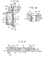
- FIG. 3A and 3B in combination with Figures 1 and 2, it is seen that the entire solenoid assembly 12 is retained assembled by a non-ferrous, flux tube 50 which has a tubular portion 51 with a closed first end 52 and an open second end 54.
- a preferable material for flux tube 50 is copper.
- Adjacent to closed end 52 is a crimp 56 which has a diameter larger than the hole 31 through closed end 33 of the housing 30. Crimp 56 serves as a stop against the closed end 33 of the housing 30 and, as is seen in Figures 1 and 2, provides an internal stop 58 for an armature to be discussed hereinafter.
- the flux tube 50 has a flange 60 which extends radially outward and has a flange face 62 that is held in abutment with the axially facing, radially extending shoulder 48 of the coupling 40.
- the radially extending flange 60 also has an outwardly facing radial surface 64 which is abutted by a fixed core element as will be discussed hereinafter.
- the flux tube 50 initially has an end portion 70 which converges toward the axis 72 of the flux tube.
- This provides an O-ring lead which allows the coupling member 40 with the sealing O-ring 46 therein to be slid over the open-end 54 of the flux tube 50 without cutting or damaging the O-ring 46 so as to clear the end of the flux tube.
- the converging end 70 of the flux tube 50 is deformed to form the flange 60 in order to hold the coupling member 40 in tight engagement with the base plate 32 of the solenoid assembly 12.
- deformation of the converging end 70 is accomplished by a process known as "Taumel Orbital Head Forming" in which a forming tool orbits around the axis 72 of the flux tube 50 so as to deform the open end 52 thereof into the radially extending annular flange 60.
- the flange 60 is formed over many high speed revolutions (for example, over 100 revolutions) of the head the forming tool with all the pressure applied to a line on the flange so that a flowing wave of material forms ahead of the orbiting tool.
- the flange 60 holds the coupling 40 in tight engagement with the shoulder 48 which results in a tight magnetic circuit.
- the flux tube 50 is in effect riveted at open end 54.
- the flux tube 50 acts three capacities, i.e., an O-ring lead for O-ring 46, a flux break, and a fastener which holds the components of the solenoid assembly 12 tightly together.
- an armature 73 which abuts the internal stop 58 formed by the crimp 56 in flux tube with a free-end 74.
- the armature 73 has a frustoconical end 75 with a frustoconical surface 76.
- Projecting from the frustoconical end 75 is a rod 78 of nonmagnetic material which pushes axially against a spool within the valve spool assembly 14, as will be further explained hereinafter.
- the rod 78 passes through a bore 80 in a fixed pole piece 82.
- Fixed core 82 has a first end 84 with a single frustoconical recess 86 that receives and compliments the frustoconical end 75 of the armature 73.
- the coil When the coil is deenergized, there in a gap 87 between the frustoconical recess 86 and the frustoconical end 75 of the armature 73.
- the flux tube 50 By employing the flux tube 50 of non-magnetizable material, short circuitry of flux around the working gap 87 is prevent and the round robin effect normally associated with stacked magnetic components is avoided, resulting in substantially all of the magnetic force being applied in the working gap.
- a second end 85 of the fixed core 82 has a peripheral flange 86 which is in abutment with the radially extending flange 62 (see also Figure 3b) of the flux tube 50.
- valve spool assembly 14 comprises a valve spool 90 having a first end 92 that is abutted by the rod 78 attached to the armature 70 and a second end 94 which abuts a coil spring 96 that is held in place by an annular insert 98.
- a bushing 99 is disposed between the first end 92 of the valve spool 90 and the valve stem 78 to prevent the valve stem from sticking to the fixed pole piece 82 of the solenoid 12.
- the valve spool 90 has a first relieved portion defining an axially extending annular space 100 and a second relieved portion defining an annular space 102 located proximate the second end 94 of the valve spool.
- a hollow core 104 which opens through the valve spool 90 via a port 106 that is in communication with the third relieved space 103, for fluid displacement behind the valve spool, as the valve spool moves away from the pole 82.
- the cylindrical spool housing 110 has four radial tank ports 120 (two of which are shown) which communicate with the internal annular space 100 around the spool 90 and four radial work ports 122 (two of which are shown), which also communicate with annular space 100.
- An axially opening work port 126 is also provided that communicates with the second annular space 102.
- Four radial pump ports 124 also communicate with the second annular space 102 around the end 94 of the valve spool 90.
- the work port 126 is in communication with the bore 104 which in turn is in communication with the third space 103 that is connected to the bore 104 by the port 106. Projecting annular lands 128 and 130 center the valve spool 90 within the valve spool housing 110 and due to their geometry provide a negative lap lag.
- the pump ports 124 When the coil 20 of the solenoid assembly 12 is deenergized, the pump ports 124 connect with the work ports 126, while the work ports 122 connect to the tank ports 120. When the coil 20 of the solenoid assembly 12 is energized, the pump ports 124 disconnect from the work ports 126 and connect to work ports 122, while the tank ports 120 are blocked from all other ports.
- valve spool assembly 16 has essentially the same elements as the two position four-way spool with the exception that in the embodiment of Figure 2, only the pressure ports 124' are present with the axial end port 126' being the tank port. Since there are no tank ports 120 and no radial work ports 122, there are no overlap problems.
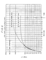
- the linearizing magnetic washer 34 cooperates with the one piece, riveted flux tube 50 to create a more linear magnet force verses displacement curve which parallels the force exerted by the low-rate spring 96.
- spring force 150, hysterisus of friction 152 and magnetic force 154 are plotted as a function of travel for an SAE-6 valve configured in accordance with the present invention. As is readily apparent, the spring force 150, hysterisus due to friction force 152, and magnetic force 154 are substantially parallel.
- the solenoid valve assembly 10 configured in accordance with the arrangement described herein, saturates earlier in the gap 87 and is a hedge against the temperature effect which lowers force as temperature increases.
- the difficulty encountered in designing an SAE-6 solenoid valve assembly is that the armature is about 8mm (0.312") in diameter and thus is too small to readily accommodate the lines of magnetic flux which are spaced a distance apart.
- the force exerted by the solenoid valve shown in Figure 5 is achievable with a coil having 1550 amp turns at 18 watts power, even with an 8mm (0.312") armature.
Landscapes
- Physics & Mathematics (AREA)
- Electromagnetism (AREA)
- Engineering & Computer Science (AREA)
- Power Engineering (AREA)
- Magnetically Actuated Valves (AREA)
Claims (7)
- Ensemble d'électrovanne (12) comportant une bobine (20) définissant un noyau creux (26) et présentant une première extrémité et une deuxième extrémité ; un boítier (30) entourant la bobine (20) où le boítier (30) présente une paroi s'étendant axialement positionnée autour de la bobine, une première paroi d'extrémité annulaire (33) sur la première extrémité de la bobine (20) et une deuxième paroi d'extrémité annulaire (32) sur la deuxième extrémité de la bobine (20) ; un tube de flux (50) en matériau non magnétique s'étendant à travers la bobine (20) et présentant une première et une deuxième extrémité (52 et 54) s'étendant respectivement à travers les première et deuxième parois d'extrémité annulaires (33, 32} du boítier (30) ; un accouplement (40) disposé contre la deuxième paroi d'extrémité annulaire (32) du boítier (30) et y recevant la deuxième extrémité (54) du tube de flux (50), l'accouplement (40) comprenant une première surface radiale (40a) aboutant à la deuxième paroi d'extrémité annulaire (32) du boítier (30) et une deuxième surface radiale (48) orientée éloignée du boítier (30) ; l'ensemble d'électrovanne (12) étant caractérisé par le fait qu'une bride radiale (60) fait saillie latéralement par rapport à la deuxième extrémité (54) du tube de flux (50), la bride radiale (60) ayant été rivetée en prise avec la deuxième surface radiale (48) de l'accouplement (40), pour maintenir l'accouplement (40) contre la deuxième paroi d'extrémité (32) du boítier (30).
- Ensemble d'électrovanne selon la revendication 1, dans lequel la bride s'étendant radialement (60) à la deuxième extrémité (54) du tube de flux (50) est réalisée en un matériau initialement de même étendue que le tube de flux (50) et est rivetée à la surface radiale (48) de l'accouplement (40) par une série d'impacts orbitaux.
- Ensemble d'électrovanne selon la revendication 2, dans lequel l'accouplement (40) présente une rainure intérieure (44) dans laquelle est posé un joint annulaire (46), et dans lequel la deuxième extrémité (54) du tube de flux (50) a été déformée par lesdits impacts orbitaux à partir d'un diamètre initial (70) inférieur au diamètre du tube de flux (50), pour permettre que l'accouplement (40) glisse aisément par-dessus la deuxième extrémité (54) du tube de flux (50) pendant l'assemblage sans que la deuxième extrémité (54) du tube de flux (50) ne morde le joint annulaire (46).
- Procédé pour fabriquer un ensemble d'électrovanne (12) comportant un bobine (20) définissant un noyau creux (26) et présentant une première extrémité et une deuxième extrémité ; un boítier (30) entourant la bobine (20) où le boítier (30) présente une paroi s'étendant axialement positionné autour de la bobine, une première paroi d'extrémité annulaire (33) sur la première extrémité de la bobine (20) et une deuxième paroi d'extrémité annulaire (32) sur la deuxième extrémité de la bobine (20) ; un tube de flux (50) en matériau non magnétique s'étendant à travers la bobine (20) et présentant une première et une deuxième extrémité (52 et 54) s'étendant respectivement à travers les première et deuxième parois d'extrémité annulaires (33, 32) du boítier (30) ; un accouplement (40) disposé contre la deuxième paroi d'extrémité annulaire (32) du boítier (30) et y recevant la deuxième extrémité (54) du tube de flux (50), l'accouplement (40) comportant une première surface radiale (40a) aboutant au boítier et une deuxième surface radiale (48) orientée opposée au boítier (30) ; le procédé étant caractérisé par le fait qu'une bride radiale (60) fait saillie latéralement par rapport à la deuxième extrémité (54) du tube de flux (50) et est formée en étant rivetée en prise avec la deuxième surface radiale (48) de l'accouplement (40), pour maintenir l'accouplement (40) contre la deuxième paroi d'extrémité (32) du boítier (30).
- Procédé selon la revendication 4, dans lequel la bride s'étendant radialement (60) à la deuxième extrémité (54) du tube de flux (50) est réalisée en un matériau initialement de même extension que le tube de flux (50) et est rivetée à la surface radiale (48) de l'accouplement (40) par une série d'impacts orbitaux.
- Procédé selon la revendication 5, dans lequel l'accouplement (40) présente une rainure intérieure (44) dans laquelle est posé un joint annulaire (46), et dans lequel, avant de déformer la deuxième extrémité (54) du tube de flux (50) par lesdits impacts d'orbitaux, la deuxième extrémité (54) présente un diamètre initial (70) inférieur au diamètre du tube de flux (50), pour permettre que l'accouplement (40) glisse aisément par-dessus de la deuxième extrémité (54) du tube de flux (50) pendant l'assemblage sans que la deuxième extrémité (54) du tube de flux (50) ne morde le joint annulaire (46).
- Ensemble d'électrovanne fabriqué par un procédé selon l'une quelconque des revendications 4 à 6.
Applications Claiming Priority (2)
| Application Number | Priority Date | Filing Date | Title |
|---|---|---|---|
| US1148 | 1997-12-30 | ||
| US09/001,148 US6092784A (en) | 1997-12-30 | 1997-12-30 | Coil assembly useful in solenoid valves |
Publications (3)
| Publication Number | Publication Date |
|---|---|
| EP0928010A2 EP0928010A2 (fr) | 1999-07-07 |
| EP0928010A3 EP0928010A3 (fr) | 2000-07-12 |
| EP0928010B1 true EP0928010B1 (fr) | 2005-06-15 |
Family
ID=21694625
Family Applications (1)
| Application Number | Title | Priority Date | Filing Date |
|---|---|---|---|
| EP98310684A Expired - Lifetime EP0928010B1 (fr) | 1997-12-30 | 1998-12-23 | Dispositif de bobine utilisé dans les électrovannes |
Country Status (3)
| Country | Link |
|---|---|
| US (1) | US6092784A (fr) |
| EP (1) | EP0928010B1 (fr) |
| DE (1) | DE69830562T2 (fr) |
Families Citing this family (21)
| Publication number | Priority date | Publication date | Assignee | Title |
|---|---|---|---|---|
| US6392516B1 (en) * | 1998-12-04 | 2002-05-21 | Tlx Technologies | Latching solenoid with improved pull force |
| US7914442B1 (en) | 1999-03-01 | 2011-03-29 | Gazdzinski Robert F | Endoscopic smart probe and method |
| US8636648B2 (en) | 1999-03-01 | 2014-01-28 | West View Research, Llc | Endoscopic smart probe |
| US10973397B2 (en) | 1999-03-01 | 2021-04-13 | West View Research, Llc | Computerized information collection and processing apparatus |
| US8068897B1 (en) | 1999-03-01 | 2011-11-29 | Gazdzinski Robert F | Endoscopic smart probe and method |
| US6918409B1 (en) * | 2001-12-13 | 2005-07-19 | Honeywell International Inc. | Spool and poppet inlet metering valve |
| EP1511954B1 (fr) * | 2002-06-12 | 2006-01-11 | FSP Fluid Systems Partners Holding AG | Soupape a visser |
| EP1561225B1 (fr) * | 2002-11-14 | 2007-01-03 | WOCO Industrietechnik GmbH | Systeme a induit plongeur avec flux de courant magnetique reglable |
| US8297532B2 (en) * | 2008-06-09 | 2012-10-30 | Caterpillar Inc. | Apparatus for cooling a fuel injector |
| US8585014B2 (en) * | 2009-05-13 | 2013-11-19 | Keihin Corporation | Linear solenoid and valve device using the same |
| JP2011077355A (ja) * | 2009-09-30 | 2011-04-14 | Keihin Corp | リニアソレノイド及びそれを用いたバルブ装置 |
| US8733732B2 (en) * | 2010-05-24 | 2014-05-27 | Eaton Corporation | Pressurized o-ring pole piece seal for a manifold |
| KR101158423B1 (ko) * | 2010-05-26 | 2012-06-22 | 주식회사 케피코 | 차량의 자동변속기용 유압 솔레노이드 밸브 |
| US8733729B2 (en) | 2011-10-10 | 2014-05-27 | Liebert Corporation | Back pressure capable solenoid operated diaphragm pilot valve |
| US9097362B2 (en) * | 2012-02-27 | 2015-08-04 | Parker-Hannifin Corporation | Fast switching hydraulic pilot valve with hydraulic feedback |
| CN104854281B (zh) | 2012-12-14 | 2017-06-09 | 伊顿公司 | 用于负载的受控降低和提升的系统和方法 |
| CN107407435A (zh) * | 2015-02-12 | 2017-11-28 | 伊顿公司 | 具有放大行程的螺线管 |
| JP6421745B2 (ja) * | 2015-12-11 | 2018-11-14 | オムロン株式会社 | リレー |
| JP6575343B2 (ja) | 2015-12-11 | 2019-09-18 | オムロン株式会社 | リレー |
| US10726985B2 (en) * | 2018-03-22 | 2020-07-28 | Schaeffler Technologies AG & Co. KG | Multi-stage actuator assembly |
| CN219493226U (zh) * | 2023-03-23 | 2023-08-08 | 比亚迪股份有限公司 | 集成阀和车辆 |
Family Cites Families (17)
| Publication number | Priority date | Publication date | Assignee | Title |
|---|---|---|---|---|
| US3262027A (en) * | 1964-04-06 | 1966-07-19 | Automatic Switch Co | Solenoid structure and mounting means therefor |
| US3593241A (en) * | 1969-07-18 | 1971-07-13 | Alfred J Ludwig | Solenoid valve having a slotted flux sleeve for nesting the winding leads |
| US4442998A (en) * | 1979-07-24 | 1984-04-17 | Aisin Seiki Kabushiki Kaisha | Electromagnetic valve unit |
| JPS6127137Y2 (fr) * | 1981-01-08 | 1986-08-13 | ||
| US4805870A (en) * | 1983-02-03 | 1989-02-21 | Emerson Electric Co. | Coil retainer for solenoid |
| DE3479436D1 (en) * | 1983-08-25 | 1989-09-21 | Ckd Corp | Miniature solenoid valve |
| US4638974A (en) * | 1984-01-06 | 1987-01-27 | Zeuner Kenneth W | Electrohydraulic valve assemblies and method |
| JPS61103076A (ja) * | 1984-10-25 | 1986-05-21 | Toyoda Mach Works Ltd | リニアソレノイドバルブ |
| US4649360A (en) * | 1986-02-28 | 1987-03-10 | Parker Vannifin Corporation | Solenoid valve with contractible assembly ring |
| US4697608A (en) * | 1986-04-30 | 1987-10-06 | Eaton Corporation | Electromagnetic valve assembly |
| KR930001020B1 (ko) * | 1987-06-16 | 1993-02-12 | 스미도모 덴기 고오교오 가부시기가이샤 | 액압 제어장치 및 이것을 사용한 브레이크장치 |
| US4880205A (en) * | 1987-06-30 | 1989-11-14 | Parker Hannifin Corporation | Hung diaphragm solenoid valve |
| IT1211628B (it) * | 1987-12-24 | 1989-11-03 | Weber Srl | Valvola a comando elettromagnetico per il controllo di una portata d aria in un dispositivo di alimentazione del carburante per motore acombustione interna |
| JPH02180390A (ja) * | 1988-12-30 | 1990-07-13 | Aisin Aw Co Ltd | 圧力調整弁 |
| US5002253A (en) * | 1989-10-30 | 1991-03-26 | Sterling Hydraulics, Inc. | Solenoid valve |
| JP2898081B2 (ja) * | 1990-11-05 | 1999-05-31 | アイシン・エィ・ダブリュ株式会社 | リニヤソレノイドバルブ並びにその組立方法 |
| CA2147156C (fr) * | 1992-10-15 | 1999-12-21 | Chester D. Campbell | Detente pour systeme de conditionnement d'air a solenoide proportionnel |
-
1997
- 1997-12-30 US US09/001,148 patent/US6092784A/en not_active Expired - Lifetime
-
1998
- 1998-12-23 EP EP98310684A patent/EP0928010B1/fr not_active Expired - Lifetime
- 1998-12-23 DE DE69830562T patent/DE69830562T2/de not_active Expired - Lifetime
Also Published As
| Publication number | Publication date |
|---|---|
| DE69830562D1 (de) | 2005-07-21 |
| EP0928010A2 (fr) | 1999-07-07 |
| DE69830562T2 (de) | 2006-05-11 |
| US6092784A (en) | 2000-07-25 |
| EP0928010A3 (fr) | 2000-07-12 |
Similar Documents
| Publication | Publication Date | Title |
|---|---|---|
| EP0928010B1 (fr) | Dispositif de bobine utilisé dans les électrovannes | |
| JP4285354B2 (ja) | リニアソレノイドおよび電磁弁 | |
| US7159615B2 (en) | Flow control valve | |
| US6619616B1 (en) | Solenoid valve device | |
| US6542059B2 (en) | Solenoid for electromagnetic valve | |
| US20210278007A1 (en) | Solenoid | |
| US4638973A (en) | Inline solenoid operated slide valve | |
| US20210278008A1 (en) | Solenoid | |
| JP2002188749A (ja) | 電磁弁 | |
| US4763091A (en) | Air gap setting device for electromagnets | |
| US6701959B1 (en) | High flow rate balanced poppet valve | |
| US20080230452A1 (en) | Spool valve | |
| US7992839B2 (en) | Electrohydraulic valve having a solenoid actuator plunger with an armature and a bushing | |
| JPH11264403A (ja) | 統合電気油圧アクチュエーター | |
| JP4214964B2 (ja) | 電磁弁 | |
| US20020195151A1 (en) | Pulse-width modulated solenoid valve including axial stop spool valve | |
| US4612845A (en) | Electromagnetically operated dual-valve flow-control assembly | |
| EP1617116B1 (fr) | Electrovanne | |
| US4694270A (en) | Electromagnetic proportional actuator | |
| EP1284384A2 (fr) | Solénoide pour une soupape électromagnétique | |
| JP2004316855A (ja) | 比例電磁弁 | |
| EP1255067A1 (fr) | Soupape de régulation de la pression électromagnétique | |
| JP4301318B2 (ja) | ブリード式バルブ装置 | |
| US6091314A (en) | Piezoelectric booster for an electromagnetic actuator | |
| US11783979B2 (en) | Solenoid |
Legal Events
| Date | Code | Title | Description |
|---|---|---|---|
| PUAI | Public reference made under article 153(3) epc to a published international application that has entered the european phase |
Free format text: ORIGINAL CODE: 0009012 |
|
| AK | Designated contracting states |
Kind code of ref document: A2 Designated state(s): BE DE IT SE |
|
| AX | Request for extension of the european patent |
Free format text: AL;LT;LV;MK;RO;SI |
|
| PUAL | Search report despatched |
Free format text: ORIGINAL CODE: 0009013 |
|
| AK | Designated contracting states |
Kind code of ref document: A3 Designated state(s): AT BE CH CY DE DK ES FI FR GB GR IE IT LI LU MC NL PT SE |
|
| AX | Request for extension of the european patent |
Free format text: AL;LT;LV;MK;RO;SI |
|
| RIC1 | Information provided on ipc code assigned before grant |
Free format text: 7H 01F 7/06 A, 7H 01F 7/16 B, 7F 16K 31/06 B |
|
| RAP1 | Party data changed (applicant data changed or rights of an application transferred) |
Owner name: PARKER HANNIFIN CORPORATION |
|
| 17P | Request for examination filed |
Effective date: 20010108 |
|
| AKX | Designation fees paid |
Free format text: BE DE IT SE |
|
| 17Q | First examination report despatched |
Effective date: 20040112 |
|
| GRAP | Despatch of communication of intention to grant a patent |
Free format text: ORIGINAL CODE: EPIDOSNIGR1 |
|
| GRAS | Grant fee paid |
Free format text: ORIGINAL CODE: EPIDOSNIGR3 |
|
| GRAA | (expected) grant |
Free format text: ORIGINAL CODE: 0009210 |
|
| AK | Designated contracting states |
Kind code of ref document: B1 Designated state(s): BE DE IT SE |
|
| REF | Corresponds to: |
Ref document number: 69830562 Country of ref document: DE Date of ref document: 20050721 Kind code of ref document: P |
|
| REG | Reference to a national code |
Ref country code: SE Ref legal event code: TRGR |
|
| PLBE | No opposition filed within time limit |
Free format text: ORIGINAL CODE: 0009261 |
|
| STAA | Information on the status of an ep patent application or granted ep patent |
Free format text: STATUS: NO OPPOSITION FILED WITHIN TIME LIMIT |
|
| 26N | No opposition filed |
Effective date: 20060316 |
|
| PGFP | Annual fee paid to national office [announced via postgrant information from national office to epo] |
Ref country code: BE Payment date: 20090126 Year of fee payment: 11 |
|
| BERE | Be: lapsed |
Owner name: *PARKER HANNIFIN CORP. Effective date: 20091231 |
|
| PG25 | Lapsed in a contracting state [announced via postgrant information from national office to epo] |
Ref country code: BE Free format text: LAPSE BECAUSE OF NON-PAYMENT OF DUE FEES Effective date: 20091231 |
|
| PGFP | Annual fee paid to national office [announced via postgrant information from national office to epo] |
Ref country code: IT Payment date: 20141227 Year of fee payment: 17 Ref country code: DE Payment date: 20141230 Year of fee payment: 17 |
|
| PGFP | Annual fee paid to national office [announced via postgrant information from national office to epo] |
Ref country code: SE Payment date: 20150102 Year of fee payment: 17 |
|
| REG | Reference to a national code |
Ref country code: DE Ref legal event code: R119 Ref document number: 69830562 Country of ref document: DE |
|
| REG | Reference to a national code |
Ref country code: SE Ref legal event code: EUG |
|
| PG25 | Lapsed in a contracting state [announced via postgrant information from national office to epo] |
Ref country code: SE Free format text: LAPSE BECAUSE OF NON-PAYMENT OF DUE FEES Effective date: 20151224 |
|
| REG | Reference to a national code |
Ref country code: DE Ref legal event code: R082 Ref document number: 69830562 Country of ref document: DE Representative=s name: HASELTINE LAKE KEMPNER LLP, DE Ref country code: DE Ref legal event code: R082 Ref document number: 69830562 Country of ref document: DE Representative=s name: HASELTINE LAKE LLP, DE |
|
| PG25 | Lapsed in a contracting state [announced via postgrant information from national office to epo] |
Ref country code: DE Free format text: LAPSE BECAUSE OF NON-PAYMENT OF DUE FEES Effective date: 20160701 |
|
| PG25 | Lapsed in a contracting state [announced via postgrant information from national office to epo] |
Ref country code: IT Free format text: LAPSE BECAUSE OF NON-PAYMENT OF DUE FEES Effective date: 20151223 |