EP0928043B1 - Verbindungsvorrichtung mittels Käfigklemme - Google Patents
Verbindungsvorrichtung mittels Käfigklemme Download PDFInfo
- Publication number
- EP0928043B1 EP0928043B1 EP98403308A EP98403308A EP0928043B1 EP 0928043 B1 EP0928043 B1 EP 0928043B1 EP 98403308 A EP98403308 A EP 98403308A EP 98403308 A EP98403308 A EP 98403308A EP 0928043 B1 EP0928043 B1 EP 0928043B1
- Authority
- EP
- European Patent Office
- Prior art keywords
- arm
- loop
- cage
- branch
- connection
- Prior art date
- Legal status (The legal status is an assumption and is not a legal conclusion. Google has not performed a legal analysis and makes no representation as to the accuracy of the status listed.)
- Expired - Lifetime
Links
- 239000004020 conductor Substances 0.000 claims description 3
- 239000002184 metal Substances 0.000 claims 1
- 238000000605 extraction Methods 0.000 description 3
- 238000013459 approach Methods 0.000 description 2
- 238000003032 molecular docking Methods 0.000 description 2
- 238000006243 chemical reaction Methods 0.000 description 1
- 238000006073 displacement reaction Methods 0.000 description 1
- 239000011810 insulating material Substances 0.000 description 1
- 238000012423 maintenance Methods 0.000 description 1
- 230000000717 retained effect Effects 0.000 description 1
Images

Classifications
-
- H—ELECTRICITY
- H01—ELECTRIC ELEMENTS
- H01R—ELECTRICALLY-CONDUCTIVE CONNECTIONS; STRUCTURAL ASSOCIATIONS OF A PLURALITY OF MUTUALLY-INSULATED ELECTRICAL CONNECTING ELEMENTS; COUPLING DEVICES; CURRENT COLLECTORS
- H01R4/00—Electrically-conductive connections between two or more conductive members in direct contact, i.e. touching one another; Means for effecting or maintaining such contact; Electrically-conductive connections having two or more spaced connecting locations for conductors and using contact members penetrating insulation
- H01R4/28—Clamped connections, spring connections
- H01R4/48—Clamped connections, spring connections utilising a spring, clip, or other resilient member
- H01R4/4809—Clamped connections, spring connections utilising a spring, clip, or other resilient member using a leaf spring to bias the conductor toward the busbar
- H01R4/4811—Spring details
- H01R4/4816—Spring details the spring shape preventing insertion of the conductor end when the spring is unbiased
-
- H—ELECTRICITY
- H01—ELECTRIC ELEMENTS
- H01R—ELECTRICALLY-CONDUCTIVE CONNECTIONS; STRUCTURAL ASSOCIATIONS OF A PLURALITY OF MUTUALLY-INSULATED ELECTRICAL CONNECTING ELEMENTS; COUPLING DEVICES; CURRENT COLLECTORS
- H01R4/00—Electrically-conductive connections between two or more conductive members in direct contact, i.e. touching one another; Means for effecting or maintaining such contact; Electrically-conductive connections having two or more spaced connecting locations for conductors and using contact members penetrating insulation
- H01R4/28—Clamped connections, spring connections
- H01R4/48—Clamped connections, spring connections utilising a spring, clip, or other resilient member
- H01R4/4809—Clamped connections, spring connections utilising a spring, clip, or other resilient member using a leaf spring to bias the conductor toward the busbar
- H01R4/484—Spring housing details
- H01R4/4842—Spring housing details the spring housing being provided with a single opening for insertion of a spring-activating tool
-
- H—ELECTRICITY
- H01—ELECTRIC ELEMENTS
- H01R—ELECTRICALLY-CONDUCTIVE CONNECTIONS; STRUCTURAL ASSOCIATIONS OF A PLURALITY OF MUTUALLY-INSULATED ELECTRICAL CONNECTING ELEMENTS; COUPLING DEVICES; CURRENT COLLECTORS
- H01R13/00—Details of coupling devices of the kinds covered by groups H01R12/70 or H01R24/00 - H01R33/00
- H01R13/02—Contact members
- H01R13/193—Means for increasing contact pressure at the end of engagement of coupling part, e.g. zero insertion force or no friction
-
- H—ELECTRICITY
- H01—ELECTRIC ELEMENTS
- H01R—ELECTRICALLY-CONDUCTIVE CONNECTIONS; STRUCTURAL ASSOCIATIONS OF A PLURALITY OF MUTUALLY-INSULATED ELECTRICAL CONNECTING ELEMENTS; COUPLING DEVICES; CURRENT COLLECTORS
- H01R13/00—Details of coupling devices of the kinds covered by groups H01R12/70 or H01R24/00 - H01R33/00
- H01R13/02—Contact members
- H01R13/20—Pins, blades, or sockets shaped, or provided with separate member, to retain co-operating parts together
Definitions
- the present invention relates to a connection device which comprises at least one terminal of the type having an elastic cage and a conductive part that current, the latter providing the support function for the cage.
- connection devices of this type are well known, for example from DE 3911459. They are associated with an apparatus or electrical member and allow to tighten in the terminal a cable to connect to the device or the body without having to resort to a clamping screw.
- the elastic cage is placed near one end of the support piece close to an access face of the apparatus and comprises a support wing applied to the support piece, a clamping wing equipped with a wedging clamping conductor window and a loop connecting the support wing to the clamping wing and forming a spring to secure the driver.
- the object of the invention is therefore to take advantage of the elastic cage terminals provided in an electrical appliance for connecting a cable, in order to make a simple and reliable connection with another appliance or with a current-conducting member.
- connection device has an insulating block which carries, on the one hand, a branch capable of ensuring the opening of the elastic cage and, on the other hand, a conductive connection branch, the two branches being directed substantially parallel to the support wing of the cage and arranged so that when the block docked the cage, the opening branch flexed the loop to allow the introduction of the connecting branch in the tightening window
- the two branches are rigid and a space remains in a tight position between the opening branch and its housing in the expansion direction of the elastic loop so that the application pressure of the connecting branch on the conductive part due to the pressure exerted by the loop on the opening branch.
- One of the branches can be provided with a shape contributing to retain the block in the connected position.
- the insulating body also has at least one interconnection element such as a conductive pin parallel to the connection branch and connected thereto for connection with another device.
- Figure 1 schematically shows a connection device according to the invention.
- FIG. 2 shows in perspective a particular embodiment of the connection block of the device.
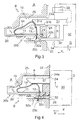
- Figures 3 and 4 illustrate the device respectively docking and the connected state.
- the electrical apparatus A whose outline is shown in dashed lines is a low-voltage electrical appliance with a control distribution or protection function.
- the apparatus A comprises a plurality of elastic-type connection terminals B capable of receiving and connecting the ends of the conductors C.
- the device according to the invention comprises the terminals B as well as a multipole-D-connection block. heard to be unipolar too.
- Each terminal B comprises an elastic cage 10 and an elongated flat piece 20 which conducts the current and the support function of the cage.
- the elastic cage 10 is placed on the front 20a of the part 20 of the support near an end 21 thereof close to an access wall 22 of the apparatus and comprises a support wing 11 applied to the support piece along the length thereof, a clamping wing 12 provided with a wedging clamping window 13 and a spring loop 14 connecting the support wing 11 to the 12.
- the back 20b of the part 20 is used to make contact with the cable C and has a bump 20c for this purpose.
- the apparatus comprises conventionally in its access wall 22 and for each terminal B an opening 23 of intreduction for the cable C to connect to the piece 20 and an opening 24 for engaging a tool: as is known, this tool must be able to press the loop to loosen the terminal by allowing the window 13 to be removed to introduce the cable therein.
- this tool must be able to press the loop to loosen the terminal by allowing the window 13 to be removed to introduce the cable therein.
- the support piece 20, the support wing 11 of the elastic cage 10, the openings 23.24 of the terminal are oriented in the same direction X which is the introduction of the cable C.
- the Y direction of relaxation of the loop 14 and displacement of the wing 12 is substantially perpendicular to X.
- the opening 24 gives access to a housing 25 adjacent to that of the cage 10 so that the tool can debate in this housing to press the loop 14 away from the direction Y by bearing on the outer edge 24a of the opening 24.
- Block D has an insulating body 30 which carries on the one hand an opening branch 31 of the cage and on the other hand a connecting conductive branch 32.
- the two branches 31, 32 are directed substantially parallel to the support wing 11 of the cage 10 along X and arranged so that when the body 30 accosts the apparatus A, the opening branch 31 flexes the loop 14 (see dashed in Figure 3) to allow the introduction of the connection branch 32 in the window 13.
- the two branches offer a predetermined distance between them h and are rigid so that the contact pressure of the branch connection 32 on the conductive part 20 is due to the pressure exerted by the loop 14 on the opening branch 31.
- it remains in the clamping position of the branch 32 of the block against the back 20b of the part 20 of the terminal a space e between the branch 31 and the adjacent surfaces of the opening 24, in particular at its outer edge 24a, and the housing 25.
- the two branches 31, 32 are metallic and interconnected rigidly; the branch 31 may also be of insulating material and optionally come from a part with the body 30.
- the connecting branch 32 provides the desired connection of current between the part 20 and another member or apparatus; it can be connected in the body 30 to another plug or pin 33 (see Figure 2) which establishes the connection with another adjacent device or with a power device.
- the branch 31 has a slope 31a to gradually dock the loop 14 and optionally an anti-extraction conformation, for example and as shown in Figure 3 a recessed form 31b which cooperates with the loop or a hard point provided in a face of the housing 25 to contribute to the maintenance of the block D in connected and assembled position on the apparatus A.
- the branch 32 has a slope 32a for sliding on the boss 20c provided at the end 21 of the piece 20 and it is likely to be applied against the boss by its edge 32b located on the side of the branch 31.
- the branch 32 may provide an anti-extraction form 32c as shown in Figure 4.
- the branches 31,32 have any suitable shape, the branch 31 being for example a flat plug and branch 32 a round brooch.
- the user approaches the insulating block D of the apparatus in the X direction.
- the pin 33 into a terminal or a connection member (not shown) of another apparatus or conductive member, he causes the opening branch 31 of the block D to enter the opening 24 of the terminal B of the apparatus A; the slope 31a of the branch 31 is applied to the front rounding of the loop 14, so that the buckle flexes: the connecting branch 12 of the cage 10 comes in the position shown in dashed lines in Figure 3 to make the window 13 accessible.
- the block is retained against an extraction in the direction X 'by cooperation withdrawal 31b of the branch 31 with the loop 14 or with a hard point provided on one side of the housing 25 or by cooperation of the withdrawal 32c of the branch 32 with the hump 2Cc of the conductive part 20. It can also be provided in the usual manner a hooking means or snap the block on the device.
Landscapes
- Connections Arranged To Contact A Plurality Of Conductors (AREA)
Claims (6)
- Verbindungsvorrichtung, die aufweist:- mindestens eine Klemme (B) von dem Typ, der einen elastischen Käfig (10) und ein leitendes Trägerbauteil (20) aufweist, wobei der elastische Käfig in der Nähe eines Endes des Trägerbauteils angeordnet ist und aus einem Auflageflügel (11), der auf das Trägerbauteil aufgelegt ist, einem Klemmflügel (12), der mit einem Schlitz (13) zum Festklemmen eines Leiters durch Klemmwirkung versehen ist, und einer Schleife (14) besteht, die eine Feder bildet und den Auflageflügel mit dem Klemmflügel verbindet,
gekennzeichnet durch- einen Isolierblock (D), der einerseits einen Öffnungszweig (31) des elastischen Käfigs (10) und andererseits einen leitenden Verbindungszweig (32) trägt,- wobei die beiden Zweige (31, 32) im Wesentlichen parallel zum Auflageflügel (11) des Käfigs ausgerichtet und so angeordnet sind, dass, wenn der Block gegen den Käfig anlegt, der Öffnungszweig (31) die Schleife krümmt, um die Einführung des Verbindungszweigs (32) in den Klemmschlitz zu erlauben. - Vorrichtung nach Anspruch 1, dadurch gekennzeichnet, dass die beiden Zweige (31, 32) starr sind und dass in der festgeklemmten Stellung zwischen dem Öffnungszweig (31) und seinem Sitz (25) ein Zwischenraum (e) bleibt, damit der Kontaktdruck des Verbindungszweigs (32) auf das leitende Bauteil (20) durch den Druck verursacht wird, der von der Schleife (14) auf den Öffnungszweig (31) ausgeübt wird.
- Vorrichtung nach Anspruch 2, dadurch gekennzeichnet, dass die beiden Zweige (31, 32) metallisch und starr miteinander verbunden sind.
- Vorrichtung nach Anspruch 1, dadurch gekennzeichnet, dass der Zweig (31) eine Gestaltung (31b) aufweist, die mit der Schleife (14) zusammenwirkt, um zum Halt der Verbindung des Blocks (D) beizutragen.
- Vorrichtung nach Anspruch 1, dadurch gekennzeichnet, dass der Zweig (32) eine Gestaltung (32c) aufweist, die mit einer Wölbung (20c) des leitenden Bauteils (20) zusammenwirkt, um zum Halt der Verbindung des Blocks (D) beizutragen.
- Vorrichtung nach Anspruch 1, dadurch gekennzeichnet, dass der Isolierblock (D) mindestens einen stromführenden Verbindungsstift (33) aufweist, der parallel zum Verbindungszweig (32) liegt und im Körper (30) mit dem Verbindungszweig verbunden ist.
Applications Claiming Priority (2)
| Application Number | Priority Date | Filing Date | Title |
|---|---|---|---|
| FR9716846A FR2773274B1 (fr) | 1997-12-29 | 1997-12-29 | Dispositif de connexion a cage elastique |
| FR9716846 | 1997-12-29 |
Publications (2)
| Publication Number | Publication Date |
|---|---|
| EP0928043A1 EP0928043A1 (de) | 1999-07-07 |
| EP0928043B1 true EP0928043B1 (de) | 2006-04-12 |
Family
ID=9515417
Family Applications (1)
| Application Number | Title | Priority Date | Filing Date |
|---|---|---|---|
| EP98403308A Expired - Lifetime EP0928043B1 (de) | 1997-12-29 | 1998-12-24 | Verbindungsvorrichtung mittels Käfigklemme |
Country Status (5)
| Country | Link |
|---|---|
| US (1) | US6168479B1 (de) |
| EP (1) | EP0928043B1 (de) |
| JP (1) | JPH11260434A (de) |
| DE (1) | DE69834169D1 (de) |
| FR (1) | FR2773274B1 (de) |
Cited By (5)
| Publication number | Priority date | Publication date | Assignee | Title |
|---|---|---|---|---|
| EP3116067A1 (de) | 2015-07-10 | 2017-01-11 | ABB Schweiz AG | Verbindungsvorrichtung mit steckklemme |
| DE102016110174A1 (de) | 2015-07-10 | 2017-01-12 | Abb Schweiz Ag | Verbindungsvorrichtung mit Steckklemme |
| DE102016110189A1 (de) | 2015-07-10 | 2017-01-12 | Abb Schweiz Ag | Verbindungsvorrichtung mit Steckklemme |
| DE102016110176A1 (de) | 2015-07-10 | 2017-01-12 | Abb Schweiz Ag | Verbindungsvorrichtung mit Steckklemme |
| EP3118933A1 (de) | 2015-07-10 | 2017-01-18 | ABB Schweiz AG | Verbindungsvorrichtung mit steckklemme |
Families Citing this family (6)
| Publication number | Priority date | Publication date | Assignee | Title |
|---|---|---|---|---|
| FR2809872B1 (fr) * | 2000-05-30 | 2002-08-09 | Sylea | Dispositif de liaison electrique pour organe de contact electrique male et element de boitier destine a recevoir un tel dispositif |
| EP1715546A1 (de) * | 2005-04-20 | 2006-10-25 | Rockwell Automation AG | Steckbare elektrische Verbindung |
| EP1837887A1 (de) * | 2006-03-20 | 2007-09-26 | Siemens Aktiengesellschaft | Eine Verbindungsvorrichtung und diese enthaltendes Niederspannungs-Schaltgerät |
| DE102006041841A1 (de) * | 2006-09-06 | 2008-03-27 | Edin Begimamovic | Vorrichtung und Verfahren zum Einführen eines Leiterdrahts in eine Federkraftklemme |
| DE202006015363U1 (de) * | 2006-10-05 | 2008-02-21 | Wieland Electric Gmbh | Federkraftklemmstelle |
| FR2954604B1 (fr) * | 2009-12-22 | 2015-02-20 | Legrand France | Borne de connexion electrique automatique et appareillage electrique comportant une telle borne |
Family Cites Families (3)
| Publication number | Priority date | Publication date | Assignee | Title |
|---|---|---|---|---|
| DE3911459A1 (de) * | 1989-04-05 | 1990-10-11 | Wago Verwaltungs Gmbh | Schraubenlose anschluss- und/oder verbindungsklemme |
| DE9414939U1 (de) * | 1994-09-14 | 1995-02-09 | Siemens AG, 80333 München | Reihenklemme mit schraubenlosen Anschlußklemmen |
| DE4435781A1 (de) * | 1994-10-06 | 1996-04-11 | Siemens Ag | Federkraftklemme |
-
1997
- 1997-12-29 FR FR9716846A patent/FR2773274B1/fr not_active Expired - Fee Related
-
1998
- 1998-12-24 EP EP98403308A patent/EP0928043B1/de not_active Expired - Lifetime
- 1998-12-24 DE DE69834169T patent/DE69834169D1/de not_active Expired - Lifetime
- 1998-12-28 US US09/221,117 patent/US6168479B1/en not_active Expired - Fee Related
-
1999
- 1999-01-04 JP JP11000213A patent/JPH11260434A/ja not_active Withdrawn
Cited By (6)
| Publication number | Priority date | Publication date | Assignee | Title |
|---|---|---|---|---|
| EP3116067A1 (de) | 2015-07-10 | 2017-01-11 | ABB Schweiz AG | Verbindungsvorrichtung mit steckklemme |
| DE102016110174A1 (de) | 2015-07-10 | 2017-01-12 | Abb Schweiz Ag | Verbindungsvorrichtung mit Steckklemme |
| DE102016110189A1 (de) | 2015-07-10 | 2017-01-12 | Abb Schweiz Ag | Verbindungsvorrichtung mit Steckklemme |
| DE102016110176A1 (de) | 2015-07-10 | 2017-01-12 | Abb Schweiz Ag | Verbindungsvorrichtung mit Steckklemme |
| EP3118933A1 (de) | 2015-07-10 | 2017-01-18 | ABB Schweiz AG | Verbindungsvorrichtung mit steckklemme |
| DE102016110189B4 (de) | 2015-07-10 | 2022-09-15 | Abb Schweiz Ag | Verbindungsvorrichtung mit Steckklemme |
Also Published As
| Publication number | Publication date |
|---|---|
| US6168479B1 (en) | 2001-01-02 |
| FR2773274B1 (fr) | 2000-02-11 |
| FR2773274A1 (fr) | 1999-07-02 |
| DE69834169D1 (de) | 2006-05-24 |
| EP0928043A1 (de) | 1999-07-07 |
| JPH11260434A (ja) | 1999-09-24 |
Similar Documents
| Publication | Publication Date | Title |
|---|---|---|
| EP0928043B1 (de) | Verbindungsvorrichtung mittels Käfigklemme | |
| US7140887B2 (en) | Electrical wiring device with multiple types of wire terminations | |
| EP1916743A1 (de) | Elektrisches Gerät, das mindestens eine Federanschlussklemme umfasst | |
| CA1208731A (fr) | Dispositif de connexion pour conducteur electrique | |
| EP0772256B1 (de) | Elektrisches Gerät mit Anschlussklemmen, die durch eine Blende mit Flügeln geschützt sind | |
| EP1411590B1 (de) | Elastische Anschlussklemme | |
| EP3487006B1 (de) | Elektrisches system, das ein elektrogerät und ein auswechselbares verbindungsmodul umfasst | |
| EP0102285B1 (de) | Elektrischer Druckkontakt mit eingebautem Schliess- und Unterbrechungsvermögen | |
| EP1026782B1 (de) | Verbindungsblock für elektrische Geräte | |
| EP1058348B1 (de) | Elektrische Versorgungseinrichtung für elektrische Leistungsapparatemodule wie Schutzschalter, sowie ein die Vorrichtung enthaltendes Schaltgerät | |
| FR2707429A1 (fr) | Accessoire de raccordement. | |
| FR2577075A1 (fr) | Borne de connexion mixte pour circuit imprime et appareil electronique equipe d'une telle borne | |
| EP1156551A1 (de) | Elektrisches Gerät mit elastischen Käfigklemmen | |
| EP1610416B1 (de) | Elektrisches Gerät angepast um mit einer kammförmigen Sammelschiene zusammenzuwirken | |
| OA11387A (fr) | Dispositif de raccordement électrique d'une plage de contact d'un appareil électrique tel un disjoncteur à un dispositif de traitement d'informations tel une carte électronique. | |
| WO2006048530A1 (fr) | Element de bornier et connecteur sans vis | |
| EP0896386A1 (de) | Elektrisches Gerät mit Isolationsverdrägungsklemmen | |
| EP1160944A1 (de) | Modulares elektrisches Gerät mit Schnappverbindung an isoliertem Verteiler | |
| FR2877138A1 (fr) | Sectionneur a fusibles | |
| CH389723A (fr) | Dispositif de connexion électrique comprenant une plaque à bornes et une prise de mesure | |
| EP3651273A1 (de) | Elektrische anschlussvorrichtung der vor ein elektrisches schutzgerät geschalteten klemmen | |
| FR2900508A1 (fr) | Barre omnibus pour repartition electrique | |
| EP2518833B1 (de) | Verbindungsklemme mit Feder | |
| FR2999348A1 (fr) | Dispositif d'alimentation electrique d'au moins un appareil | |
| FR3101192A1 (fr) | Appareil de coupure électrique à fusible |
Legal Events
| Date | Code | Title | Description |
|---|---|---|---|
| PUAI | Public reference made under article 153(3) epc to a published international application that has entered the european phase |
Free format text: ORIGINAL CODE: 0009012 |
|
| AK | Designated contracting states |
Kind code of ref document: A1 Designated state(s): DE ES GB IT |
|
| AX | Request for extension of the european patent |
Free format text: AL;LT;LV;MK;RO;SI |
|
| RAP1 | Party data changed (applicant data changed or rights of an application transferred) |
Owner name: SCHNEIDER ELECTRIC INDUSTRIES SA |
|
| 17P | Request for examination filed |
Effective date: 19990726 |
|
| AKX | Designation fees paid |
Free format text: DE ES GB IT |
|
| RAP1 | Party data changed (applicant data changed or rights of an application transferred) |
Owner name: SCHNEIDER ELECTRIC INDUSTRIES SA |
|
| RAP1 | Party data changed (applicant data changed or rights of an application transferred) |
Owner name: SCHNEIDER ELECTRONIC INDUSTRIES SAS |
|
| RAP1 | Party data changed (applicant data changed or rights of an application transferred) |
Owner name: SCHNEIDER ELECTRIC INDUSTRIES SAS |
|
| GRAP | Despatch of communication of intention to grant a patent |
Free format text: ORIGINAL CODE: EPIDOSNIGR1 |
|
| GRAS | Grant fee paid |
Free format text: ORIGINAL CODE: EPIDOSNIGR3 |
|
| GRAA | (expected) grant |
Free format text: ORIGINAL CODE: 0009210 |
|
| AK | Designated contracting states |
Kind code of ref document: B1 Designated state(s): DE ES GB IT |
|
| PG25 | Lapsed in a contracting state [announced via postgrant information from national office to epo] |
Ref country code: IT Free format text: LAPSE BECAUSE OF FAILURE TO SUBMIT A TRANSLATION OF THE DESCRIPTION OR TO PAY THE FEE WITHIN THE PRE;WARNING: LAPSES OF ITALIAN PATENTS WITH EFFECTIVE DATE BEFORE 2007 MAY HAVE OCCURRED AT ANY TIME BEFORE 2007. THE CORRECT EFFECTIVE DATE MAY BE DIFFERENT FROM THE ONE RECORDED.SCRIBED TIME-LIMIT Effective date: 20060412 Ref country code: GB Free format text: LAPSE BECAUSE OF FAILURE TO SUBMIT A TRANSLATION OF THE DESCRIPTION OR TO PAY THE FEE WITHIN THE PRESCRIBED TIME-LIMIT Effective date: 20060412 |
|
| REG | Reference to a national code |
Ref country code: GB Ref legal event code: FG4D Free format text: NOT ENGLISH |
|
| REF | Corresponds to: |
Ref document number: 69834169 Country of ref document: DE Date of ref document: 20060524 Kind code of ref document: P |
|
| PG25 | Lapsed in a contracting state [announced via postgrant information from national office to epo] |
Ref country code: DE Free format text: LAPSE BECAUSE OF FAILURE TO SUBMIT A TRANSLATION OF THE DESCRIPTION OR TO PAY THE FEE WITHIN THE PRESCRIBED TIME-LIMIT Effective date: 20060713 |
|
| PG25 | Lapsed in a contracting state [announced via postgrant information from national office to epo] |
Ref country code: ES Free format text: LAPSE BECAUSE OF FAILURE TO SUBMIT A TRANSLATION OF THE DESCRIPTION OR TO PAY THE FEE WITHIN THE PRESCRIBED TIME-LIMIT Effective date: 20060723 |
|
| GBV | Gb: ep patent (uk) treated as always having been void in accordance with gb section 77(7)/1977 [no translation filed] |
Effective date: 20060412 |
|
| PLBE | No opposition filed within time limit |
Free format text: ORIGINAL CODE: 0009261 |
|
| STAA | Information on the status of an ep patent application or granted ep patent |
Free format text: STATUS: NO OPPOSITION FILED WITHIN TIME LIMIT |
|
| 26N | No opposition filed |
Effective date: 20070115 |