EP0928081A1 - Système de transmission optique bidirectionnel pour multiplexage en longeur d'onde dense entrelacé - Google Patents
Système de transmission optique bidirectionnel pour multiplexage en longeur d'onde dense entrelacé Download PDFInfo
- Publication number
- EP0928081A1 EP0928081A1 EP98123903A EP98123903A EP0928081A1 EP 0928081 A1 EP0928081 A1 EP 0928081A1 EP 98123903 A EP98123903 A EP 98123903A EP 98123903 A EP98123903 A EP 98123903A EP 0928081 A1 EP0928081 A1 EP 0928081A1
- Authority
- EP
- European Patent Office
- Prior art keywords
- fiber
- wavelengths
- signals
- amplifier
- series
- Prior art date
- Legal status (The legal status is an assumption and is not a legal conclusion. Google has not performed a legal analysis and makes no representation as to the accuracy of the status listed.)
- Granted
Links
Images


Classifications
-
- H—ELECTRICITY
- H04—ELECTRIC COMMUNICATION TECHNIQUE
- H04B—TRANSMISSION
- H04B10/00—Transmission systems employing electromagnetic waves other than radio-waves, e.g. infrared, visible or ultraviolet light, or employing corpuscular radiation, e.g. quantum communication
- H04B10/29—Repeaters
- H04B10/291—Repeaters in which processing or amplification is carried out without conversion of the main signal from optical form
- H04B10/2912—Repeaters in which processing or amplification is carried out without conversion of the main signal from optical form characterised by the medium used for amplification or processing
-
- H—ELECTRICITY
- H04—ELECTRIC COMMUNICATION TECHNIQUE
- H04J—MULTIPLEX COMMUNICATION
- H04J14/00—Optical multiplex systems
- H04J14/02—Wavelength-division multiplex systems
-
- H—ELECTRICITY
- H04—ELECTRIC COMMUNICATION TECHNIQUE
- H04B—TRANSMISSION
- H04B10/00—Transmission systems employing electromagnetic waves other than radio-waves, e.g. infrared, visible or ultraviolet light, or employing corpuscular radiation, e.g. quantum communication
- H04B10/29—Repeaters
- H04B10/291—Repeaters in which processing or amplification is carried out without conversion of the main signal from optical form
- H04B10/297—Bidirectional amplification
- H04B10/2972—Each direction being amplified separately
-
- H—ELECTRICITY
- H04—ELECTRIC COMMUNICATION TECHNIQUE
- H04B—TRANSMISSION
- H04B2210/00—Indexing scheme relating to optical transmission systems
- H04B2210/003—Devices including multiple stages, e.g., multi-stage optical amplifiers or dispersion compensators
Definitions
- the present invention relates generally to the field of wavelength division multiplexing within optical transmission systems, and more particularly to the field of wavelength division multiplexing having bidirectional transmission for interleaved optical signals amplified with rare-earth doped fiber amplifiers.
- optical transmission systems often includes optical amplifiers in their transmission paths to avoid excessive attenuation of a transmitted optical signal.
- the optical amplifier can be a length of optical fiber doped with a rare-earth element, for example erbium. These rare-earth-doped fiber amplifiers provide amplification of a characteristic transmission signal bandwidth when they are simultaneously stimulated or pumped with a characteristic pump wavelength.
- the characteristic pump wavelength is generally either 980 nm or 1480 nm, which results in a stimulated emission spectrum for the amplifier across a band of about 1530-65 nm. Therefore, the erbium-doped fiber amplifier will amplify transmission signals passing through it at these wavelengths.
- an erbium doped fiber amplifier can provide amplification in the 1570-1610 nm wavelength band, by appropriate selection of pumping conditions, active fiber doping and length.
- Wavelength-division-multiplexing (WDM) systems that transmit a plurality of information signals as modulated channels along a single optical path must use channel wavelengths that correspond with the stimulated emission spectrum particular to the erbium-doped fiber amplifier.
- the erbium-doped fiber amplifier will amplify transmission signals passing through it at wavelengths in an extended band of about 1525-1610 nm or in sub-bands of the extended band.
- rare-earth doped fiber amplifiers In addition to generating stimulated emission due to the introduction of a characteristic pump wavelength, rare-earth doped fiber amplifiers also tend to generate unwanted amplified spontaneous emission (ASE). ASE, when subject to a high gain within the amplifier, contributes a substantial light level at the output of the amplifier and can saturate the amplifier output. Moreover, the ASE is nearly proportional to the amplifier gain, and therefore, the ASE spectrum is similar to the gain spectrum.
- ASE amplified spontaneous emission
- WDM systems carry a plurality of channels of modulated information over a common transmission medium, and when erbium-doped fiber amplifiers are used, generally have a carrier wavelength between about 1530 nm and 1565 nm.
- the number of channels in a WDM system becomes dense, e.g. equals or exceeds sixteen (16), the wavelength spacing between the channels becomes practically small. As the spacing decreases, potential problems in differentiating between the channels arise, as do problems with increased crosstalk and decreased signal-to-noise ratio.
- Fig. 1 illustrates the representative spectra of ASE noise generated by a typical erbium-doped fiber amplifier.
- the curve 100 in Fig. 1 depicts the ASE noise, which is similar to the stimulated emission spectra for the fiber amplifier.
- Signals 110 and 120 represent two generic wavelengths of a WDM system that are centered at predetermined wavelengths within the bandwidth 130 of an erbium-doped fiber amplifier in the system, which would span about 1530-65 nm.
- the ASE noise creates a signal-to-noise ratio 140 for the WDM channels.
- U.S. Patent No. 5,260,823 to Payne et al. discloses particular advantages in locating a filter within the length of a fiber amplifier rather than at its end to remove ASE noise.
- the '823 patent states that an optical band-stop filter can be incorporated in the fiber at appropriate points using, for instance, thin colored-glass filters, Fabry-Perot filters, and Bragg filters.
- U.S. Patent No. 5,283,686 to Huber discloses an arrangement having a circulator and a Bragg grating coupled to an erbium-doped fiber amplifier.
- a desired signal and undesired ASE enter a first port of the circulator from the fiber amplifier, and a Bragg grating attached to the second port of the circulator reflects the desired signal and allows the ASE to pass.
- the desired signal returns to the circulator and exits from a third circulator port.
- EP 729,248 discloses a bidirectional system for multichannel optical fiber communications.
- Fig. 2 in EP 729,248 illustrates bidirectional amplifier for interleaved channels f1, f2, f3, and f4, where f1 and f3 propagate in one direction and f2 and f4 propagate in the opposite direction.
- Channels f1 and f3 travel west to east in Fig. 2 of EP 729,248, rotate through circulator 20, are reflected by Bragg gratings 28 and 29, respectively, pass through amplifier 22, rotate through circulator 21, and exit from the system.
- Channels f2 and f4 travel in the opposite direction but interact with circulator 21, Bragg gratings 30 and 31, amplifier 23, and circulator 20.
- Bragg gratings 28-31 are used as filters in the bidirectional system but filter the channels as they enter the amplifier structure. As a result, the Bragg gratings in EP 729,248 do not filter ASE introduced by amplifiers 22 and 23.
- non-overlapping optical bands e.g. 1525-35 nm and 1550-60 nm
- an arrangement of optical circulators and Bragg gratings with rare-earth doped fiber amplifiers can provide a compact and practical apparatus for amplifying interleaved, bidirectional channels or packets of channels while removing unwanted ASE between them and protecting the system from interferometric noise due to unwanted reflections at fiber interfaces or due to Rayleigh back scattering in transmission fibers.
- an optical transmission system has been designed to optimize the use of Bragg gratings, such as fiber gratings, to eliminate noise from multiplexed optical signals in a bidirectional optical transmission system.
- the system includes two groups of channels propagating in opposite directions that are reflected and filtered by two groups of fiber gratings.
- Each group of fiber gratings reflects one group of channels but passes and filters the other group of channels.
- the combination of reflecting and filtering each group of channels greatly reduces the amount of ASE created by the optical amplifiers in the bidirectional optical transmission system and protects the system from interferometric noise due to unwanted reflections of fiber interfaces or due to Rayleigh back scattering from transmission fibers.
- a bidirectional optical amplifier consistent with the present invention amplifies a first and second series of wavelengths, where the second series of wavelengths is interleaved with the first series of wavelengths and travels in an opposite direction.
- the amplifier includes a first port for receiving the first series of wavelengths; a second port for receiving the second series of wavelengths; a first active fiber coupled to receive and amplify the first series of wavelengths from the first port; and a second active fiber coupled to receive and amplify the second series of wavelengths from the second port.
- the amplifier further includes a first set of fiber gratings having one end coupled to receive the first series of wavelengths amplified by the first active fiber and another end coupled to receive the second series of wavelengths amplified by the second active fiber, where the first set has reflection wavelengths corresponding substantially to the first series of wavelengths.
- the amplifier includes a second set of fiber gratings having one end coupled to receive the first and second series of wavelengths from the one end of the first set of fiber gratings, where the second set has reflection wavelengths corresponding substantially to the second series of wavelengths; a third active fiber, coupled to receive and amplify the first series of wavelengths from another end of the second set of fiber gratings, where the third active fiber is positioned to output the amplified first series of wavelengths to the second port; and a fourth active fiber, coupled to receive and amplify the second series of wavelengths reflected by the second set of fiber gratings, where the fourth active fiber is positioned to output the amplified second series of wavelengths to the first port.
- an apparatus consistent with the present invention for amplifying bidirectional, interleaved wavelength-division-multiplexed (WDM) signals includes a first bidirectional transfer device positioned to receive eastbound WDM signals; a second bidirectional transfer device positioned to receive westbound WDM signals; an eastbound fiber amplifier positioned between the first and second bidirectional transfer devices for amplifying the eastbound WDM signals; a westbound fiber amplifier positioned between the second and first bidirectional transfer devices for amplifying the westbound WDM signals; and a filtering module positioned between the eastbound and westbound fiber amplifiers.
- the filtering module includes a first filter for reflecting toward a second filter the eastbound WDM signals entering an end of the first filter from the eastbound fiber amplifier and for passing toward the second filter the westbound WDM signals entering an opposite end of the first filter from the westbound fiber amplifier; and the second filter for reflecting toward the first bidirectional transfer device the westbound WDM signals entering an end of the second filter from the first filter and for passing toward the second bidirectional transfer device the eastbound WDM signals.
- a method for transmitting optical signals includes the steps of amplifying a first plurality of signals having different wavelengths, reflecting each of the amplified plurality of signals with a first plurality of Bragg gratings, filtering each of the reflected first plurality of signals with a second plurality of Bragg gratings, and amplifying the filtered first plurality of signals.
- the method also includes the steps of amplifying a second plurality of signals having different wavelengths interleaved with the first plurality of signals, filtering each of the amplified second plurality of signals with the first plurality of Bragg gratings, reflecting each of the filtered second plurality of signals with the second plurality of Bragg gratings, and amplifying the reflected second plurality of signals.
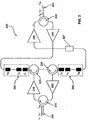
- FIG. 2 is a block diagram of a bidirectional optical amplifier module 200 consistent with the present invention.
- Module 200 includes two ports 205 and 260, four optical circulators 210, 225, 230, and 245, four optical amplifiers 215, 220, 235, and 240, and two groups of in-fiber Bragg gratings 250 and 255.
- Module 200 generally provides a concise apparatus and method for bidirectionally amplifying interleaved channels and may be located within the transmission path of a larger WDM system.
- ports 205 and 260 in module 200 may be connected to optical transmission fiber for a WDM ring network or for a long-distance link within a multi-link WDM system, such that module 200 serves as one of a plurality of optical line amplifier sections in an overall WDM optical transmission system.
- Port 205 is coupled to receive a first group of channels traveling in an inbound or east direction. As shown in Fig. 2, the first group corresponds to a first series of wavelengths indicated with odd-numbered subscripts ⁇ 1 , ⁇ 3 , ..., ⁇ 31 and representing odd channels. Similar to port 205, port 260 is coupled to receive a second group of channels traveling in an outbound or west direction. The second group of channels, however, corresponds to even-numbered wavelengths indicated with even-numbered subscripts ⁇ 2 , ⁇ 4 , ..., ⁇ 32 . The second or even group preferably includes the same number of channels as the odd group. In addition, the channels of the even group are preferably interleaved with the channels of the odd group.
- the even-numbered wavelengths are selected so that they are staggered with respect to the odd-numbered wavelengths.
- a select number of wavelengths in either the odd or even wavelengths may not be available due to the configuration of the WDM system, however, in a preferred setup, each pair or wavelengths of one series, e.g. the odd wavelengths or channels, encompasses a wavelength of the other series.
- the wavelengths of the east and west series of wavelengths will be indicated as staggered, more generally, even when the wavelengths of the signals of each of the series are separated (in frequency) by a quantity greater than or equal to 2D, where D indicates the minimum bandwidth (in frequency) of the wavelength selective components used in the system to separate the signals at the various wavelengths.
- wavelengths of each series may be grouped together in respective multiple packets.
- the packets of channels in one series may then be interleaved with packets of channels from the other series, such that each pair of packets of one series encompasses a packet of the other series.
- the odd and even groups preferably have the same number of channels.
- the two groups although preferably including sixteen channels each, may include more or fewer channels.
- the number of wavelengths corresponding to the number of optical channels used for transmission in each direction may be selected in relation to the characteristics of the telecommunication system in which module 200 is implemented.
- the number of channels in the system may be increased to increase the transmitting capacity of the system, e.g. to accommodate an increased traffic demand.
- the useful amplification band of the amplifiers may also be constituted of two or more distinct spectral bands separated by spectral bands not well-suited for signal transmission or amplification, e.g. due to the particular spectral characteristics of the amplifiers or optical fibers employed in the telecommunication system.
- the wavelengths of the communication channels may, for example, be selected such that the corresponding frequencies are equally spaced within each individual spectral band, with the separation between adjacent channels propagating in the same direction greater than or equal (in frequency) to twice the value D.
- each of the channels in the odd group is separated by 200 GHz and each of the channels in the even group a separated by 200 GHz. Since the channels of both groups are preferably interleaved, a channel of one group would lie halfway in between a pair of channels in the other group. For example, ⁇ 2 would be 100 GHz below ⁇ 3 , and 100 GHz above ⁇ 1 . Note that since the speed of light, c, is equal to the product of channel wavelength and channel frequency, the above separations could also be determined by wavelength. The channels could also be unevenly spaced if desired, for instance to offset any four-wave mixing effects in the overall transmission system.
- ports 205 and 260 pass the odd group and even group of channels to optical circulators 210 and 245, respectively.
- Optical circulators 210, 225, 230, and 245 are each conventional three-port optical circulators. Each port of the circulator an both input and output a signal. In addition, as shown, each optical circulator transmits unidirectionally the radiation input at each of the ports to only the next circulator port in sequence. In the three-port circulators of Fig. 2, the rotational sequence is in a clockwise direction. Thus, a signal received at a port is input to the circulator at an input port and passed in a clockwise direction to the next port of the circulator, which outputs the signal.
- Optical circulators 210, 225, 230, and 245 are standard passive components in the optical communications field and can be obtained from several suppliers, such as JDS FITEL Inc., 570 Heston Drive, Nepean, Ontario (CA) or E-TEK DYNAMICS, Inc., 1885 Lundy Ave., San Jose, CA (USA).
- circulators for use with the present invention are of the polarization-independent type.
- Optical circulators 210 and 245 circulate and output the odd group and even group of channels to amplifiers 215 and 240, respectively.
- Amplifiers 215, 220, 235, and 240 of module 200 am preferably erbium-doped fiber amplifiers Aluminum, germanium, and lanthanum, or aluminum and germanium, may be advantageously used as secondary doping agents. The concentration of dopants may correspond, for example, to an attenuation of around 7 dB/m, for the active fiber in the absence of pumping.
- the amplifier described uses erbium-doped adtive fibers of the type presented in detail in patent application EP 677902, in the name of the Applicant, which is herein incorporated by reference.
- Each amplifier is pumped, for example, by one or more laser diodes (not shown) to provide optical gain to the signals it amplifies.
- the amplifiers provide optical gain to each of the channels to offset attenuation. However, in addition to providing the gain, the amplifiers also add noise, such as ASE, to the channels.
- Amplifier 215 amplifies and outputs the odd group of channels to optical circulator 225, which passes the odd group of channels to selective reflection filters 250.
- Amplifier 240 amplifies and outputs the even group of channels directly to selective reflection filters 250.
- Selective reflection filters 250 and 255 can be, for example, in-fiber Bragg gratings or Bragg filters having a plurality of Bragg gratings.
- Distributed Bragg reflection optical waveguide filters are an example of selective reflection filters adapted for use in the present invention. They reflect the radiation in a narrow wavelength band and transmit the radiation outside that band. Each of them comprises a section of an optical waveguide, e.g. an optical fiber, along which the refractive index shows periodical variations. If the signal portions reflected at each index change are in phase, constructive interference results and the incident signal is reflected.
- the periodical refractive index variation in the Bragg gratings can be achieved by known techniques, for example by exposing a section of an optical fiber, deprived of the protective coating, to the interference fringes formed by a strong UV beam (like the one generated by an excimer laser, a frequency-doubled argon laser, or a frequency-quadrupled Nd:YAG laser) put into interference with itself by an appropriate interferometric system, e.g. by a silicon phase mask, as described in U.S. Patent No. 5,351,321.
- Each grating only reflects light propagating through the fiber within a very narrow range around a central wavelength.
- Bragg grating filters can be obtained with a -0.5 dB band of reflected wavelengths that is typically only 0.3-0.4 nm wide and a -20 dB band of reflected wavelengths of about 1 nm or less, with reflectivity up to 99% in the centre of the band.
- a central wavelength change with temperature can be obtained not higher than 0.02 nm/°C. Due to possible temperature fluctuations, Bragg gratings 250 and 255 may be associated with a standard Peltier cell, which is a conventional temperature stabilization device readily known and available to those of ordinary skill in the art, or other conventional temperature stabilization means.
- the individual gratings within distributed Bragg grating 250 are set to reflect respectively each of the odd group of channels, but pass each of the even group of channels.
- the gratings of fiber gratings 255 are set to reflect each of the even group of channels and pass each of the odd group of channels.
- Each of the gratings may be chirped if desired, to compensate for dispersion.
- the center-band reflectivity may change from grating to grating, to flatten or otherwise shape the amplification spectrum.
- the gratings reflect the odd group of channels, but pass the signals located between the channels, which includes noise and ASE.
- the reflection of a channel by a fiber grating serves to eliminate noise ASE located between the channels, either created by amplifier 215 or due to back reflection of even channels at fiber interfaces, e.g. from Rayleigh back scattering.
- narrow-band Bragg gratings i.e. with a reflection band of less than 1 nm and preferably less than 0.5 nm
- the signal reflected by the fiber gratings reflects essentially only the data signals that correspond to the odd group of channels.
- Fiber gratings 250 are particularly advantageous in minimizing interferometric noise caused by reflections from fiber interfaces or Rayleigh back scattering, as discussed further below.
- Amplifier 240 After passing unreflected through fiber gratings 250, the ASE and other noise generated by amplifier 215 or caused by back reflection travels to the output of amplifier 240.
- Amplifier 240 preferably includes an isolator (not shown) positioned at its output that prohibits the passage of signals into amplifier 240.
- Opto-isolators are commonly available on the market from such suppliers as ISOWAVE, 64 Harding Avenue, Dover, NJ (USA). As a result, the ASE and other noise separated at fiber gratings 250 are extinguished by the isolator at amplifier 240.
- the odd group of channels After being reflected by gratings 250, the odd group of channels return to circulator 225 and rotate to the third port of the circulator. At this port, the odd group of channels exits and enters circulator 230 at a second port of that device. Circulator 230 ratates the odd group of channels to the next port, where they exit and pass into Bragg gratings 255. In contrast to Bragg gratings 250, filter 255 has Bragg gratings with reflection wavelengths equal to the even channels. As a result, the odd channels entering filter 255 from circulator 230 pass through filter 255 and proceed to the next amplifier 235.
- filter 255 acts as a notch filter to remove any additional ASE or other type of noise present in the narrow bands between the odd channels, i.e. the wavelengths corresponding to the even channels, which prevents generation of any substantial amount of interferometric noise, and allows operation of the amplifier with a dense channel spacing.
- Fiber amplifier 235 which preferably although not restrictively is doped with erbium, further amplifies the odd channels and is optional to the performance of the present invention.
- amplifier 235 includes at least one laser diode source for providing pumping radiation, typically of either 980 nm or 1480 nm, for the amplifier.
- amplifier 235 may comprise a single-stage or a multi-stage configuration, depending on the system requirements.
- amplifier 235 may have an opto-isolator (not shown) positioned at its input to prohibit unwanted reflections or similar noise from entering the amplifier.
- amplifier 235 operates in a saturated condition. This mode of operation for amplifier 235 helps to create an increased power boost to the odd channels before they exit module 200. As well, operating amplifier 235 in saturation will minimize the amount of ASE generated by that amplifier. In a saturated condition, amplifier 235 operates with a lower gain, which results in less ASE. Alternatively, a filter could be added after the output of amplifier 235 to remove ASE generated by this second amplifier for the odd channels, but the addition of such a filter adds attenuation to the overall amplifier module.
- Port 260 may be connected to the optical transmission path (not shown) of a WDM system for transmitting the amplified odd channels.
- even channels ⁇ 2 , ⁇ 4 , ..., ⁇ 32 enter module 200 from port 260 and travel east to west in Fig. 2. These even channels undergo similar filtering and amplification in module 200 as do the odd channels.
- circulator 245 rotates the received even channels from port 260 to the next clockwise port, where they exit.
- the even channels then enter amplifier 240, which provides amplification to the even channels while operating in a linear mode but also introduces unwanted ASE and other noise.
- amplifier 240 is a rare-earth doped fiber amplifier, preferably doped with erbium, and may comprise a single-stage or multi-stage amplifier as needed.
- filter 250 is a selective reflection filter that preferably is a Bragg filter having a plurality of Bragg gratings at predetermined centre wavelengths that correspond to the odd channel wavelengths.
- fitter 250 acts as a notch filter for the even wavelengths and improves the isolation from unwanted reflections of the odd channels at ports 260, 205, e.g. due to Rayleigh back scattering.
- the even channels pass through filter 250 and enter circulator 225, which rotates them clockwise to the next port and outputs them to circulator 230. Circulator 230 in turn performs the same function and outputs the even channels to filter 255.
- filter 255 is also a selective reflective filter that preferably is a Bragg filter having a plurality of Bragg gratings at predetermined center wavelengths that correspond to the even channel wavelengths. Consequently, filter 255 reflects the even channels and a narrow band, i.e. less than 1 nm and preferably less than 0.5 nm, back to circulator 230 and passes all other signals. ASE accumulated from amplifier 240 and other noise is therefore removed from the even channels. The even wavelengths are then rotated clockwise in circulator 230 and exit into amplifier 220.
- amplifier 220 which preferably although not restrictively is doped with erbium, further amplifies the channels and is optional to the performance of the present invention.
- amplifier 220 includes at least one laser diode source for providing pumping radiation, typically of either 980 nm or 1480 nm, for the amplifier.
- amplifier 220 may comprise a single-stage or a multi-stage configuration, depending on the system requirements.
- amplifier 220 operates in a saturated condition. This mode of operation for amplifier 220 helps to create an increased power boost to the even channels before they exit module 200. As well, operating amplifier 220 in saturation will minimize the amount of ASE generated by that amplifier. In a saturated condition, amplifier 220 operates with a lower gain, which results in less ASE. Alternatively, a filter could be added after the output of amplifier 220 to remove ASE generated by this second amplifier for the even channels, but the addition of such a filter adds attenuation to the overall amplifier module.
- Applicants have found that despite the use of fiber gratings 250 and 255 to remove ASE and other noise and provide better channel-to-channel isolation, oscillation or ringing at wavelengths outside the bandwidth of the WDM system may arise due to reflections at port 260. Moreover, Applicants have found that by using ASE peak suppression filter 257, which is positioned between fiber gratings 255 and amplifier 235, possible loss of output power for module 200 is prevented.
- amplifier 240 generates ASE and other noise that are at wavelengths outside both the odd and even channel wavelengths of the WDM system. While fiber gratings 250 and 255 help to improve the channel-to-channel isolation for the even channels as they pass to the second amplifier 220, these gratings do not filter out noise at wavelengths that are higher than the highest even channel wavelength or lower than the lowest even channel wavelength. These extreme noise wavelengths pass through fiber gratings 250, circulators 225 and 230, and fiber gratings 255. Additional ASE noise is generated by amplifier 235. ASE peak suppression filter 257, however, removes these extreme noise wavelengths from module 200. ASE filter, or another filter in series with ASE filter (not shown), may also remove ASE at wavelengths that are not used for transmission (if any) if no grating is provided at those wavelengths, so as to keep ASE power low.
- ASE peak suppression filter 257 effectively removes the extreme noise wavelengths and avoids any ringing. The placement of ASE peak suppression filter 257 between amplifiers 215 and 235 ensures that the second amplifier 235 can compensate for the loss of power caused by filter 257.
- module 200 Due to the layout of module 200, only one ASE peak suppression filter 257 is required.
- noise at wavelengths that are higher than the highest odd channel wavelength or lower than the lowest odd channel wavelength generated by amplifier 215 rotate through circulator 225 and pass through fiber gratings 250.
- the isolator (not shown) at the output of amplifier 240 blocks the passage of all wavelengths including the extreme noise wavelengths. As a result, ringing or oscillation caused by a loop-back of reflections from port 205 does not exist as it may at port 260 on the even channel input side.
- Fig. 3 shows a graph of test results for module 200 without filter 257, which illustrates the deleterious oscillation present on the even channel line.
- plot 310 corresponds to the output obtained from module 200 when operated in a WDM system operating with four even channels 320, 330, 340, and 350.
- the loop-back of noise at wavelengths beyond the channel wavelengths causes a ringing depicted by 360 in Fig. 3.
- ASE peak suppression filter 257 was added in module 200.
- Plot 395 in Fig.3 shows the odd channels that are traveling in the opposite direction in module 200.
- the odd channels in the test setup for Fig. 3 had three channels designated as 380, 385, and 390 as shown on plot 395. Addition of an ASE peak suppression filter avoids the oscillation 360 and improves the output power the channels and the signal-to-noise ratio.
- the optical arrangement of the present invention helps to minimize interferometric noise caused by back reflections such as Rayleigh back scattering or reflections from fiber interfaces.
- amplified signals traveling eastbound and exiting amplifier module 200 at circulator 245 and westbound signals exiting the module at circulator 210 may lead to reflections, or echoes, at interfaces with optical fiber at ports 205 and 260, respectively.
- echo signals as described may also arise from Rayleigh back scattering from optical fiber lines attached to module 200.
- the eastbound, or odd, channels may cause echoes at the odd wavelengths that pass from port 260 into circulator 245. These odd-wavelength echoes will mix with the even channels traveling westbound in amplifier module 200.
- fiber gratings 250 will help to remove these odd-wavelength echoes in a manner described above. Similarly, fiber gratings 250 will pass even-wavelength echoes that re-enter module 200 via circulator 210, so that the even-wavelength echoes are dissipated by the isolator (not shown) coupled to the output of fiber amplifier 240.
- module 200 a preferred combination of components for module 200 will ensure that any echo signals have power difference of 26 dB below the corresponding channel wavelengths so that interferometric noise in module 200 is avoided.
- One of ordinary skill in the art will understand that a selection of appropriate devices for the amplifiers, circulators, gratings, etc. of module 200 can readily be accomplished to achieve a 26 dB difference.
- each fiber grating contributes to filtering both during reflection and during transmission, what helps to avoid interferometric noise while providing clean wavelength regions between channels for isolation so that narrower channel-to-channel spacing can be attained in a bidirectional amplification system in comparison with systems using fiber gratings only as reflection filters.
- Fig. 4 illustrates an expected performance of module 200 for two representative channels 110 and 120 of a WDM system, as measured along the fiber connecting circulators 225 and 230.
- the fiber gratings in module 200 filter out much of the ASE noise surrounding the channels.
- the gratings however, have a bandwidth wider than the signal width so that the gratings do not eliminate any of the information from the channels.
- Curve 100 in Fig. 4 shows the remaining ASE spectrum remaining around channels 1 and 3.
- Fig. 4 shows the elimination of unwanted ASE 100 or other noise at wavelengths between the two channels wavelengths.
- this filtering improves the isolation for the channels as compared with their echo due to back reflection at ports 260 and 205 and helps with error-free detection of the channels at a receiver downstream from module 200 in the WDM system. Furthermore, the ASE power level is reduced in comparison to conventional techniques, which leads to an increase of pumping power available to amplify the signals and to an increased gain and signal-to-noise ratio.
- module 200 includes four optical circulators, each having three ports. However, other designs may include a different number of optical circulators having the same or different number of ports.
- Fig. 5 is a block diagram of another bidirectional optical amplifier module 500, consistent with the present invention, having a different number of optical circulators with a different number of ports than module 200.
- module 500 includes only three optical circulators 510, 525, and 550. Also, optical circulator 525 includes four ports, whereas optical circulators 510 and 550 each include three ports. However, like module 200, module 500 includes two ports 505 and 555, four amplifiers, 515, 520, 540, and 545, and two group of fiber gratings 530 and 535.
- Module 500 operates very similarly to module 200. Like module 200, module 500 receives the odd group of channels, which travel in an easterly or inbound direction at part 505 and the even group of channels, which travel in a westerly or outbound direction, at part 555. Ports 505 and 555 pass the odd group and even group of channels to optical circulators 510 and 550, respectively, which in turn pass the channels to amplifiers 515 and 545, respectively. The amplified odd group of channels then passes through optical circulator 525 to fiber gratings 535. The amplified even group of channels passes directly to fiber gratings 535.
- Fiber gratings 535 includes gratings to reflect only signals with frequencies corresponding to the odd group of channels. Thus, fiber gratings 535 reflect the odd group of channels, but pass the even group of channels. Both group of channels then pass through optical circulator 525 to fiber gratings 530, which include gratings to reflect only signals with frequencies corresponding to the even group of channels. Consequently, fiber gratings 530 reflect the even group of channels and pass the odd group of channels.
- the reflected even group of channels rotates through optical circulator 525 to amplifier 520, and the odd group of channels passed by fiber gratings 530 propagates into amplifier 540 via ASE peak suppression filter 537.
- Amplifiers 520 and 540 amplify and pass the even group and odd group of channels through optical circulators 510 and 550 to ports 505 and 555, respectively.
- filter 537 in module 500 avoids ringing or oscillation from occurring due to loop-back of ASE reflections form port 555. Consequently, the grating reflectors 535 and 530, together with ASE peak suppression filter 537 and circulator 525, serve as a filtering device between the respective two-stage amplifiers used for the odd and even groups of channels.
- the present invention provides a succinct structure for amplifying and filtering bidirectional, interleaved channels in a WDM system.
- the bidirectional amplifier and filter of the present invention helps to improve the signal-to-noise ratio of the channels in the WDM system, which leads to improved detection of the information channels by a downstream receiver.
- reflection noise causing oscillation between connections at the input/output ports of the amplifier module is reduced due to improved isolation.
- isolation of channels with respect to their echo due to back reflection or back scattering is improved.
Landscapes
- Engineering & Computer Science (AREA)
- Computer Networks & Wireless Communication (AREA)
- Signal Processing (AREA)
- Physics & Mathematics (AREA)
- Electromagnetism (AREA)
- Lasers (AREA)
- Optical Communication System (AREA)
Priority Applications (1)
| Application Number | Priority Date | Filing Date | Title |
|---|---|---|---|
| EP98123903A EP0928081B1 (fr) | 1997-12-31 | 1998-12-16 | Système de transmission optique bidirectionnel pour multiplexage en longeur d'onde dense entrelacé |
Applications Claiming Priority (3)
| Application Number | Priority Date | Filing Date | Title |
|---|---|---|---|
| EP97123014 | 1997-12-31 | ||
| EP97123014 | 1997-12-31 | ||
| EP98123903A EP0928081B1 (fr) | 1997-12-31 | 1998-12-16 | Système de transmission optique bidirectionnel pour multiplexage en longeur d'onde dense entrelacé |
Publications (2)
| Publication Number | Publication Date |
|---|---|
| EP0928081A1 true EP0928081A1 (fr) | 1999-07-07 |
| EP0928081B1 EP0928081B1 (fr) | 2004-11-17 |
Family
ID=26146030
Family Applications (1)
| Application Number | Title | Priority Date | Filing Date |
|---|---|---|---|
| EP98123903A Expired - Lifetime EP0928081B1 (fr) | 1997-12-31 | 1998-12-16 | Système de transmission optique bidirectionnel pour multiplexage en longeur d'onde dense entrelacé |
Country Status (1)
| Country | Link |
|---|---|
| EP (1) | EP0928081B1 (fr) |
Cited By (3)
| Publication number | Priority date | Publication date | Assignee | Title |
|---|---|---|---|---|
| WO2002067467A1 (fr) * | 2001-02-16 | 2002-08-29 | Future Fibre Technologies Pty Ltd | Systeme de communication optique |
| WO2004028056A1 (fr) * | 2002-09-18 | 2004-04-01 | The University Of Melbourne | Structure d'amplification et/ou d'insertion/extraction optique(s) amelioree(s) |
| KR100539901B1 (ko) * | 2002-12-11 | 2005-12-28 | 삼성전자주식회사 | Bpsr 광 전송 노드 |
Citations (3)
| Publication number | Priority date | Publication date | Assignee | Title |
|---|---|---|---|---|
| EP0724314A1 (fr) * | 1995-01-27 | 1996-07-31 | PIRELLI CAVI S.p.A. | Système de télécommunication optique bidirectionnel comprenant un amplificateur optique bidirectionnel |
| EP0729248A2 (fr) * | 1995-02-23 | 1996-08-28 | AT&T Corp. | Communication multiple à fibre optique |
| GB2304248A (en) * | 1995-08-07 | 1997-03-12 | France Telecom | Optical amplifier for bidirectional wavelength division multiplex communications |
-
1998
- 1998-12-16 EP EP98123903A patent/EP0928081B1/fr not_active Expired - Lifetime
Patent Citations (3)
| Publication number | Priority date | Publication date | Assignee | Title |
|---|---|---|---|---|
| EP0724314A1 (fr) * | 1995-01-27 | 1996-07-31 | PIRELLI CAVI S.p.A. | Système de télécommunication optique bidirectionnel comprenant un amplificateur optique bidirectionnel |
| EP0729248A2 (fr) * | 1995-02-23 | 1996-08-28 | AT&T Corp. | Communication multiple à fibre optique |
| GB2304248A (en) * | 1995-08-07 | 1997-03-12 | France Telecom | Optical amplifier for bidirectional wavelength division multiplex communications |
Non-Patent Citations (1)
| Title |
|---|
| SEIKAI S ET AL: "NOVEL OPTICAL CIRCUIT SUITABLE FOR WAVELENGTH DIVISION BIDIRECTIONAL OPTICAL AMPLIFICATION", ELECTRONICS LETTERS, vol. 29, no. 14, 8 July 1993 (1993-07-08), pages 1268 - 1270, XP000322267 * |
Cited By (3)
| Publication number | Priority date | Publication date | Assignee | Title |
|---|---|---|---|---|
| WO2002067467A1 (fr) * | 2001-02-16 | 2002-08-29 | Future Fibre Technologies Pty Ltd | Systeme de communication optique |
| WO2004028056A1 (fr) * | 2002-09-18 | 2004-04-01 | The University Of Melbourne | Structure d'amplification et/ou d'insertion/extraction optique(s) amelioree(s) |
| KR100539901B1 (ko) * | 2002-12-11 | 2005-12-28 | 삼성전자주식회사 | Bpsr 광 전송 노드 |
Also Published As
| Publication number | Publication date |
|---|---|
| EP0928081B1 (fr) | 2004-11-17 |
Similar Documents
| Publication | Publication Date | Title |
|---|---|---|
| US6160660A (en) | Bidirectional optical transmission system for dense interleaved wavelength division multiplexing | |
| US6414769B1 (en) | Bidirectional multichannel optical telecommunication system | |
| US6437888B1 (en) | Device for adding and dropping optical signals | |
| US6259555B1 (en) | Multi-band amplification system for dense wavelength division multiplexing | |
| US5701194A (en) | Amplified telecommunication system for wavelength-division multiplexing transmissions capable of limiting variations in the output power | |
| US5598294A (en) | Optical fiber amplifier and optical fiber communication system | |
| JPH09244079A (ja) | 利得等化器及び光伝送システム | |
| EP1069712B1 (fr) | Amplificateur optique à large bande | |
| PL180797B1 (pl) | Sposób i układ do redukcji zakłóceń optycznych, wynikających z mieszania czterofalowego | |
| US20010024542A1 (en) | Method and device for dropping optical channels in an optical transmission system | |
| EP1088417B1 (fr) | Procede et dispositif de derivation de canaux optiques dans un systeme de transmission optique | |
| KR19990065030A (ko) | 하나의 도파관열 격자 다중화기를 이용한 양방향 애드/드롭 광증폭기 모듈 | |
| US6359728B1 (en) | Pump device for pumping an active fiber of an optical amplifier and corresponding optical amplifier | |
| EP0928081B1 (fr) | Système de transmission optique bidirectionnel pour multiplexage en longeur d'onde dense entrelacé | |
| EP0766423A2 (fr) | Système de transmission optique à multiplexage en longueur d'onde | |
| EP0989693A1 (fr) | Système d'amplification optique comprenant une fibre codopée Erbium-Ytterbium | |
| US6353497B1 (en) | Integrated modular optical amplifier | |
| US6690685B1 (en) | Method for producing a fiber laser | |
| AU9817298A (en) | Bidirectional optical transmission system for dense interleaved wavelength division multiplexing | |
| US6697575B1 (en) | System and method for increasing capacity of long-haul optical transmission systems | |
| KR20000023409A (ko) | 광 증폭 장치 및 광 전송 시스템 | |
| EP0989638A1 (fr) | Dispositif pour le pompage d'un amplificateur optique à fibre | |
| US7145716B2 (en) | Multiple stage Raman optical amplifier | |
| JPH08111550A (ja) | 光ファイバ増幅器および光ファイバ伝送システム | |
| CA2282940A1 (fr) | Appareil de pompage pour le pompage d'une fibre active d'amplificateur optique et amplificateur optique associe |
Legal Events
| Date | Code | Title | Description |
|---|---|---|---|
| PUAI | Public reference made under article 153(3) epc to a published international application that has entered the european phase |
Free format text: ORIGINAL CODE: 0009012 |
|
| AK | Designated contracting states |
Kind code of ref document: A1 Designated state(s): DE ES FR GB IT |
|
| AX | Request for extension of the european patent |
Free format text: AL;LT;LV;MK;RO;SI |
|
| AKX | Designation fees paid |
Free format text: AT BE CH CY DE LI |
|
| 17P | Request for examination filed |
Effective date: 19991222 |
|
| RBV | Designated contracting states (corrected) |
Designated state(s): DE ES FR GB IT |
|
| RAP1 | Party data changed (applicant data changed or rights of an application transferred) |
Owner name: OPTICAL TECHNOLOGIES U.S.A. CORP. |
|
| RAP1 | Party data changed (applicant data changed or rights of an application transferred) |
Owner name: CORNING O.T.I., INC. |
|
| 17Q | First examination report despatched |
Effective date: 20031017 |
|
| GRAP | Despatch of communication of intention to grant a patent |
Free format text: ORIGINAL CODE: EPIDOSNIGR1 |
|
| RAP1 | Party data changed (applicant data changed or rights of an application transferred) |
Owner name: CORNING PHOTONIC TECHNOLOGIES INC. |
|
| RIN1 | Information on inventor provided before grant (corrected) |
Inventor name: PICIACCIA, STEFANO Inventor name: MELI, FAUSTO Inventor name: AINA, STEFANO |
|
| GRAS | Grant fee paid |
Free format text: ORIGINAL CODE: EPIDOSNIGR3 |
|
| GRAA | (expected) grant |
Free format text: ORIGINAL CODE: 0009210 |
|
| AK | Designated contracting states |
Kind code of ref document: B1 Designated state(s): DE ES FR GB IT |
|
| REG | Reference to a national code |
Ref country code: GB Ref legal event code: FG4D |
|
| PGFP | Annual fee paid to national office [announced via postgrant information from national office to epo] |
Ref country code: GB Payment date: 20041119 Year of fee payment: 7 |
|
| PGFP | Annual fee paid to national office [announced via postgrant information from national office to epo] |
Ref country code: FR Payment date: 20041123 Year of fee payment: 7 |
|
| PGFP | Annual fee paid to national office [announced via postgrant information from national office to epo] |
Ref country code: ES Payment date: 20041216 Year of fee payment: 7 |
|
| REF | Corresponds to: |
Ref document number: 69827596 Country of ref document: DE Date of ref document: 20041223 Kind code of ref document: P |
|
| PGFP | Annual fee paid to national office [announced via postgrant information from national office to epo] |
Ref country code: DE Payment date: 20041230 Year of fee payment: 7 |
|
| PG25 | Lapsed in a contracting state [announced via postgrant information from national office to epo] |
Ref country code: ES Free format text: LAPSE BECAUSE OF FAILURE TO SUBMIT A TRANSLATION OF THE DESCRIPTION OR TO PAY THE FEE WITHIN THE PRESCRIBED TIME-LIMIT Effective date: 20050228 |
|
| PLBE | No opposition filed within time limit |
Free format text: ORIGINAL CODE: 0009261 |
|
| STAA | Information on the status of an ep patent application or granted ep patent |
Free format text: STATUS: NO OPPOSITION FILED WITHIN TIME LIMIT |
|
| ET | Fr: translation filed | ||
| 26N | No opposition filed |
Effective date: 20050818 |
|
| PG25 | Lapsed in a contracting state [announced via postgrant information from national office to epo] |
Ref country code: IT Free format text: LAPSE BECAUSE OF NON-PAYMENT OF DUE FEES Effective date: 20051216 Ref country code: GB Free format text: LAPSE BECAUSE OF NON-PAYMENT OF DUE FEES Effective date: 20051216 |
|
| PG25 | Lapsed in a contracting state [announced via postgrant information from national office to epo] |
Ref country code: DE Free format text: LAPSE BECAUSE OF NON-PAYMENT OF DUE FEES Effective date: 20060701 |
|
| GBPC | Gb: european patent ceased through non-payment of renewal fee |
Effective date: 20051216 |
|
| PG25 | Lapsed in a contracting state [announced via postgrant information from national office to epo] |
Ref country code: FR Free format text: LAPSE BECAUSE OF NON-PAYMENT OF DUE FEES Effective date: 20060831 |
|
| REG | Reference to a national code |
Ref country code: FR Ref legal event code: ST Effective date: 20060831 |