EP0928151B1 - Appareil manuel pour le nettoyage de surfaces lisses - Google Patents
Appareil manuel pour le nettoyage de surfaces lisses Download PDFInfo
- Publication number
- EP0928151B1 EP0928151B1 EP98943794A EP98943794A EP0928151B1 EP 0928151 B1 EP0928151 B1 EP 0928151B1 EP 98943794 A EP98943794 A EP 98943794A EP 98943794 A EP98943794 A EP 98943794A EP 0928151 B1 EP0928151 B1 EP 0928151B1
- Authority
- EP
- European Patent Office
- Prior art keywords
- wiper bar
- tool according
- edge
- manual tool
- wiper
- Prior art date
- Legal status (The legal status is an assumption and is not a legal conclusion. Google has not performed a legal analysis and makes no representation as to the accuracy of the status listed.)
- Expired - Lifetime
Links
Images


Classifications
-
- A—HUMAN NECESSITIES
- A47—FURNITURE; DOMESTIC ARTICLES OR APPLIANCES; COFFEE MILLS; SPICE MILLS; SUCTION CLEANERS IN GENERAL
- A47L—DOMESTIC WASHING OR CLEANING; SUCTION CLEANERS IN GENERAL
- A47L1/00—Cleaning windows
- A47L1/06—Hand implements
Definitions
- the invention relates to a hand-held device for cleaning smooth surfaces, especially glass panes, with a sponge block, a flat box-shaped the sponge block and parallel to it at a distance a wiper strip interchangeably receiving holder with a a direction of pull on it, one Wiper strip edge of the wiper strip over a cover wall of the holder diagonally to the front, to the side in the pulling direction, for example in the open Surface of the sponge block lying, protruding, with the holder each between the wiper strip and the sponge side walls has that from a plane that from the wiper edge and a free one that touches the surface to be cleaned Sponge block side is formed, lie back.
- Such handheld devices for cleaning smooth surfaces are from the EP 0 263 456 B1 known.
- This handheld device has the disadvantage that the distance between the top wall and the free front edge the wiper strip is constant, therefore occurs when cleaning modern ones Windows, usually in a rubber or silicone frame are held, which is about 1 cm far from the pane in the frame extends to the problem that when cleaning the frame-side track the wiper strip corner due to high friction values held back on the rubber and bent up so that a 1 cm wide glass edge strip remains moist and the from the wiper strip, which is usually held at a slight angle, on the side liquid displaced to the frame from the resulting gap increasingly flows down.
- the object of the invention is a hand-held device of the type mentioned Kind, while avoiding the aforementioned disadvantages, with simpler To improve shape change so that with the same smooth surfaces, like glass panes, without framing and without Liquid drain quickly and inexpensively even in the Edge areas of the surfaces can be cleaned satisfactorily.
- the side walls in one area near the wiper strip each has a side wall projection have that with a side wall edge close to said Level and the top wall in two of the wiper strips assigned corner areas up to close to the wiper edge
- Formation of stabilizing lugs for the wiper strip preferred is and the side wall edges at the front at the top of the stabilization tabs end there.
- the distance between the top wall and the front wiper strip edge over the length of the wiper strip different; In the corner areas of the top wall, the distance is too the wiper edge is smaller than the one in between Middle area and is about 2 mm to an elastic Adjustment to the rest of the wiping edge course with slight ease To ensure pressure.
- a Lift the wiper edge off the surface of the glass pane forming gaps between the surface of the Glass pane and the wiper strip are prevented.
- the stabilizing lugs are a plastic holder to the corner areas of the cover wall on the wiper strip side formed.
- Handheld devices with a holder made of metal are the Stabilizing lugs formed from the top wall, i.e. in the corner area of the top wall are the stabilizing noses punched out and then into their corresponding position pre-bent.
- An advantageous embodiment is that the two Side walls of the box-shaped housing one each have the adjacent recess, by which the wiper strip is edged on the side and from the this forward to the side over the side wall with a short Side area protrudes.
- the short side protrusion of the wiper strip is advantageous held in the side groove so that it is also at a Do not touch an inhibiting frame gasket rubber significantly bends away and the cleaning water towards the seal seals when the window pane in the frame area is subtracted.
- the wiper strip By protruding the wiper strip from the it is box-shaped housing with a good grip in the slot easily possible, the pane also in the corner areas peel off cleanly. Since the wiper strip is only 1 - 2 mm from the Recesses in the side walls, it will kept dimensionally stable. The problem of bending the Wiper strip ends with an escapement on the edging rubber the window is avoided.
- the distance between the front edge of the front wall and the front edge of the wiper strip larger in the central area than in the corner areas; there it is still about 2 mm, which makes an elastic adjustment over the entire course of the wiping edge with only slight pressure is to be guaranteed. Even when touching The wiper strip lies completely in the seals in the window frame on the glass pane, and a lifting of the wiper edge from the surface of the glass sheet to form Gaps between the surface of the glass sheet and the Wiper strip is prevented.
- the in the corner area of the Stabilizing lugs arranged on the top wall press the Wiper strip up to close to the side ends of the Glass pane surface, so that the wiper strip is even overall rests on the surface of the glass pane and thus the Cleaning liquid or the water and foam without problems, is removable from the surface without streaking.
- the elastic wiper strip is in the pull-off direction stabilized on the back of the side wall of the holder and in the direction of pressure from the back of the slot supported.
- This back is preferably on the rear bevel of the wiper strip adapted in shape.
- the bevel of the wiper strip is either up to the Wiping edge continued or the wiper strip is perpendicular to Wiping edge supported so that it protrudes trapezoidal.
- the supporting side wall is preferably almost to the Wiper edge brought up and closer to this by 1 - 2 mm than the stabilizing noses.
- the stabilizing lugs to the corner areas of the cover wall on the wiper strip side formed.
- the side walls of the stabilizing nose out towards the free Sponge surface from the disc level one to cleaning surface running backwards, i.e. with a recess, educated.
- a relatively large distance of about 5 - 6 cm between the Having a wiper edge up to the sponge is that Deposit the sponge from a deep frame drawn wiper edge up to the seal advantageously possible.
- the deep-drawn wiper strip side Side wall is angled approximately parallel to the wiper strip or Continued T-shaped, so that a U-shaped receiving chamber behind the wiper strip for stripped liquid and foam arises, which concentrate there without running off.
- the chamber walls are about 1 - 2 mm above the glass pane, depending on the pressure exerted when wiping closer. Because the drainage and wiping movement are dynamic Operations, the relatively wide gap in the side wall is sufficient up to the surface to be cleaned, the water and the foam always to capture and prevent it from draining.
- 1 to 8 is a (1) designated handheld for Cleaning smooth surfaces, especially glass panes (GS), shown, the holder (2) with a receptacle for a Wiper strip (4) and at least one sponge block (5) is flat box-shaped.
- the Holder (2) also any other elongated housing shape exhibit; a completely closed on the side, However, the housing is partially open on the cleaning side advantageous.
- a handle (6) On a top wall (3) of the holder (2) there is a handle (6) established. Depending on the material of the holder (2) this handle (6) is integrally formed on the holder (6) or held in the top wall (3) with a snap connection.
- the sponge block (5) preferably consists of two different hard sponge parts, of which the Wiper strip (4) facing away from the sponge part is harder and therefore brings about a stronger rubbing and cleaning effect.
- Both the wiper strip (4) and the sponge block (5) are from an open one, the wiper strip (4) and the sponge block (5) pointing holder side, which at the same time the Forms the cleaning side of the hand-held device (1) into the holder (2) used.
- the wiper strip (4) stands over the top wall (3) of the holder (2) before, the wiper strip (4) then becoming one cleaning surface (GS) is set at an acute angle.
- the distance in the Corner areas is about 2 mm and in the middle 5 - 10 mm, preferably 7 mm.
- the stabilizing lugs (7) hold the wiper strip (4) when Clean in position to the surface to be cleaned, so that also when wiping the side window rubber seals (GD) and at the same time on the surface to be cleaned (GS) Ends (4E) of the wiper strip (4) towards the surface are held down.
- the wiper strip (4) lies flat at all times on the surface of the surface to be cleaned, in particular also in the edge area on the window frame side up to the touched Seal (GD) of the window frame (R).
- the stabilizing lugs (7) are made of plastic existing top wall (3) of the holder (2) formed.
- the side walls (2S) in the area near the sponge are about 1 - 2 cm narrow and in the area close to the bar up to almost that Wiper strip edge level preferred and form one Sidewall projection (2V).
- the front edge (2K) of the The protrusion preferably runs slightly closer to Wiper edge (4K) or in continuation of the tip of the Stabilizing nose (7) towards the sponge (5), however, the distance to the surface to be cleaned (GS) is slight increases, which lies approximately in the plane (E), which of the Wiper edge (4K) and the free sponge surface formed is.
- the side wall protrusion (2V) sits about 1 - 2 cm from the Wiper strip (4) continues in the sponge direction, the rest of the larger one Side wall area (2S) up to the sponge (5) is stronger pulled in so that the sponge (5) from the frame (R) one Window can be lifted out, the Wiper strip edge (4K) remains on the window (GS) and is drawn close to the frame (R) and the one there Gasket (GD).
- the side wall projection (2V) With the side wall projection (2V) the stripped Liquid and foam prevented from flowing out.
- a retaining wall (T) in the holder interior about 1 - 2 cm long, so that a U-shaped Collection chamber is formed by the wiper strip (4), the Sidewall projection (2V) and the support wall (T) is surrounded.
- the side wall (2S *) is a modified version in Continuation of the support wall (T) angled.
- All guiding, fixing and stabilizing elements are included the holder housing (2) integrated made of plastic.
- the wiper strip (4) only protrudes at the front beyond the front wall (SV) of the housing (2).
- the wipers according to the invention have the two Side walls (2V) of the box-shaped housing (2) each one Narrow adjoining the stabilizing nose (7) Recess (8.8A) through which the wiper strip (4) only a short piece with its ends (4E, 4T) laterally over the Wiper housing side wall (2V) protrudes.
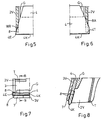
- Fig. 5 shows a section of a first embodiment of a groove-like recess (8) of the side wall (2V) along the Wiper strip (4) cut.
- the recess widens to Front so that the side wall (2V) that the rear wall (R) the groove (8) forms, tapering to the front.
- the rear wall (WR) supports the wiper strip (4) against the Contact pressure on the wiper edge (4K) when wiping off.
- the side surface of the wiper strip (4) runs the slope of the Rear wall (WR) adjusted up to the wiper edge (4K) straight through, so that the wiper strip end (4E) tapers out the side wall (2V) protrudes laterally.
- Fig. 7 shows an end view of FIG. 5 on the Wiper edge (4K).
- the groove (8) holds the wiper strip (4) on the one hand with the side wall (2V) and on the other hand with the front support lug (7) of the front wall (3V).
- Side wall (2V) is on the inside of the housing (3)
- Counter holder (G) arranged with which the wiper strip (4) is pinched. This is an alternative to that in Fig. 2 shown bead holder.
- the retaining wall (T) forms one Bag with the side wall and the wiper strip to catch the stripped liquid.
- Fig. 8 shows a section BB through Fig. 7, in which the Front (3V) with the support nose (7) and the side wall (2V) with the groove (8) and the inserted wiper strip (4) see is. On the back is the latter by the counter holder (G) supported. You can see in the pocket with the retaining wall (T) into it.
- the side wall (2V) extends 1 - 2 mm to the Wiper strip edge (4K) and the support lug (7) is about 1 - 2 mm further back from this.
- FIG. 6 shows an alternative embodiment of the recess (8A), the slit-like side wall (2V) along the front wall interspersed so that the wiper strip (4) until shortly before trapezoidal laterally protruding wiper strip end area (4T) is held there in a loose fit.
- this side blunted squeegee can be an even larger side Amount of liquid when pulling along a frame dammed up and then transferred into the interior than at the tapered wiper strip end (4E) according to FIG. 5.
- FIGS. 7 and 8 also apply to the embodiment according to FIG. 6 to.
- FIG. 4 shows another embodiment of the hand-held device (1) shown with a cover wall (3) made of metal (M).
- the Stabilizing lugs (7) are from the top wall (3) of the holder (2) molded out.
- the top wall (3) is from the broad side of the hand-held device (1) cut into a short piece, and so free cut ends / corners (3E) of the top wall (3) then to form the stabilizing lugs (7) in Bent towards the wiper edge (4K).
- the holder (2) can be in its wiper strip-side corner areas (3E) other the ends (4E) the wiper strip (4) or position-fixing stabilizing Elements, such as projections or the like. Have.
Landscapes
- Cleaning Implements For Floors, Carpets, Furniture, Walls, And The Like (AREA)
Claims (16)
- Appareil manuel pour le nettoyage de surfaces lisses, tout particulièrement de vitres (GS), avec un bloc d'éponge (5), une monture en forme de caisson (2), qui accueille, de manière amovible, ledit bloc d'éponge (5) et une baguette de raclage (4) disposée parallèlement à distance de ce dernier, et avec une poignée (6) orientée dans une direction de traction, un bord (4K) de ladite baguette de raclage (4) faisant saillie obliquement, sur le devant, à l'opposé du sens de traction, au-delà de la surface de recouvrement (3) de la monture (2), sensiblement au niveau de la surface libre du bloc d'éponge (5), la monture (2) présentant entre la baguette de raclage (4) et l'éponge (5), des parois latérales (2S) qui sont situées en retrait par rapport à un plan (E) formé par le bord (4K) de la baguette de raclage (4) et un côté libre du bloc d'éponge entrant en contact avec la surface à nettoyer,
caractérisé en ce que les parois latérales (2S) présentent chacune, dans un secteur proche de la baguette de raclage, une saillie (2V) qui s'étend presque jusqu'au dit plan (E) avec un bord (2K) de la paroi latérale, que la surface de recouvrement (3) s'étend en avant, dans deux zones angulaires (3E), associées à la baguette de raclage (4), jusqu'à proximité du bord (4K) de ladite baguette de raclage, en formant des nez de stabilisation (7) pour la baguette de raclage (4) et que les bords (2K) des parois latérales se terminent chacun à la pointe du nez de stabilisation (7) y associé. - Appareil manuel selon la revendication 1, caractérisé en ce que les nez de stabilisation (7) sont formés à partir de la surface de recouvrement (3) en matière plastique (P) de la monture (2).
- Appareil manuel selon la revendication 1, caractérisé en ce que les nez de stabilisation (7) sont formés à partir d'une surface de recouvrement (3) en tôle métallique (M) de la monture (2).
- Appareil manuel selon la revendication 1, caractérisé en ce que le bord (2K) de la paroi latérale descend, en direction de l'éponge, en pente plane hors du plan (E).
- Appareil manuel selon l'une des revendications 1 à 4, caractérisé en ce qu'en retrait de chaque saillie (2V) de la paroi latérale, une paroi d'appui (T) est formée, orientée à peu près parallèlement au côté intérieur de l'éponge et forme, avec ladite saillie latérale (2V) et la baguette de raclage (4), une chambre en forme de V qui s'étend approximativement jusqu'audit plan (E).
- Appareil manuel selon la revendication 1 caractérisé en ce que le bord (2K) de la paroi latérale est distancé d'environ 2 mm dudit plan (E).
- Appareil manuel selon la revendication 5 caractérisé en ce que la saillie (2V) de la paroi latérale et la paroi d'appui (T) présentent chacune une largeur de 1 à 2 cm.
- Appareil manuel selon l'une des revendications 1 a 7, caractérisé en ce que les deux parois latérales (2V, 2S) de la monture en forme de caisson (2) présentent chacune un évidement (8, 8A) en prolongement d'un côté antérieur (3V), dans lequel la baguette de raclage (4) est enchâssée latéralement et hors duquel elle fait saillie en avant, latéralement, au-delà de la paroi latérale (2V, 2S), avec une courte zone latérale (4E, 4T).
- Appareil manuel selon la revendication 8, caractérisé en ce que la baguette de raclage (4) présente deux surfaces latérales obliques qui s'élargissent vers le bord de raclage frontal (4K) et que les évidements (8) sont conçus en forme de rainures dont la largeur correspond à peu près à l'épaisseur de la baguette de raclage, et que des côtés arrière (WR) desdites rainures, opposés au côté antérieur (3V) du boítier, divergent dans le sens avant, conformément aux bords lacéraux de la baguette de raclage, de sorte que la profondeur de la rainure augmente dans ce sens et que la paroi latérale (2S) se termine en pointe, en avant, à l'extrémité de ladite rainure.
- Appareil manuel selon la revendication 8 ou 9, caractérisé en ce que les zones latérales (4E) de la baguette de raclage (4), qui font saillie hors des évidements (8, 8A), présentent, vues frontalement, une forme triangulaire ou trapézoïdale.
- Appareil manuel selon la revendication 8, caractérisé en ce que l'évidement (8A) est conçu en forme de fente et reçoit de manière lâche la baguette de raclage (4) qui fait saillie latéralement hors dudit évidement (8A) et s'appuie en arrière dans ledit évidement (8A).
- Appareil manuel selon l'une des revendications 8 à 11, caractérisé en ce que la baguette de raclage (4) est pressée avec une baguette de serrage (G) contre les côtés antérieurs (3V) de la monture (2), jusqu'à proximité des saillies de parois latérales (2V), et y est maintenue.
- Appareil manuel selon l'une des revendications 8 à 12, caractérisé en ce que celui-ci présente une boíte qui est disposée parallèlement à la baguette de raclage (4) et dans laquelle un bloc d'éponge (5) interchangeable est logé.
- Appareil manuel selon l'une des revendications 8 à 13, caractérisé en ce que, sensiblement parallèle à la baguette de raclage (4), une paroi d'appui (T) est formée à chacune des parois latérales (2S) de sorte à former une coupelle collectrice en forme de U.
- Appareil manuel selon la revendication 5, caractérisé en ce qu'une parois latérale (2S*), faisant suite à chaque paroi d'appui (T), s'étend en formant un coude vers l'éponge.
- Appareil manuel selon l'une des revendications précédentes, caractérisé en ce que la saillie (2V) des parois latérales parvient jusqu'à 1 à 2 mm du bord de la baguette de raclage (4K) et que le bord (3V) de la surface de recouvrement, dans la zone de l'évidement (8), est en retrait de 1 à 2 mm de plus que ladite saillie (2V) du boru (4K) de la baguette de raclage.
Applications Claiming Priority (5)
| Application Number | Priority Date | Filing Date | Title |
|---|---|---|---|
| DE29713472U | 1997-07-29 | ||
| DE29713472U DE29713472U1 (de) | 1997-07-29 | 1997-07-29 | Handgerät zum Reinigen glatter Flächen |
| DE1998131899 DE19831899C2 (de) | 1998-07-16 | 1998-07-16 | Handgerät zum Reinigen glatter Flächen |
| DE19831899 | 1998-07-16 | ||
| PCT/EP1998/004727 WO1999005953A1 (fr) | 1997-07-29 | 1998-07-29 | Appareil manuel pour le nettoyage de surfaces lisses |
Publications (2)
| Publication Number | Publication Date |
|---|---|
| EP0928151A1 EP0928151A1 (fr) | 1999-07-14 |
| EP0928151B1 true EP0928151B1 (fr) | 2004-06-02 |
Family
ID=26047463
Family Applications (1)
| Application Number | Title | Priority Date | Filing Date |
|---|---|---|---|
| EP98943794A Expired - Lifetime EP0928151B1 (fr) | 1997-07-29 | 1998-07-29 | Appareil manuel pour le nettoyage de surfaces lisses |
Country Status (3)
| Country | Link |
|---|---|
| EP (1) | EP0928151B1 (fr) |
| DE (1) | DE59811510D1 (fr) |
| WO (1) | WO1999005953A1 (fr) |
Cited By (1)
| Publication number | Priority date | Publication date | Assignee | Title |
|---|---|---|---|---|
| EP3549503B1 (fr) * | 2016-12-02 | 2023-03-08 | Skybest Electric Appliance (Suzhou) Co., Ltd. | Tête de brosse d'absorption d'eau et aspirateur humide/sec doté de celle-ci |
Families Citing this family (3)
| Publication number | Priority date | Publication date | Assignee | Title |
|---|---|---|---|---|
| FI20020984A7 (fi) * | 2001-07-18 | 2003-01-19 | Inno Onni Oy | Laite ikkunoiden kuivaamiseksi |
| DE20114019U1 (de) * | 2001-08-24 | 2003-01-23 | Emmel, Mathias, 35390 Gießen | Gerät zum Reinigen glatter Flächen |
| DE102014116206B3 (de) * | 2014-11-06 | 2016-01-21 | Karl Göttler | Handreiniger |
Family Cites Families (4)
| Publication number | Priority date | Publication date | Assignee | Title |
|---|---|---|---|---|
| US1497933A (en) * | 1922-05-08 | 1924-06-17 | James M Oberti | Squeegee for floors |
| US2230583A (en) * | 1940-03-30 | 1941-02-04 | Borden Max | Squeegee |
| US3950813A (en) * | 1973-06-19 | 1976-04-20 | Buck S Keith | Squeegee |
| WO1988002615A1 (fr) * | 1986-10-07 | 1988-04-21 | Manfred Klotz | Appareil portatif pour nettoyer des surfaces lisses, notamment des vitres |
-
1998
- 1998-07-29 EP EP98943794A patent/EP0928151B1/fr not_active Expired - Lifetime
- 1998-07-29 WO PCT/EP1998/004727 patent/WO1999005953A1/fr not_active Ceased
- 1998-07-29 DE DE59811510T patent/DE59811510D1/de not_active Expired - Lifetime
Cited By (1)
| Publication number | Priority date | Publication date | Assignee | Title |
|---|---|---|---|---|
| EP3549503B1 (fr) * | 2016-12-02 | 2023-03-08 | Skybest Electric Appliance (Suzhou) Co., Ltd. | Tête de brosse d'absorption d'eau et aspirateur humide/sec doté de celle-ci |
Also Published As
| Publication number | Publication date |
|---|---|
| EP0928151A1 (fr) | 1999-07-14 |
| WO1999005953A1 (fr) | 1999-02-11 |
| DE59811510D1 (de) | 2004-07-08 |
Similar Documents
| Publication | Publication Date | Title |
|---|---|---|
| DE2459017B2 (de) | Profilstreifen aus kunststoff zum einfassen und befestigen einer vorsatzscheibe an einem fensterrahmen | |
| DE3817391C2 (de) | Gleitschuh für Fahrzeug-Schiebedächer | |
| EP0928151B1 (fr) | Appareil manuel pour le nettoyage de surfaces lisses | |
| EP3518720B1 (fr) | Buse d'aspiration et appareil d'aspiration de surfaces dures | |
| DE8816871U1 (de) | Messer | |
| DE102011005211A1 (de) | Handreiniger für glatte Flächen | |
| DE19831899C2 (de) | Handgerät zum Reinigen glatter Flächen | |
| DE1509266A1 (de) | Vorrichtung mit rinnenfoermigen Streifen fuer Fensterfuehrungen | |
| DE9001489U1 (de) | Vorrichtung zur Ausstellung von ggfs. durchscheinenden Informationsträgern | |
| DE29713472U1 (de) | Handgerät zum Reinigen glatter Flächen | |
| DE102020121122B4 (de) | Waschrollenaufnahme für einen Wascheimer | |
| DE102005009478B4 (de) | Wassertropfen-Leitmechanismus für höhenbewegliches Fenster | |
| DE4336107C2 (de) | Doppelglasscheiben-Fensterheber-Einheit | |
| DE10052520B4 (de) | Fensterwischer sowie Abstandshalter für Fensterwischer | |
| EP0267508A1 (fr) | Support d'essuie-mains | |
| EP0017732B1 (fr) | Seuil, en particulier pour une fenêtre ou une porte | |
| DE10212422C2 (de) | Handreinigungsgerät | |
| DE10314586A1 (de) | Gargerät | |
| DE19949074C2 (de) | Klingenschaber | |
| EP0286692B1 (fr) | Appareil de nettoyage de surfaces planes | |
| DE102017007072A1 (de) | Mörtelschlitten | |
| CH632706A5 (de) | Bleistiftanspitzer. | |
| DE2437552C3 (de) | Schubvorderteil für Schübe von Schubschränken | |
| DE2540027B2 (de) | Haube zur spritzwasserdichten belueftung von innenraeumen von fahrzeugen o.dgl. | |
| EP3214988B1 (fr) | Dispositif de nettoyage des mains |
Legal Events
| Date | Code | Title | Description |
|---|---|---|---|
| PUAI | Public reference made under article 153(3) epc to a published international application that has entered the european phase |
Free format text: ORIGINAL CODE: 0009012 |
|
| AK | Designated contracting states |
Kind code of ref document: A1 Designated state(s): BE DE FI FR GB |
|
| 17P | Request for examination filed |
Effective date: 19990805 |
|
| 17Q | First examination report despatched |
Effective date: 20020619 |
|
| GRAP | Despatch of communication of intention to grant a patent |
Free format text: ORIGINAL CODE: EPIDOSNIGR1 |
|
| GRAA | (expected) grant |
Free format text: ORIGINAL CODE: 0009210 |
|
| GRAS | Grant fee paid |
Free format text: ORIGINAL CODE: EPIDOSNIGR3 |
|
| AK | Designated contracting states |
Kind code of ref document: B1 Designated state(s): BE DE FI FR GB |
|
| REG | Reference to a national code |
Ref country code: GB Ref legal event code: FG4D Free format text: NOT ENGLISH |
|
| REF | Corresponds to: |
Ref document number: 59811510 Country of ref document: DE Date of ref document: 20040708 Kind code of ref document: P |
|
| GBT | Gb: translation of ep patent filed (gb section 77(6)(a)/1977) |
Effective date: 20040823 |
|
| ET | Fr: translation filed | ||
| PLBE | No opposition filed within time limit |
Free format text: ORIGINAL CODE: 0009261 |
|
| STAA | Information on the status of an ep patent application or granted ep patent |
Free format text: STATUS: NO OPPOSITION FILED WITHIN TIME LIMIT |
|
| 26N | No opposition filed |
Effective date: 20050303 |
|
| PGFP | Annual fee paid to national office [announced via postgrant information from national office to epo] |
Ref country code: FI Payment date: 20100707 Year of fee payment: 13 |
|
| PG25 | Lapsed in a contracting state [announced via postgrant information from national office to epo] |
Ref country code: FI Free format text: LAPSE BECAUSE OF NON-PAYMENT OF DUE FEES Effective date: 20110729 |
|
| PGFP | Annual fee paid to national office [announced via postgrant information from national office to epo] |
Ref country code: BE Payment date: 20130731 Year of fee payment: 16 |
|
| PGFP | Annual fee paid to national office [announced via postgrant information from national office to epo] |
Ref country code: GB Payment date: 20130701 Year of fee payment: 16 |
|
| GBPC | Gb: european patent ceased through non-payment of renewal fee |
Effective date: 20140729 |
|
| PG25 | Lapsed in a contracting state [announced via postgrant information from national office to epo] |
Ref country code: GB Free format text: LAPSE BECAUSE OF NON-PAYMENT OF DUE FEES Effective date: 20140729 |
|
| REG | Reference to a national code |
Ref country code: DE Ref legal event code: R082 Ref document number: 59811510 Country of ref document: DE Representative=s name: TARVENKORN & WICKORD PATENTANWAELTE PARTNERSCH, DE |
|
| REG | Reference to a national code |
Ref country code: FR Ref legal event code: PLFP Year of fee payment: 19 |
|
| PGFP | Annual fee paid to national office [announced via postgrant information from national office to epo] |
Ref country code: DE Payment date: 20160725 Year of fee payment: 19 |
|
| REG | Reference to a national code |
Ref country code: FR Ref legal event code: PLFP Year of fee payment: 20 |
|
| PG25 | Lapsed in a contracting state [announced via postgrant information from national office to epo] |
Ref country code: BE Free format text: LAPSE BECAUSE OF NON-PAYMENT OF DUE FEES Effective date: 20140731 |
|
| PGFP | Annual fee paid to national office [announced via postgrant information from national office to epo] |
Ref country code: FR Payment date: 20170720 Year of fee payment: 20 |
|
| REG | Reference to a national code |
Ref country code: DE Ref legal event code: R119 Ref document number: 59811510 Country of ref document: DE |
|
| PG25 | Lapsed in a contracting state [announced via postgrant information from national office to epo] |
Ref country code: DE Free format text: LAPSE BECAUSE OF NON-PAYMENT OF DUE FEES Effective date: 20180201 |