EP0928601B1 - Catheter avec embout irrigué - Google Patents
Catheter avec embout irrigué Download PDFInfo
- Publication number
- EP0928601B1 EP0928601B1 EP98309803A EP98309803A EP0928601B1 EP 0928601 B1 EP0928601 B1 EP 0928601B1 EP 98309803 A EP98309803 A EP 98309803A EP 98309803 A EP98309803 A EP 98309803A EP 0928601 B1 EP0928601 B1 EP 0928601B1
- Authority
- EP
- European Patent Office
- Prior art keywords
- catheter
- catheter body
- lumen
- tip section
- tip
- Prior art date
- Legal status (The legal status is an assumption and is not a legal conclusion. Google has not performed a legal analysis and makes no representation as to the accuracy of the status listed.)
- Expired - Lifetime
Links
Images



Classifications
-
- A—HUMAN NECESSITIES
- A61—MEDICAL OR VETERINARY SCIENCE; HYGIENE
- A61M—DEVICES FOR INTRODUCING MEDIA INTO, OR ONTO, THE BODY; DEVICES FOR TRANSDUCING BODY MEDIA OR FOR TAKING MEDIA FROM THE BODY; DEVICES FOR PRODUCING OR ENDING SLEEP OR STUPOR
- A61M25/00—Catheters; Hollow probes
- A61M25/01—Introducing, guiding, advancing, emplacing or holding catheters
- A61M25/0105—Steering means as part of the catheter or advancing means; Markers for positioning
- A61M25/0133—Tip steering devices
- A61M25/0147—Tip steering devices with movable mechanical means, e.g. pull wires
-
- A—HUMAN NECESSITIES
- A61—MEDICAL OR VETERINARY SCIENCE; HYGIENE
- A61B—DIAGNOSIS; SURGERY; IDENTIFICATION
- A61B18/00—Surgical instruments, devices or methods for transferring non-mechanical forms of energy to or from the body
- A61B18/04—Surgical instruments, devices or methods for transferring non-mechanical forms of energy to or from the body by heating
- A61B18/12—Surgical instruments, devices or methods for transferring non-mechanical forms of energy to or from the body by heating by passing a current through the tissue to be heated, e.g. high-frequency current
- A61B18/14—Probes or electrodes therefor
- A61B18/1492—Probes or electrodes therefor having a flexible, catheter-like structure, e.g. for heart ablation
-
- A—HUMAN NECESSITIES
- A61—MEDICAL OR VETERINARY SCIENCE; HYGIENE
- A61M—DEVICES FOR INTRODUCING MEDIA INTO, OR ONTO, THE BODY; DEVICES FOR TRANSDUCING BODY MEDIA OR FOR TAKING MEDIA FROM THE BODY; DEVICES FOR PRODUCING OR ENDING SLEEP OR STUPOR
- A61M25/00—Catheters; Hollow probes
- A61M25/01—Introducing, guiding, advancing, emplacing or holding catheters
- A61M25/0105—Steering means as part of the catheter or advancing means; Markers for positioning
- A61M25/0133—Tip steering devices
- A61M25/0136—Handles therefor
-
- A—HUMAN NECESSITIES
- A61—MEDICAL OR VETERINARY SCIENCE; HYGIENE
- A61B—DIAGNOSIS; SURGERY; IDENTIFICATION
- A61B17/00—Surgical instruments, devices or methods
- A61B17/00234—Surgical instruments, devices or methods for minimally invasive surgery
- A61B2017/00292—Surgical instruments, devices or methods for minimally invasive surgery mounted on or guided by flexible, e.g. catheter-like, means
- A61B2017/003—Steerable
-
- A—HUMAN NECESSITIES
- A61—MEDICAL OR VETERINARY SCIENCE; HYGIENE
- A61B—DIAGNOSIS; SURGERY; IDENTIFICATION
- A61B18/00—Surgical instruments, devices or methods for transferring non-mechanical forms of energy to or from the body
- A61B2018/00005—Cooling or heating of the probe or tissue immediately surrounding the probe
- A61B2018/00011—Cooling or heating of the probe or tissue immediately surrounding the probe with fluids
- A61B2018/00029—Cooling or heating of the probe or tissue immediately surrounding the probe with fluids open
-
- A—HUMAN NECESSITIES
- A61—MEDICAL OR VETERINARY SCIENCE; HYGIENE
- A61B—DIAGNOSIS; SURGERY; IDENTIFICATION
- A61B18/00—Surgical instruments, devices or methods for transferring non-mechanical forms of energy to or from the body
- A61B2018/00053—Mechanical features of the instrument of device
- A61B2018/0016—Energy applicators arranged in a two- or three dimensional array
-
- A—HUMAN NECESSITIES
- A61—MEDICAL OR VETERINARY SCIENCE; HYGIENE
- A61B—DIAGNOSIS; SURGERY; IDENTIFICATION
- A61B18/00—Surgical instruments, devices or methods for transferring non-mechanical forms of energy to or from the body
- A61B2018/00571—Surgical instruments, devices or methods for transferring non-mechanical forms of energy to or from the body for achieving a particular surgical effect
- A61B2018/00577—Ablation
-
- A—HUMAN NECESSITIES
- A61—MEDICAL OR VETERINARY SCIENCE; HYGIENE
- A61B—DIAGNOSIS; SURGERY; IDENTIFICATION
- A61B18/00—Surgical instruments, devices or methods for transferring non-mechanical forms of energy to or from the body
- A61B2018/00636—Sensing and controlling the application of energy
- A61B2018/00773—Sensed parameters
- A61B2018/00839—Bioelectrical parameters, e.g. ECG, EEG
-
- A—HUMAN NECESSITIES
- A61—MEDICAL OR VETERINARY SCIENCE; HYGIENE
- A61B—DIAGNOSIS; SURGERY; IDENTIFICATION
- A61B34/00—Computer-aided surgery; Manipulators or robots specially adapted for use in surgery
- A61B34/20—Surgical navigation systems; Devices for tracking or guiding surgical instruments, e.g. for frameless stereotaxis
- A61B2034/2046—Tracking techniques
- A61B2034/2051—Electromagnetic tracking systems
-
- A—HUMAN NECESSITIES
- A61—MEDICAL OR VETERINARY SCIENCE; HYGIENE
- A61M—DEVICES FOR INTRODUCING MEDIA INTO, OR ONTO, THE BODY; DEVICES FOR TRANSDUCING BODY MEDIA OR FOR TAKING MEDIA FROM THE BODY; DEVICES FOR PRODUCING OR ENDING SLEEP OR STUPOR
- A61M25/00—Catheters; Hollow probes
- A61M25/01—Introducing, guiding, advancing, emplacing or holding catheters
- A61M25/0105—Steering means as part of the catheter or advancing means; Markers for positioning
- A61M25/0133—Tip steering devices
- A61M25/0147—Tip steering devices with movable mechanical means, e.g. pull wires
- A61M2025/015—Details of the distal fixation of the movable mechanical means
Definitions
- the present invention relates to improved steerable electrode catheters having an irrigated tip.
- Electrode catheters have been in common use in medical practice for many years. They are used to stimulate and map electrical activity in the heart and to ablate sites of aberrant electrical activity.
- the electrode catheter In use, the electrode catheter is inserted into a major vein or artery, e.g., femoral artery, and then guided into the chamber of the heart which is of concern. Within the heart, the ability to control the exact position and orientation of the catheter tip is critical and largely determines how useful the catheter is.
- a major vein or artery e.g., femoral artery
- irrigated tip catheter One such application is a cardiac ablation procedure for creating lesions which interrupt errant electrical pathways in the heart.
- a typical ablation procedure involves the insertion of a catheter having a tip electrode at its distal end into a heart chamber.
- a reference electrode is provided, generally taped to the skin of the patient.
- RF (radio frequency) current is applied to the tip electrode, and current flows through the media that surrounds it, i.e., blood and tissue, toward the reference electrode.
- the distribution of current depends on the amount of electrode surface in contact with the tissue as compared to blood, which has a higher conductivity than the tissue. Heating of the tissue occurs due to its electrical resistance. The tissue is heated sufficiently to cause a lesion. Heating of the electrode results from conduction from the heated tissue.
- the temperature of the endocardium drops off very rapidly with distance from the electrode.
- the resulting lesion tends to be hemispherical, usually about 6 mm in diameter and about 3 to 4 mm deep.
- a tip electrode When a tip electrode is irrigated, e.g., with room temperature saline, the tip electrode is cooled by the flow of saline through it and the surface of the electrode is flushed. Because the strength of the RF current is no longer limited by the interface temperature, current can be increased. This results in lesions which tend to be larger and more spherical, usually measuring about 10 to 12 mm.
- a steerable irrigated tip catheter comprising a catheter body, a control handle, a tip section, a tip electrode, and means for deflecting the tip section
- the catheter body has an outer wall, proximal and distal ends and three lumens extending therethrough.
- the control handle is at the proximal end of the catheter body.
- the tip section comprises a segment of flexible tubing having proximal and distal ends and three lumens therethrough.
- the proximal end of the tip section is fixedly attached to the distal end of the catheter body.
- the tip electrode is fixedly attached to the distal end of the tubing of the tip section.
- the tip electrode has a fluid passage in fluid communication, with one of the lumens of the tip section.
- the catheter further includes an infusion tube segment having a proximal end mounted in the distal end of said lumen in the tip section, and a distal end mounted in the fluid passage in the tip electrode.
- US-A 5,431,168 therefore discloses a catheter of the type set forth in the precharacterising portion of the accompanying claim 1.
- WO 96/40344 there is disclosed a steerable catheter in which, instead of three lumens in the catheter body, there is just a single, central lumen.
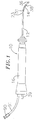
- catheter 10 comprises an elongated catheter body 12 having proximal and distal ends, a tip section 14 at the distal end of the catheter body 12 , and a control handle 16 at the proximal end of the catheter body 12 .
- the catheter body 12 comprises an elongated tubular construction having a single, axial or central lumen 18 .
- the catheter body 12 is flexible, i.e., bendable, but substantially non-compressible along its length.
- the catheter body 12 can be of any suitable construction and made of any suitable material.
- a presently preferred construction comprises an outer wall 22 made of a polyurethane, or PEBAX.
- the outer wall 22 comprises an imbedded braided mesh of stainless steel or the like to increase torsional stiffness of the catheter body 12 so that, when the control handle 16 is rotated, the tip section 14 of the catheter 10 will rotate in a corresponding manner.
- Extending through the single lumen 18 of the catheter body 12 are lead wires, an infusion tube, and a compression coil through which a puller wire extends.
- a single lumen catheter body is preferred over a multi-lumen body because it has been found that the single lumen body permits better tip control when rotating the catheter.
- the single lumen permits the lead wires, infusion tube, and the puller wire surrounded by the compression coil to float freely within the catheter body. If such wires and tube were restricted within multiple lumens, they tend to build up energy when the handle is rotated, resulting in the catheter body having a tendency to rotate back if, for example, the handle is released, or if bent around a curve, to flip over, either of which are undesirable performance characteristics.
- the outer diameter of the catheter body 12 is not critical, but is preferably no more than about 2.67 mm (8 french), more preferably 2.33 mm (7 french).
- the thickness of the outer wall 22 is not critical, but is thin enough so that the central lumen 18 can accommodate an infusion tube, a puller wire, lead wires, and any other wires, cables or tubes.
- the inner surface of the outer wall 22 is lined with a stiffening tube 20 , which can be made of any suitable material, such as polyimide or nylon.
- the stiffening tube 20 along with the braided outer wall 22 , provides improved torsional stability while at the same time minimizing the wall thickness of the catheter, thus maximizing the diameter of the central lumen 18 .
- the outer diameter of the stiffening tube 20 is about the same as or slightly smaller than the inner diameter of the outer wall 22 .
- Polyimide tubing is presently preferred for the stiffening tube 20 because it may be very thin walled while still providing very good stiffness. This maximizes the diameter of the central lumen 18 without sacrificing strength and stiffness.
- a particularly preferred catheter has an outer wall 22 with an outer diameter of from about 2.29 mm (0.090 inch) to about 2.39 mm (0.094 inch) and an inner diameter of from about 1.55 mm (0.061 inch) to about 1.65 mm (0.065 inch) and a polyimide stiffening tube 20 having an outer diameter of from about 1.52 mm (0.060 inch) to about 1.63 mm (0.064 inch) and an inner diameter of from about 1.30 mm (0.051 inch) to about 1.42 mm (0.056 inch).
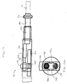
- the tip section 14 comprises a short section of tubing 19 having three lumens.
- the tubing 19 is made of a suitable non-toxic material that is preferably more flexible than the catheter body 12 .
- a presently preferred material for the tubing 19 is braided polyurethane, i.e., polyurethane with an embedded mesh of braided stainless steel or the like.
- the outer diameter of the tip section 14 like that of the catheter body 12 , is preferably no greater than about 2.67 mm (8 french), more preferably 2.33 mm (7 french). The size of the lumens is not critical.
- the tip section 14 has an outer diameter of about 2.33 mm (7 french (.092 inch)) and the first lumen 30 and second lumen 32 are generally about the same size, each having a diameter of from about 0.51 mm (0.020 inch) to about 0.61 mm (0.024 inch), preferably 0.56 mm (0.022 inch), with the third lumen 34 having a slightly larger diameter of from about 0.81 mm (0.032 inch) to about 0.97 mm (0.038 inch), preferably 0.91 mm (0.036 inch).
- FIG. 2 A preferred means for attaching the catheter body 12 to the tip section 14 is illustrated in FIG. 2.
- the proximal end of the tip section 14 comprises an outer circumferential notch 24 that receives the inner surface of the outer wall 22 of the catheter body 12 .
- the tip section 14 and catheter body 12 are attached by glue or the like.
- the stiffening tube 20 is inserted into the catheter body 12 .
- the distal end of the stiffening tube 20 is fixedly attached near the distal end of the catheter body 12 by forming a glue joint 23 with polyurethane glue or the like.
- a small distance e.g., about 3 mm, is provided between the distal end of the catheter body 12 and the distal end of the stiffening tube 20 to permit room for the catheter body 12 to receive the notch 24 of the tip section 14 .
- a force is applied to the proximal end of the stiffening tube 20 , and, while the stiffening tube 20 is under compression, a first glue joint (not shown) is made between the stiffening tube 20 and the outer wall 22 by a fast drying glue, e.g. Super Glue®. Thereafter a second glue joint 26 is formed between the proximal ends of the stiffening tube 20 and outer wall 22 using a slower drying but stronger glue, e.g., polyurethane.
- a fast drying glue e.g. Super Glue®
- a spacer can be located within the catheter body between the distal end of the stiffening tube and the proximal end of the tip section.
- the spacer provides a transition in flexibility at the junction of the catheter body and tip section, which allows this junction to bend smoothly without folding or kinking.
- a catheter having such a spacer is described in U.S. Patent Application Serial No. 08/924,616, entitled "Steerable Direct Myocardial Revascularization Catheter".
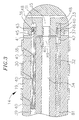
- the tip electrode 36 At the distal end of the tip section 14 is a tip electrode 36 .
- the tip electrode 36 has a diameter about the same as the outer diameter of the tubing 19 .
- the tip electrode 36 is generally solid, having a fluid passage 35 and a pair of blind holes 31 and 33 that correspond in size and location to the three lumens 34 , 30 and 32 respectively in the tip section 14 .
- the blind holes 31 and 33 extend from the proximal end of the tip electrode 36 , but do not extend through to the distal end of the tip electrode.
- the fluid passage 35 comprises an axial branch and six transverse branches 48 that extend radially from the distal end of the axial branch to the outer surface of the tip electrode 36 . It is understood that the configuration of the fluid passage may vary as desired.
- a preferred tip electrode has an effective length, i.e., from its distal end to the distal end of the tubing, of about 3.5 mm, and an actual length, i.e., from its distal end to its proximal end, of about 4.0 mm.
- this preferred tip electrode 36 is attached to the tubing 19 by creating a notch 37 in the proximal end of the tip electrode 36 , placing the proximal end of the tip electrode on the distal end of the tubing 19 , and filling the notch 37 with glue.
- the wires and tubes that extend into the tip electrode 36 help to keep the tip electrode in place on the tip section.
- each ring electrode 38 there are three ring electrodes 38 mounted on the tubing 19 proximal to the tip electrode 36 . It is understood that the presence and number of ring electrodes 38 may vary as desired. Each ring electrode 38 is slid over the tubing 19 and fixed in place by glue or the like.
- the tip electrode 36 and ring electrodes 38 can be made of any suitable material, and are preferably machined from platinum-iridium bar (90% platinum/10% iridium).
- the tip electrode 36 and ring electrodes 38 are each connected to a separate lead wire 40 .
- the lead wires 40 extend through the first lumen 30 of tip section 14 , the central lumen 18 of the catheter body 12 , and the control handle 16 , and terminate at their proximal end in an input jack (not shown) that may be plugged into an appropriate monitor (not shown).
- the portion of the lead wires 40 extending through the central lumen 18 of the catheter body 12 , control handle 16 and proximal end of the tip section 14 are enclosed within a protective sheath 39 , which can be made of any suitable material, preferably polyimide.
- the protective sheath 39 is anchored at its distal end to the proximal end of the tip section 14 by gluing it in the second lumen 32 with polyurethane glue or the like.
- the lead wires 40 are attached to the tip electrode 36 and ring electrodes 38 by any conventional technique. Connection of a lead wire 40 to the tip electrode 36 is accomplished, for example, by welding the lead wire 40 into the second hole 33 in the tip electrode.
- Connection of a lead wire 40 to a ring electrode 38 is preferably accomplished by first making a small hole through the tubing 19 .
- a hole can be created, for example, by inserting a needle through the tubing 19 and heating the needle sufficiently to form a permanent hole.
- a lead wire 40 is then drawn through the hole by using a microhook or the like.
- the ends of the lead wire 40 are then stripped of any coating and soldered or welded to the underside of the ring electrode 38 , which is then slid into position over the hole and fixed in place with polyurethane glue or the like.
- a temperature sensing means is provided for the tip electrode 36 and, if desired, the ring electrodes 38 . Any conventional temperature sensing means, e.g., a thermocouple or thermistor, may be used.
- a preferred temperature sensing means for the tip electrode 36 comprises a thermocouple formed by a wire pair.
- One wire of the wire pair is a copper wire 41 , e.g., a number 40 copper wire.
- the other wire of the wire pair is a constantan wire 45 , which gives support and strength to the wire pair.
- the wires 41 and 45 of the wire pair are electrically isolated from each other except at their distal ends where they contact and are twisted together, covered with a short piece of plastic tubing 43 , e.g., polyimide, and covered with epoxy.
- the plastic tubing 43 is then attached in the first blind hole 31 of the tip electrode 36 , by polyurethane glue or the like.
- the wires 41 and 45 extend through the first lumen 30 in the tip section 14. Within the catheter body 12 the wires 41 and 45 extend through the protective sheath 39 with the lead wires 40 .
- the wires 41 and 45 then extend out through the control handle 16 and to a connector (not shown) connectable to a temperature monitor (not shown).
- the temperature sensing means may be a thermistor.
- a suitable thermistor for use in the present invention is Model No. AB6N2-GC14KA143E/37C sold by Thermometrics (New Jersey).
- a puller wire 42 extends through the catheter body 12 , is anchored at its proximal end to the control handle 16 , and is anchored at its distal end to the tip section 14 .
- the puller wire 42 is made of any suitable metal, such as stainless steel or Nitinol, and is preferably coated with Teflon® or the like. The coating imparts lubricity to the puller wire 42 .
- the puller wire 42 preferably has a diameter ranging from about 0.15 mm (0.006 inches to about 0.25 mm (0.010 inches).
- a compression coil 44 is situated within the catheter body 12 in surrounding relation to the puller wire 42 .
- the compression coil 44 extends from the proximal end of the catheter body 12 to the proximal end of the tip section 14 .
- the compression coil 44 is made of any suitable metal, preferably stainless steel.
- the compression coil 44 is tightly wound on itself to provide flexibility, i.e., bending, but to resist compression.
- the inner diameter of the compression coil 44 is preferably slightly larger than the diameter of the puller wire 42 .
- the Teflon® coating on the puller wire 42 allows it to slide freely within the compression coil 44 .
- the outer surface of the compression coil 44 can be covered by a flexible, non-conductive sheath, e.g., made of polyimide tubing, to prevent contact between the compression coil 44 and any other wires within the catheter body 12 .
- the compression coil 44 is anchored at its proximal end to the proximal end of the stiffening tube 20 in the catheter body 12 by glue joint 50 and at its distal end to the tip section 14 by glue joint 51 .
- Both glue joints 50 and 51 preferably comprise polyurethane glue or the like.
- the glue may be applied by means of a syringe or the like through a hole made between the outer surface of the catheter body 12 and the central lumen 18 . Such a hole may be formed, for example, by a needle or the like that punctures the outer wall 22 of the catheter body 12 and the stiffening tube 20 which is heated sufficiently to form a permanent hole.
- the glue is then introduced through the hole to the outer surface of the compression coil 44 and wicks around the outer circumference to form a glue joint about the entire circumference of the compression coil 44 .
- the puller wire 42 extends into the second lumen 32 of the tip section 14 .
- the puller wire 42 is anchored at its distal end to the tip electrode 36 within the second blind hole 33 .
- a preferred method for anchoring the puller wire 42 within the tip electrode 36 is by crimping metal tubing 46 to the distal end of the puller wire 42 and soldering the metal tubing 46 inside the second blind hole 33 .
- Anchoring the puller wire 42 within the tip electrode 36 provides additional support, reducing the likelihood that the tip electrode 36 will fall off the tip section 14 .
- the puller wire 42 can be attached to the side of the tip section 14 .
- the puller wire 42 extends through a plastic, preferably Teflon®, sheath 81 , which prevents the puller wire 42 from cutting into the wall of the tip section 14 when the tip section is deflected.
- An infusion tube is provided within the catheter body 12 for infusing fluids, e.g., saline, to cool the tip electrode 36 .
- the infusion tube may also be used to infuse drugs or to collect tissue or fluid samples.
- the infusion tube may be made of any suitable material, and is preferably made of polyimide tubing.
- a preferred infusion tube has an outer diameter of from about 0.81 mm (0.032 inch) to about 0.91 mm (0.036 inch) and an inner diameter of from about 0.71 mm (0.028 inch) to about 0.81 mm (0.032 inch).
- a first infusion tube segment 88 extends through the central lumen 18 of the catheter body 12 and terminates in the proximal end of the third lumen 34 of the tip section 14 .
- the distal end of the first infusion tube segment 88 is anchored in the third lumen 34 by polyurethane glue or the like.
- the proximal end of the first infusion tube segment 88 extends through the control handle 16 and terminates in a luer hub 90 or the like at a location proximal to the control handle.
- a second infusion tube segment 89 is provided at the distal end of the third lumen 34 and extends into the fluid passage 35 of the tip electrode 36 .
- the second infusion tube segment 89 is anchored within the third lumen 34 and the fluid passage 35 by polyurethane glue or the like.
- the second infusion tube segment 89 like the puller wire 42 , provides additional support for the tip electrode.
- fluid may be injected into the first infusion tube segment 88 through the luer hub 90 , and flows through the first infusion tube segment 88 , through the third lumen 34 , through the second infusion tube segment, into 89 into the fluid passage 35 in the tip electrode 36 , and out the transverse branches 48 of the fluid passage 35 in the tip electrode.
- the fluid passage may have other configurations as desired.
- the fluid passage 35 may form a longitudinal hole that extends out the distal end of the tip electrode 36 , as shown in FIG. 3A, or the tip electrode 36 may be porous enough to allow fluids to pass to the outer surface of the tip electrode, the interconnecting pores forming the fluid passage.
- a single lumen side arm 94 is fluidly connected to the central lumen 18 near the proximal end of the catheter body 12 .
- the first infusion tube segment 88 extends through the catheter body 12 and out the side arm 94 , where it terminates in a luer hub 90 or the like.
- the side arm 94 is preferably made of the same material as the outer wall 22 , but preferably has a greater thickness, e.g., 1.40 mm (0.055 inch). Where the side arm 94 meets the catheter body 12 , a molded joint can be provided to provide additional strength and support.
- the molded joint can be made of any suitable biocompatable material, and is preferably made of polyurethane.
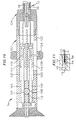
- the distal end of the control handle 16 comprises a piston 54 with a thumb control 56 for manipulating the puller wire 42 .
- the proximal end of the catheter body 12 is connected to the piston 54 by means of a shrink sleeve 28 .
- the puller wire 42 , lead wires 40 , thermocouple wires 41 and 45 , and first infusion tube segment 88 extend through the piston 54 .
- the puller wire 42 is anchored to an anchor pin 57 , located proximal to the piston 54 .
- the lead wires 40 and thermocouple wires 41 and 45 are within the protective sheath 39 .
- the first infusion tube segment 88 extends into another protective sheath 91 , preferably made of polyurethane, similar to the side arm 94 , described above.
- the protective sheathes 39 and 91 are anchored to the piston 54 , preferably by polyurethane glue or the like at a glue joint 53 , allowing the first infusion tube segment 88 , lead wires 40 and thermocouple wires 41 and 45 longitudinal movement within the control handle 16 so that they does not break when the piston 54 is adjusted to manipulate the puller wire 42 .
- the puller wire 42 extends through a transfer tube 27 , preferably a polyimide tube, to allow longitudinal movement of the puller wire near the glue joint 53 .
- the piston 54 lies within the barrel 55 of the control handle.
- the barrel 55 is generally solid having a piston chamber for receiving the piston 54 .
- Extending proximally from the piston chamber are three longitudinal holes 58 , 59 and 60 and a transverse hole for receiving the anchor pin 57 .
- the second longitudinal hole 59 is in communication with the transverse hole.
- the first infusion tube segment 88 within the protective sheath 91 extends through the first longitudinal hole 58 while the lead wires 40 .
- the puller wire 42 extends through the second longitudinal hole 59 and is anchored to the anchor pin 57 in the transverse hole.
- the thermocouple wires 41 and 45 within the protective sheath 39 extend through the third longitudinal hole 60 .
- chamber 62 provides additional space to avoid undesirable bending of the first infusion tube segment 88 .
- the space has a length of at least 0.50 inch and more preferably about from about 1.52 mm (0.60 inch) to about 2.29 mm (0.90 inch).
- an electromagnetic sensor 72 is located within the distal end of the tip section 14 .
- the tip electrode 36 is connected to the tubing 19 of the tip section 14 by means of a plastic housing 21 , preferably made of polyetheretherketone (PEEK).
- PEEK polyetheretherketone
- the proximal end of the tip electrode 36 is notched circumferentially to form a stem 70 , which fits inside the distal end of the plastic housing 21 and is bonded to the housing 21 by polyurethane glue or the like.
- the proximal end of the plastic housing 21 is bonded with polyurethane glue or the like to the distal end of the tubing 19 of the tip section 14 .
- the plastic housing is about 1 cm long.
- the tip electrode 36 has a total length of about 7 mm, with the stem 70 having a length of about 3.5 mm (i.e., half the total length of the tip electrode).
- the distal end of the tip electrode 36 is generally solid with a blind hole 31 and a fluid passage 33 with six transverse branches 48 .
- the stem 70 of the tip electrode 36 is generally hollow.
- a second infusion tube segment 89 extends into and is anchored in the fluid passage 33 of the tip electrode 36 .
- the infusion tube segments 88 and 89 preferably have an outer diameter of about from 0.74 mm (0.029 inch) to about 0.84 mm (0.033 inch) and an inner diameter of from about 0.64 mm (0.025 inch) to about 0.74 mm (0.029 inch).
- a puller wire 42 extends into and is anchored in the blind hole 31 of the tip electrode 36 .
- a pair of thermocouple wires 41 and 45 also extend into and are soldered into the first hole 31 of the tip electrode 36 , and the copper wire 41 acts also as a lead wire 40 for the tip electrode.
- the electromagnetic sensor 72 is positioned within the plastic housing 21 and hollow stem 70 of the tip electrode 36 . The sensor 72 is fixedly attached within the tip electrode 36 and the plastic housing 21 by polyurethane glue or the like.
- ring electrodes 38 Mounted on the plastic housing 21 are three ring electrodes 38 .
- the presence and number of ring electrodes 38 can vary as desired.
- Each ring electrode 38 is slid over the plastic housing 21 and fixed in place by glue or the like.
- one or more ring electrodes 38 can be positioned over the flexible tubing 19 of the tip section 14 .
- Lead wires are attached to the ring electrodes 38 generally as described above. However, due to the length of the plastic housing 21 , the most distal ring electrode 38 is mounted on the plastic housing 21 at a position above the stem 70 of the tip electrode 36 . As a result, the lead wire 40 for the most distal ring electrode 38 extends though a hole 49 in the plastic housing 21 that is proximal to the distal ring electrode 38 and stem 70 . The lead wire 40 extends a short distance along the outside of the plastic housing 21 and is soldered to the underside of the most distal ring electrode 38 . Polyurethane glue or the like is used to cover the exposed section of the lead wire 40 and to fill in the hole 49 .
- the electromagnetic sensor 72 is connected to a electromagnetic sensor cable 74 , which extends through the third lumen 34 of the tip section 14 , through the central lumen 18 of the catheter body 12 , and into the control handle 16 .
- the electromagnetic sensor cable 74 then extends out the proximal end of the control handle 16 within an umbilical cord 78 to a sensor control module 75 that houses a circuit board (not shown).
- the circuit board can be housed within the control handle 16 , for example, as described in U.S. Patent Application Serial No. 08/924,616, entitled "Steerable Direct Myocardial Revascularization Catheter".
- the electromagnetic sensor cable 74 comprises multiple wires encased within a plastic covered sheath.
- the wires of the electromagnetic sensor cable 74 are connected to the circuit board.
- the circuit board amplifies the signal received from the electromagnetic sensor 72 and transmits it to a computer in a form understandable by the computer by means of the sensor connector 77 at the proximal end of the sensor control module 75 , as shown in FIG. 8.
- the circuit board preferably contains an EPROM chip which shuts down the circuit board approximately 24 hours after the catheter has been used. This prevents the catheter, or at least the electromagnetic sensor, from being used twice. Suitable electromagnetic sensor for use with the present invention are described, for example, in U.S. Patent Nos.
- a preferred electromagnetic mapping sensor 72 has a length of from about 6 mm to about 7 mm and a diameter of about 1.3 mm.
- the patient is placed in a magnetic field generated, for example, by situating under the patient a pad containing coils for generating a magnetic field.
- a reference electromagnetic sensor is fixed relative to the patient, e.g., taped to the patient's back, and the catheter containing a second electromagnetic sensor is advanced into the patient's heart.
- Each sensor comprises three small coils that in the magnetic field generate weak electrical signals indicative of their position in the magnetic field.
- Signals generated by both the fixed reference sensor and the second sensor in the heart are amplified and transmitted to a computer that analyzes the signals and then displays the signals on a monitor.
- the sensor can also detect displacement of the catheter that is caused by contraction of the heart muscle.
- a preferred mapping system includes a catheter comprising multiple electrodes and an electromagnetic sensor.
- the catheter body 12 is generally similar to that described above, having an open central lumen 18 .
- the catheter body 12 in this embodiment does not comprise a stiffening tube 20 , however, because additional space is needed within the central lumen 10 to include the electromagnetic sensor cable sensor cable 74 .
- the catheter body has an outer diameter no greater than about 2.67 mm (8 French), more preferably about 2.33 mm (7 French to about 2.50 mm (7.5 French)
- the control handle 16 is also generally similar to that described above. However, the electromagnetic sensor cable 74 extends out the proximal end of the control handle 16 where it is connected to the sensor control module 75 .
- An alternative embodiment of a catheter according to the present invention is a bidirectional catheter containing two puller wires to enhance the ability to manipulate the tip section.
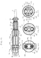
- the tip section 14 of this embodiment contains four lumens.
- the diameters of the first lumen 30 and second lumen 32 are similar in size, and are each preferably 0.46 mm (0.018 inch).
- the diameters of the third lumen 34 and fourth lumen 35 are also similar in size and are each preferably 0.74 mm (0.029 inch)
- the tip section 14 carries a tip electrode 36 and ring electrodes 38 .
- a thermocouple, or other temperature sensing means, is provided for the tip electrode 36 as discussed above.
- the tip section 14 also contains an electromagnetic sensor 72 , and the electromagnetic sensor cable 74 also extends through the third lumen 34 .
- a first infusion tube segment 88 extends through the control handle 16 and catheter body 12 and into the fourth lumen 35 .
- a second infusion tube segment 89 extends from the distal end of the fourth lumen 35 in the tip section 14 and into the tip electrode 36 in a manner similar to the embodiment described above.
- Two puller wires 34 and surrounding compression coils 44 extend from the control handle 16 through the central lumen 18 of the catheter body 12 as described above. Within the tip section 14 , one puller wire 34 extends into the first lumen 30 and the other puller wire extends into the second lumen 32 . The puller wires 34 then extend into holes in the tip electrode 36 preferably coaxial with the first lumen 30 and second lumen 32 and are anchored within the holes of the tip electrode as described above.
- the puller wires 34 each extend through a plastic, preferably Teflon®, sheath 81 , to prevent the puller wires 42 from cutting into the wall of the tip section 14 when the tip section is deflected
- the lumens 30 and 32 of the tip section receiving the puller wires may be in adjacent quadrants, but are preferably in opposing quadrants.
- the distal ends of one or both of the puller wires may be anchored to the side wall of the catheter tip section for example as described in U.S. Patent Application Serial No. 08/924,611, reference.
- the first puller wire may be anchored proximal to the anchor location of the second puller wire.
- a particularly preferred catheter construction comprising multiple puller wires including control handle construction is disclosed in U.S. Patent Application Serial No. 08/924,611, entitled “Omni-Directional Steerable Catheter”.
- Such application describes a suitable control handle for manipulating two or more puller wires.
- the described control handle includes a central passage that may be expanded to accommodate the electrode lead wires, electromagnetic sensor cable, optic fiber and even infusion tube. Further, an extension of the handle may be provided to house the circuit board for the electromagnetic sensor, e.g., in the same manner as shown in FIG. 8 .
- FIG. 10 An alternative control handle 16 particularly suitable for the bidirectional catheter embodiment of the invention is illustrated in FIG. 10 .
- the control handle 16 comprises a generally solid and generally cylindrical housing 102 having a nose piece 104 at its distal end.
- the housing 102 and nose piece 104 can be made of any suitable material, preferably acetal.
- the catheter body 12 is fixedly attached to the nose piece 104 by means of a shrink sleeve, as described above.
- each rack gear channel 105 is located in opposite quadrants within the housing 102 .
- a rack gear 106 is Slidably mounted within each rack gear channel 105 .
- Each rack gear 106 is generally rectangular having teeth 108 along the length of its interior edge.
- a spur gear 110 is between the rack gears 106 , also having teeth 112 .
- the teeth 112 of the spur gear 110 receive the teeth 108 of the rack gears 106 such that proximal movement off one rack gear results in distal movement of the other rack gear.
- each puller wire 42 is attached to the distal end of one of the rack gears 106 by a puller wire coupling 114 .
- the coupling 114 may be integral with the rack gear 106 or fixedly attached to it.
- Each rack gear 106 may be soldered or glued to the coupling 114 , for example, with polyurethane or epoxy.
- the proximal end of each puller wire coupling 114 may comprise a threaded hole to receive a threaded post at the distal end of the corresponding rack gear 106 .
- the couplings 114 can be made of any suitable material, preferably aluminum.
- each coupling 114 contains a threaded axial hole 115 that receives a threaded set screw 116 .
- the set screw 116 has an axial bore 118 therethrough for passage of the proximal end of the puller wire 42 .
- the axial bore 118 has a distal section with a diameter slightly larger than the diameter of the puller wire 42 and a proximal section having a diameter larger than that of the distal section.
- the axial bore 118 extends through the proximal end of the set screw 116 .
- the puller wire 42 extends through the axial bore 118 of the set screw 116 and is anchored thereto.
- a preferred means for anchoring the puller wire 42 to the set screw 116 comprises a short piece of hypodermic stock 120 that is fixedly attached, i.e., by crimping, to the proximal end of the puller wire 42 after it has passed through the distal section of the axial bore 118 of the set screw 116 .
- the hypodermic stock 120 has a diameter greater than the diameter of the distal section of the axial bore 118 and prevents the puller wire 42 from being pulled through the set screw 116 .
- a cross-member e.g., stainless steel ribbon, may be welded to the proximal end of the puller wire 42 such that the cross-member prevents the puller wire from being pulled through the axial bore 118 of the set screw 116 . It is understood that any mechanism for attaching the proximal end of the puller wire to the coupling 114 may be used.
- an axial hole 119 which has a diameter similar to the distal end of the axial bore 118 in the set screw 116 .
- the distal end of the axial hole 119 is in communication with the proximal end of the axial bore 118 to provide a passage into which the puller wire 42 can extend when the corresponding rack gear 106 and coupling 114 are moved distally. This prevents the puller wire 42 from buckling.
- the handle housing 102 contains a slot 122 along one side, corresponding with the position of one of the rack gears 106 .
- a set screw 124 extends through the slot 122 into the rack gear 106 through the puller wire coupling 114 .
- a deflection knob 126 is placed on the outside end of the set screw 124 for easy manipulation of the control handle 16 .
- the deflection knob 126 extends around the circumference of the handle housing 102 , allowing the user to manipulate the knob 126 no matter how the handle is turned.
- the set screw 124 is positioned on the rack gear 106 so that when both rack gears 106 are in a neutral position, i.e., in line with each other, the deflection knob 126 is situated approximately at the midsection of the slot 122 .
- the corresponding rack gear 106 moves in a proximal direction.
- the attached puller wire 42 also is pulled proximally, causing the tip section 14 to deflect in the direction of the quadrant of the lumen in the tip section 14 through which that puller wire extends.
- the corresponding rack gear 106 moves distally.
- the opposite rack gear 106 moves proximally, pulling the corresponding puller wire 42 and deflecting the tip section 14 in the opposite direction.
- Passages are provided within the handle housing 102 for the infusion tube 88 , lead wires 40 , thermocouple wires 41 and 45 and sensor cable 74 to extend through the housing 102 and out the distal end.
- the infusion tube 88 , lead wires 40 , thermocouple wires 41 and 45 and sensor cable 74 extend out the proximal end of the handle housing 102 and attached to a luer hub or to appropriate monitors, as described above.
- the control handle 16 comprises a generally tubular handle housing 102 , which can be made of any suitable rigid material.
- the housing 102 comprises three piston chambers, an axial distal piston chamber 131 and two smaller proximal piston chambers 135 .
- the proximal piston chambers 135 are preferably in opposite quadrants of the housing and overlap the distal piston chamber 131 .
- Mounted within the distal piston chamber 131 and extending out of the distal end of the housing 102 is a slidable distal piston 130 having a thumb rest 132 at its distal end and an axial passage 133 .
- the proximal end of the catheter body 12 is attached, e.g., by glue, to the distal piston 130 .
- the protective sheath 39 containing the puller wires 42 , lead wires 40 , thermocouple wires 41 and 45 , and the first infusion tube 88 extend through the axial passage 133 of the distal piston 130 .
- two slidable proximal pistons 134 are located in the proximal piston chambers 135 .
- the proximal pistons 134 can be made of any suitable material. Aluminum is presently preferred.
- Each puller wire 42 is anchored at its proximal end to the distal end of a proximal piston 134 .
- the puller wires 42 can be fixedly attached to the proximal pistons 134 by any suitable means, for example, by means of a coupling as described above.
- distal movement of the distal piston 130 relative to the handle housing 102 by pushing on the thumb rest 132 also results in distal movement of the catheter body 12 , the puller wires 42 and the proximal pistons 134 to which the puller wires are attached. Tip deflection does not occur however when both puller wires are moved simultaneously. Accordingly, means are provided for preventing simultaneous movement of the puller wires.
- the means for preventing simultaneous movement of the puller wires 42 comprises means for anchoring, i.e., preventing movement of, one, but not both, of the proximal pistons 134 . This is done by the combination of a circumferential notch 140 along the length of each proximal piston 134 and a means for engaging the circumferential notch 140 of a selected one of the proximal pistons 134 .
- a preferred engaging means comprises a movable bar 142 which extends diametrically through the handle housing 102 and extends slightly out of the housing on each side to thereby create what appears to be a button on each side of the housing at a position corresponding to the circumferential notches 104 of the proximal pistons 134 as shown in FIGs. 12 and 12A.
- the bar 142 comprises a generally oval slot 146 . Both of the proximal pistons 134 extend through the slot 146 .
- the slot 146 has a width slightly greater than the diameter of the proximal pistons 134 .
- the height of the bar 142 is less than the length of the circumferential notches 140 so that the bar 142 can be received by and engages the notches 140 .
- the length of the slot 146 is selected to allow lengthwise movement of only one proximal piston 134 at a time. That is, as shown in FIG. 13, the bar 142 has been moved in a first direction until the end of the slot 146 engages the circumferential notch of one proximal piston 134 . In this arrangement, the engaged proximal piston is prevented from moving longitudinally by the bar 142 , but the other proximal piston can move freely through the slot 146 . If the bar 142 is moved in the other direction the previously engaged proximal piston will be afforded free longitudinal movement and the previously freely moving proximal piston will be engaged.
- a proximal piston 134 When a proximal piston 134 is engaged by the bar 142 , it acts as a fixed anchor for the puller wire 42 attached to it. Hence when the distal piston 130 is moved distally relative to the housing 102 by pushing the thumb rest 132 , the catheter body 12 will move distally relative to the anchored puller wire 42 . This results in deflection of the tip section 14 in the direction of the tip lumen carrying that puller wire. When the opposite proximal piston is engaged, deflection of the tip in the opposite direction will occur.
Landscapes
- Health & Medical Sciences (AREA)
- Life Sciences & Earth Sciences (AREA)
- Engineering & Computer Science (AREA)
- Veterinary Medicine (AREA)
- Animal Behavior & Ethology (AREA)
- Public Health (AREA)
- Biomedical Technology (AREA)
- Heart & Thoracic Surgery (AREA)
- General Health & Medical Sciences (AREA)
- Surgery (AREA)
- Hematology (AREA)
- Anesthesiology (AREA)
- Biophysics (AREA)
- Pulmonology (AREA)
- Otolaryngology (AREA)
- Physics & Mathematics (AREA)
- Plasma & Fusion (AREA)
- Nuclear Medicine, Radiotherapy & Molecular Imaging (AREA)
- Cardiology (AREA)
- Mechanical Engineering (AREA)
- Medical Informatics (AREA)
- Molecular Biology (AREA)
- Media Introduction/Drainage Providing Device (AREA)
- Surgical Instruments (AREA)
- Magnetic Resonance Imaging Apparatus (AREA)
- Measurement And Recording Of Electrical Phenomena And Electrical Characteristics Of The Living Body (AREA)
Claims (18)
- Cathéter avec embout irrigué orientable (10) comprenant :un corps de cathéter (12) ayant une paroi externe (22), des extrémités proximale et distale, et une lumière (18) s'étendant à travers ;une poignée de commande (16) à l'extrémité proximale du corps de cathéter (12) ;une section d'embout (14) comprenant un segment de tube souple (19) ayant des extrémités proximale et distale et au moins une lumière (30 ; 32 ; 34) passant à travers, l'extrémité proximale de la section d'embout (14) étant attachée fixement à l'extrémité distale du corps de cathéter (12) ;une électrode d'embout (36) attachée fixement à l'extrémité distale du tube (19) de la section d'embout (14), l'électrode d'embout ayant au moins un passage de fluide (35) en communication de fluide avec une lumière (34) dans la section d'embout' (14) ;un premier segment de tube d'infusion (88) ayant des extrémités proximale et distale, le premier segment de tube d'infusion s'étendant dans la lumière (18) à l'intérieur du corps de cathéter (12) ;un deuxième segment de tube d'infusion (89) ayant une extrémité proximale disposée à l'extrémité distale de la lumière (34) dans la section d'embout (14) dans laquelle le premier segment de tube d'infusion (88) est disposé et une extrémité distale disposée dans le passage de fluide (35) dans l'électrode d'embout (36) ; etun moyen (42) pour dévier la section d'embout (14) en manipulant la poignée de commande (16),caractérisé en ce que:la lumière s'étendant à travers le corps de cathéter (12) et à travers laquelle le premier segment de tube d'infusion s'étend, comprend une lumière centrale unique (18) qui est définie par une surface interne de la paroi externe (22) ;le premier segment de tube d'infusion (88) s'étend à travers la lumière centrale (18) dans le corps de cathéter (12) avec l'extrémité distale disposée à l'extrémité proximale d'une lumière (34) dans la section d'embout (14) ; etle corps de cathéter (12) comprend en outre un tube de renforcement interne (20) recouvrant la surface interne de la paroi externe (22).
- Cathéter selon la revendication , dans lequel le passage de fluide comprend au moins un passage longitudinal (35) s'étendant à travers l'électrode d'embout (36) jusqu'à la surface externe de l'électrode d'embout.
- Cathéter selon la revendication 1 ou 2, dans lequel le passage de fluide (35) comprend au moins un passage transversal (48).
- Cathéter selon la revendication 1, 2 ou 3, dans lequel l'électrode d'embout (36) est poreuse et dans lequel le passage de fluide (35) est formé par des pores d'interconnexion de l'électrode d'embout.
- Cathéter selon l'une quelconque des revendications précédentes, dans lequel l'extrémité proximale du premier segment de tube d'infusion (88) s'étend hors du côté du corps de cathéter (12).
- Cathéter selon l'une quelconque des revendications précédentes, dans lequel la poignée de commande (16) comprend un premier élément (54) attaché fixement à l'extrémité proximale du corps de cathéter (12) et un deuxième élément (55) mobile par rapport au premier élément.
- Cathéter selon la revendication 6, dans lequel le moyen de déviation comprend un fil de traction (42) ayant une extrémité proximale et une extrémité distale, le fil de traction s'étendant depuis la poignée de commande (16), à travers la lumière centrale (18) du corps de cathéter (12) et jusqu'à la lumière (30 ; 32 ; 34) dans la section d'embout (14), dans lequel l'extrémité distale du fil de traction est attachée fixement dans la section d'embout (14) et l'extrémité proximale du fil de traction est attachée fixement au deuxième élément (55) de la poignée de commande, moyennant quoi la manipulation du premier élément (54) de la poignée de commande par rapport au deuxième élément de la poignée de commande déplace le fil de traction (42) par rapport au corps de cathéter (12), entraînant une déviation de la section d'embout (14).
- Cathéter selon l'une quelconque des revendications précédentes, comprenant en outre un capteur électromagnétique (72) dans la partie distale de la section d'embout (14) pour produire des signaux électriques indiquant l'emplacement du capteur de mappage électromagnétique et un moyen (74, 77) pour connecter le capteur électromagnétique à un système d'imagerie.
- Cathéter selon l'une quelconque des revendications précédentes, dans lequel l'extrémité proximale du premier segment de tube d'infusion (88) se termine dans un raccord Luer (90).
- Cathéter selon l'une quelconque des revendications précédentes, dans lequel l'extrémité proximale du premier segment de tube d'infusion (88) s'étend hors de l'extrémité proximale de la poignée de commande (16).
- Cathéter selon l'une quelconque des revendications précédentes, dans lequel la section d'embout (14) a trois lumières (30, 32, 34) s'étendant à travers.
- Cathéter selon l'une quelconque des revendications 7 et l'une quelconque des revendications annexées à cette dernière, dans lequel le moyen de déviation comprend en outre une spirale de compression (44) s'étendant à travers le corps de cathéter (12) dans une position entourant le fil de traction (42).
- Cathéter selon l'une quelconque des revendications précédentes, comprenant en outre un moyen de détection de la température (41, 45).
- Cathéter selon la revendication 13, dans lequel le moyen de détection de la température comprend un thermocouple formé par une paire de fils émaillés comprenant un fil de cuivre (41) et un fil de constantan (45), dans lequel la paire de fils s'étend à travers la lumière (18) dans le corps de cathéter (12) et une lumière (30) dans la section d'embout (14), et est attachée fixement dans un trou borgne (31) dans l'électrode d'embout (36).
- Cathéter selon l'une quelconque des revendications précédentes, dans lequel la paroi externe (22) du corps de cathéter (12) comprend du polyuréthanne ou PEBAX.
- Cathéter selon l'une quelconque des revendications précédentes, dans lequel la paroi externe (22) du corps de cathéter (12) comprend une maille en acier inoxydable tressée intégrée.
- Cathéter selon l'une quelconque des revendications précédentes, dans lequel le tube de renforcement (20) comprend du polyimide.
- Cathéter selon l'une quelconque des revendications précédentes, dans lequel le tube souple (19) de la section d'embout (14) est composé de polyuréthanne.
Applications Claiming Priority (2)
| Application Number | Priority Date | Filing Date | Title |
|---|---|---|---|
| US982113 | 1997-12-01 | ||
| US08/982,113 US6120476A (en) | 1997-12-01 | 1997-12-01 | Irrigated tip catheter |
Publications (2)
| Publication Number | Publication Date |
|---|---|
| EP0928601A1 EP0928601A1 (fr) | 1999-07-14 |
| EP0928601B1 true EP0928601B1 (fr) | 2007-04-25 |
Family
ID=25528853
Family Applications (1)
| Application Number | Title | Priority Date | Filing Date |
|---|---|---|---|
| EP98309803A Expired - Lifetime EP0928601B1 (fr) | 1997-12-01 | 1998-11-30 | Catheter avec embout irrigué |
Country Status (4)
| Country | Link |
|---|---|
| US (2) | US6120476A (fr) |
| EP (1) | EP0928601B1 (fr) |
| JP (2) | JP4209019B2 (fr) |
| DE (1) | DE69837652T2 (fr) |
Cited By (2)
| Publication number | Priority date | Publication date | Assignee | Title |
|---|---|---|---|---|
| US8357152B2 (en) | 2007-10-08 | 2013-01-22 | Biosense Webster (Israel), Ltd. | Catheter with pressure sensing |
| US9101734B2 (en) | 2008-09-09 | 2015-08-11 | Biosense Webster, Inc. | Force-sensing catheter with bonded center strut |
Families Citing this family (420)
| Publication number | Priority date | Publication date | Assignee | Title |
|---|---|---|---|---|
| US6171277B1 (en) * | 1997-12-01 | 2001-01-09 | Cordis Webster, Inc. | Bi-directional control handle for steerable catheter |
| WO1999042036A1 (fr) * | 1998-02-20 | 1999-08-26 | General Surgical Innovations, Inc. | Instruments medicaux reutilisables, pliables, ayant une resistance a la fatigue amelioree |
| US6371963B1 (en) * | 1998-11-17 | 2002-04-16 | Scimed Life Systems, Inc. | Device for controlled endoscopic penetration of injection needle |
| EP1568332B1 (fr) * | 1998-12-18 | 2011-05-04 | Celon AG Medical Instruments | Ensemble-electrode pour un instrument chirurgical de coagulation electrothermique de tissu |
| US7194294B2 (en) | 1999-01-06 | 2007-03-20 | Scimed Life Systems, Inc. | Multi-functional medical catheter and methods of use |
| US6405078B1 (en) * | 1999-01-15 | 2002-06-11 | Biosense Webster, Inc. | Porous irrigated tip electrode catheter |
| US6466818B1 (en) | 1999-01-15 | 2002-10-15 | Biosense Webster, Inc. | Porous irrigated tip electrode catheter |
| US20050228367A1 (en) * | 1999-01-25 | 2005-10-13 | Marwan Abboud | Leak detection system for catheter based medical device |
| US6702811B2 (en) | 1999-04-05 | 2004-03-09 | Medtronic, Inc. | Ablation catheter assembly with radially decreasing helix and method of use |
| US20050010095A1 (en) * | 1999-04-05 | 2005-01-13 | Medtronic, Inc. | Multi-purpose catheter apparatus and method of use |
| US6468260B1 (en) * | 1999-05-07 | 2002-10-22 | Biosense Webster, Inc. | Single gear drive bidirectional control handle for steerable catheter |
| US7004936B2 (en) * | 2000-08-09 | 2006-02-28 | Cryocor, Inc. | Refrigeration source for a cryoablation catheter |
| US6471694B1 (en) | 2000-08-09 | 2002-10-29 | Cryogen, Inc. | Control system for cryosurgery |
| US6852120B1 (en) * | 1999-08-10 | 2005-02-08 | Biosense Webster, Inc | Irrigation probe for ablation during open heart surgery |
| AU2751301A (en) * | 1999-11-05 | 2001-05-30 | Zynergy Cardiovascular, Inc. | Catheter assembly having integral electrical connector disposed therein |
| US7570982B2 (en) * | 2000-01-27 | 2009-08-04 | Biosense Webster, Inc. | Catheter having mapping assembly |
| US6628976B1 (en) | 2000-01-27 | 2003-09-30 | Biosense Webster, Inc. | Catheter having mapping assembly |
| US6711428B2 (en) * | 2000-01-27 | 2004-03-23 | Biosense Webster, Inc. | Catheter having mapping assembly |
| US6795721B2 (en) | 2000-01-27 | 2004-09-21 | Biosense Webster, Inc. | Bidirectional catheter having mapping assembly |
| US6458123B1 (en) * | 2000-04-27 | 2002-10-01 | Biosense Webster, Inc. | Ablation catheter with positional sensor |
| US6475214B1 (en) | 2000-05-01 | 2002-11-05 | Biosense Webster, Inc. | Catheter with enhanced ablation electrode |
| US6508802B1 (en) * | 2000-05-23 | 2003-01-21 | Cornell Research Foundation, Inc. | Remote sensing gene therapy delivery device and method of administering a therapeutic solution to a heart |
| US6569160B1 (en) * | 2000-07-07 | 2003-05-27 | Biosense, Inc. | System and method for detecting electrode-tissue contact |
| US6408199B1 (en) | 2000-07-07 | 2002-06-18 | Biosense, Inc. | Bipolar mapping of intracardiac potentials with electrode having blood permeable covering |
| US6546270B1 (en) * | 2000-07-07 | 2003-04-08 | Biosense, Inc. | Multi-electrode catheter, system and method |
| US6669692B1 (en) | 2000-08-21 | 2003-12-30 | Biosense Webster, Inc. | Ablation catheter with cooled linear electrode |
| US6533779B2 (en) | 2001-01-16 | 2003-03-18 | Scimed Life Systems, Inc. | PMR catheter and associated methods |
| US6544220B2 (en) | 2001-02-14 | 2003-04-08 | Scimed Life Systems, Inc. | Fluid jet PMR |
| US20030208252A1 (en) * | 2001-05-14 | 2003-11-06 | O' Boyle Gary S. | Mri ablation catheter |
| EP1429649A4 (fr) * | 2001-09-24 | 2008-08-20 | Best Vascular Inc | Methodes et dispositif utilisant un rayonnement ionisant pour le traitement de l'arythmie cardiaque |
| US7285116B2 (en) | 2004-05-15 | 2007-10-23 | Irvine Biomedical Inc. | Non-contact tissue ablation device and methods thereof |
| US8974446B2 (en) * | 2001-10-11 | 2015-03-10 | St. Jude Medical, Inc. | Ultrasound ablation apparatus with discrete staggered ablation zones |
| US8774913B2 (en) | 2002-04-08 | 2014-07-08 | Medtronic Ardian Luxembourg S.A.R.L. | Methods and apparatus for intravasculary-induced neuromodulation |
| US7653438B2 (en) | 2002-04-08 | 2010-01-26 | Ardian, Inc. | Methods and apparatus for renal neuromodulation |
| US7588568B2 (en) | 2002-07-19 | 2009-09-15 | Biosense Webster, Inc. | Atrial ablation catheter and method for treating atrial fibrillation |
| US7560269B2 (en) * | 2002-12-20 | 2009-07-14 | Acea Biosciences, Inc. | Real time electronic cell sensing system and applications for cytotoxicity profiling and compound assays |
| US6866662B2 (en) | 2002-07-23 | 2005-03-15 | Biosense Webster, Inc. | Ablation catheter having stabilizing array |
| ATE506891T1 (de) | 2002-08-24 | 2011-05-15 | St Jude Medical Atrial Fibrill | Verfahren und gerät zur lokalisierung der fossa ovalis und durchführung einer transseptalen punktion |
| US6984232B2 (en) * | 2003-01-17 | 2006-01-10 | St. Jude Medical, Daig Division, Inc. | Ablation catheter assembly having a virtual electrode comprising portholes |
| US7387629B2 (en) * | 2003-01-21 | 2008-06-17 | St. Jude Medical, Atrial Fibrillation Division, Inc. | Catheter design that facilitates positioning at tissue to be diagnosed or treated |
| US6960207B2 (en) | 2003-01-21 | 2005-11-01 | St Jude Medical, Daig Division, Inc. | Ablation catheter having a virtual electrode comprising portholes and a porous conductor |
| US7819866B2 (en) | 2003-01-21 | 2010-10-26 | St. Jude Medical, Atrial Fibrillation Division, Inc. | Ablation catheter and electrode |
| US7142903B2 (en) | 2003-03-12 | 2006-11-28 | Biosense Webster, Inc. | Catheter with contractable mapping assembly |
| EP1620156B1 (fr) * | 2003-05-02 | 2009-07-29 | Boston Scientific Limited | Catheter medical a fonctions multiples et ses procedes d'utilisation |
| US7163537B2 (en) * | 2003-06-02 | 2007-01-16 | Biosense Webster, Inc. | Enhanced ablation and mapping catheter and method for treating atrial fibrillation |
| US7818048B2 (en) * | 2003-06-02 | 2010-10-19 | Biosense Webster, Inc. | Catheter and method for mapping a pulmonary vein |
| US7101362B2 (en) * | 2003-07-02 | 2006-09-05 | St. Jude Medical, Atrial Fibrillation Division, Inc. | Steerable and shapable catheter employing fluid force |
| US7235070B2 (en) | 2003-07-02 | 2007-06-26 | St. Jude Medical, Atrial Fibrillation Division, Inc. | Ablation fluid manifold for ablation catheter |
| US7789877B2 (en) | 2003-07-02 | 2010-09-07 | St. Jude Medical, Atrial Fibrillation Division, Inc. | Ablation catheter electrode arrangement |
| US7678104B2 (en) * | 2003-07-17 | 2010-03-16 | Biosense Webster, Inc. | Ultrasound ablation catheter and method for its use |
| US10182734B2 (en) * | 2003-07-18 | 2019-01-22 | Biosense Webster, Inc. | Enhanced ablation and mapping catheter and method for treating atrial fibrillation |
| US20050027253A1 (en) * | 2003-07-29 | 2005-02-03 | Thomas Castellano | Sheath with air trap |
| US7104989B2 (en) * | 2003-09-05 | 2006-09-12 | Medtronic, Inc. | RF ablation catheter including a virtual electrode assembly |
| ES2564694T3 (es) | 2003-09-12 | 2016-03-28 | Vessix Vascular, Inc. | Sistema de remodelación y / o ablación excéntrica seleccionable de material ateroesclerótico |
| US7179256B2 (en) * | 2003-10-24 | 2007-02-20 | Biosense Webster, Inc. | Catheter with ablation needle and mapping assembly |
| US7366557B2 (en) * | 2003-11-07 | 2008-04-29 | Biosense Webster, Inc. | Flower catheter |
| US20050267467A1 (en) * | 2004-01-16 | 2005-12-01 | Saurav Paul | Bipolar conforming electrode catheter and methods for ablation |
| US7282051B2 (en) | 2004-02-04 | 2007-10-16 | Boston Scientific Scimed, Inc. | Ablation probe for delivering fluid through porous structure |
| US20050177199A1 (en) * | 2004-02-09 | 2005-08-11 | Cardiac Pacemakers, Inc. | PSA cable and connector for quadripolar lead terminal |
| US7594910B2 (en) | 2004-03-18 | 2009-09-29 | C. R. Bard, Inc. | Catheter connector |
| US7094218B2 (en) | 2004-03-18 | 2006-08-22 | C. R. Bard, Inc. | Valved catheter |
| US7578803B2 (en) | 2004-03-18 | 2009-08-25 | C. R. Bard, Inc. | Multifunction adaptor for an open-ended catheter |
| US7594911B2 (en) | 2004-03-18 | 2009-09-29 | C. R. Bard, Inc. | Connector system for a proximally trimmable catheter |
| US8083728B2 (en) | 2004-03-18 | 2011-12-27 | C. R. Bard, Inc. | Multifunction adaptor for an open-ended catheter |
| US7854731B2 (en) | 2004-03-18 | 2010-12-21 | C. R. Bard, Inc. | Valved catheter |
| US8491636B2 (en) | 2004-03-23 | 2013-07-23 | Medtronic Cryopath LP | Method and apparatus for inflating and deflating balloon catheters |
| US7727228B2 (en) | 2004-03-23 | 2010-06-01 | Medtronic Cryocath Lp | Method and apparatus for inflating and deflating balloon catheters |
| US7565208B2 (en) * | 2004-03-25 | 2009-07-21 | Boston Scientific Scimed, Inc. | Catheter with sensor tips, tool and device and methods of use of same |
| US20070255256A1 (en) * | 2004-03-30 | 2007-11-01 | Vance Products Incorporated | Irrigation Catheter |
| US8007495B2 (en) | 2004-03-31 | 2011-08-30 | Biosense Webster, Inc. | Catheter for circumferential ablation at or near a pulmonary vein |
| US7377915B2 (en) | 2004-04-01 | 2008-05-27 | C. R. Bard, Inc. | Catheter connector system |
| US8262653B2 (en) * | 2004-04-02 | 2012-09-11 | Biosense Webster, Inc. | Irrigated catheter having a porous tip electrode |
| JP2007535385A (ja) | 2004-04-30 | 2007-12-06 | シー・アール・バード・インコーポレーテッド | 静脈挿管用の弁付き鞘導入器 |
| WO2005112814A2 (fr) * | 2004-05-17 | 2005-12-01 | C.R. Bard, Inc. | Catheter irrigue |
| US7591799B2 (en) * | 2004-06-14 | 2009-09-22 | Biosense Webster, Inc. | Steering mechanism for bi-directional catheter |
| US7166104B2 (en) * | 2004-08-30 | 2007-01-23 | Boston Scientific Scimed, Inc. | Composite material braided insulator |
| US9713730B2 (en) | 2004-09-10 | 2017-07-25 | Boston Scientific Scimed, Inc. | Apparatus and method for treatment of in-stent restenosis |
| US8396548B2 (en) | 2008-11-14 | 2013-03-12 | Vessix Vascular, Inc. | Selective drug delivery in a lumen |
| US8920414B2 (en) | 2004-09-10 | 2014-12-30 | Vessix Vascular, Inc. | Tuned RF energy and electrical tissue characterization for selective treatment of target tissues |
| US7771411B2 (en) | 2004-09-24 | 2010-08-10 | Syntheon, Llc | Methods for operating a selective stiffening catheter |
| US20060089637A1 (en) | 2004-10-14 | 2006-04-27 | Werneth Randell L | Ablation catheter |
| US8034050B2 (en) * | 2004-11-15 | 2011-10-11 | Biosense Webster, Inc. | Catheter with microfabricated temperature sensing |
| US8617152B2 (en) | 2004-11-15 | 2013-12-31 | Medtronic Ablation Frontiers Llc | Ablation system with feedback |
| US7496394B2 (en) * | 2004-11-15 | 2009-02-24 | Biosense Webster, Inc. | Internal reference coronary sinus catheter |
| AU2005307758B2 (en) * | 2004-11-15 | 2011-08-25 | Biosense Webster Inc. | Catheter with multiple microfabricated temperature sensors |
| US7468062B2 (en) | 2004-11-24 | 2008-12-23 | Ablation Frontiers, Inc. | Atrial ablation catheter adapted for treatment of septal wall arrhythmogenic foci and method of use |
| US7429261B2 (en) | 2004-11-24 | 2008-09-30 | Ablation Frontiers, Inc. | Atrial ablation catheter and method of use |
| US8932260B2 (en) | 2004-11-29 | 2015-01-13 | C. R. Bard, Inc. | Reduced-friction catheter introducer and method of manufacturing and using the same |
| US8926564B2 (en) | 2004-11-29 | 2015-01-06 | C. R. Bard, Inc. | Catheter introducer including a valve and valve actuator |
| US8403890B2 (en) | 2004-11-29 | 2013-03-26 | C. R. Bard, Inc. | Reduced friction catheter introducer and method of manufacturing and using the same |
| US9597483B2 (en) | 2004-11-29 | 2017-03-21 | C. R. Bard, Inc. | Reduced-friction catheter introducer and method of manufacturing and using the same |
| US8858495B2 (en) | 2004-12-28 | 2014-10-14 | St. Jude Medical, Atrial Fibrillation Division, Inc. | Five degree of freedom ultrasound catheter and catheter control handle |
| US7691095B2 (en) | 2004-12-28 | 2010-04-06 | St. Jude Medical, Atrial Fibrillation Division, Inc. | Bi-directional steerable catheter control handle |
| EP1835853A4 (fr) * | 2005-01-12 | 2009-11-11 | Maquet Critical Care Ab | Electrode destinee a des mesures de signaux physiologiques et procede pour la fabriquer |
| US7918851B2 (en) * | 2005-02-14 | 2011-04-05 | Biosense Webster, Inc. | Irrigated tip catheter and method for manufacturing therefor |
| US7959601B2 (en) * | 2005-02-14 | 2011-06-14 | Biosense Webster, Inc. | Steerable catheter with in-plane deflection |
| US8075498B2 (en) | 2005-03-04 | 2011-12-13 | Endosense Sa | Medical apparatus system having optical fiber load sensing capability |
| US8182433B2 (en) | 2005-03-04 | 2012-05-22 | Endosense Sa | Medical apparatus system having optical fiber load sensing capability |
| US8206345B2 (en) * | 2005-03-07 | 2012-06-26 | Medtronic Cryocath Lp | Fluid control system for a medical device |
| US7753696B2 (en) * | 2005-05-12 | 2010-07-13 | Cardiac Pacemakers, Inc. | Lead terminal multi-tool |
| DE102005023303A1 (de) * | 2005-05-13 | 2006-11-16 | Celon Ag Medical Instruments | Biegeweiche Applikationsvorrichtung zur Hochfrequenztherapie von biologischem Gewebe |
| US8128621B2 (en) | 2005-05-16 | 2012-03-06 | St. Jude Medical, Atrial Fibrillation Division, Inc. | Irrigated ablation electrode assembly and method for control of temperature |
| US7857810B2 (en) * | 2006-05-16 | 2010-12-28 | St. Jude Medical, Atrial Fibrillation Division, Inc. | Ablation electrode assembly and methods for improved control of temperature and minimization of coagulation and tissue damage |
| US20080091193A1 (en) | 2005-05-16 | 2008-04-17 | James Kauphusman | Irrigated ablation catheter having magnetic tip for magnetic field control and guidance |
| US8376990B2 (en) * | 2005-05-19 | 2013-02-19 | Biosense Webster, Inc. | Steerable catheter with distal tip orientation sheaths |
| US7553305B2 (en) * | 2005-06-09 | 2009-06-30 | Enpath Medical, Inc. | Push-pull wire anchor |
| US7419486B2 (en) * | 2005-06-15 | 2008-09-02 | St. Jude Medical, Atrial Fibrillation Division, Inc. | Treatment and diagnostic catheters with hydrogel electrodes |
| US7776034B2 (en) * | 2005-06-15 | 2010-08-17 | St. Jude Medical, Atrial Fibrillation Division, Inc. | Ablation catheter with adjustable virtual electrode |
| CN101309651B (zh) | 2005-06-20 | 2011-12-07 | 麦德托尼克消融前沿有限公司 | 消融导管 |
| US7875019B2 (en) | 2005-06-20 | 2011-01-25 | C. R. Bard, Inc. | Connection system for multi-lumen catheter |
| US7819868B2 (en) | 2005-06-21 | 2010-10-26 | St. Jude Medical, Atrial Fibrilation Division, Inc. | Ablation catheter with fluid distribution structures |
| US7465288B2 (en) * | 2005-06-28 | 2008-12-16 | St. Jude Medical, Atrial Fibrillation Division, Inc. | Actuation handle for a catheter |
| CA2615267A1 (fr) | 2005-07-11 | 2007-01-18 | Ablation Frontiers, Inc. | Systeme d'ablation de tissu a faible consommation d'energie |
| US7879030B2 (en) | 2005-07-27 | 2011-02-01 | St. Jude Medical, Atrial Fibrillation Division, Inc. | Multipolar, virtual-electrode catheter with at least one surface electrode and method for ablation |
| US8894589B2 (en) | 2005-08-01 | 2014-11-25 | Endosense Sa | Medical apparatus system having optical fiber load sensing capability |
| US8657814B2 (en) | 2005-08-22 | 2014-02-25 | Medtronic Ablation Frontiers Llc | User interface for tissue ablation system |
| US7416552B2 (en) | 2005-08-22 | 2008-08-26 | St. Jude Medical, Atrial Fibrillation Division, Inc. | Multipolar, multi-lumen, virtual-electrode catheter with at least one surface electrode and method for ablation |
| CA2628417C (fr) * | 2005-11-08 | 2014-07-08 | Custom Medical Applications, Inc. | Catheter renforce avec une pointe distale articulee |
| US9107673B2 (en) | 2005-12-23 | 2015-08-18 | Cathrx Ltd. | Irrigation catheter |
| US8540696B2 (en) * | 2005-12-29 | 2013-09-24 | Biosense Webster, Inc. | Deflectable catheter with a high modulus fiber puller element |
| US7857809B2 (en) | 2005-12-30 | 2010-12-28 | Biosense Webster, Inc. | Injection molded irrigated tip electrode and catheter having the same |
| US7879029B2 (en) * | 2005-12-30 | 2011-02-01 | Biosense Webster, Inc. | System and method for selectively energizing catheter electrodes |
| US7628788B2 (en) * | 2005-12-30 | 2009-12-08 | Biosense Webster, Inc. | Ablation catheter with improved tip cooling |
| US20070167740A1 (en) * | 2005-12-30 | 2007-07-19 | Grunewald Debby E | Magnetic stabilization of catheter location sensor |
| US9833595B2 (en) * | 2005-12-30 | 2017-12-05 | Biosense Webster, Inc. | Dual-lever bi-directional handle |
| US9814372B2 (en) | 2007-06-27 | 2017-11-14 | Syntheon, Llc | Torque-transmitting, variably-flexible, locking insertion device and method for operating the insertion device |
| US10123683B2 (en) | 2006-03-02 | 2018-11-13 | Syntheon, Llc | Variably flexible insertion device and method for variably flexing an insertion device |
| US8628520B2 (en) * | 2006-05-02 | 2014-01-14 | Biosense Webster, Inc. | Catheter with omni-directional optical lesion evaluation |
| US8019435B2 (en) | 2006-05-02 | 2011-09-13 | Boston Scientific Scimed, Inc. | Control of arterial smooth muscle tone |
| US20070270679A1 (en) | 2006-05-17 | 2007-11-22 | Duy Nguyen | Deflectable variable radius catheters |
| US8103356B2 (en) * | 2006-05-23 | 2012-01-24 | Vertech, Inc. | High frequency epidural neuromodulation catheter without needle for effectuating RF treatment |
| US8567265B2 (en) | 2006-06-09 | 2013-10-29 | Endosense, SA | Triaxial fiber optic force sensing catheter |
| US8048063B2 (en) | 2006-06-09 | 2011-11-01 | Endosense Sa | Catheter having tri-axial force sensor |
| US7662152B2 (en) * | 2006-06-13 | 2010-02-16 | Biosense Webster, Inc. | Catheter with multi port tip for optical lesion evaluation |
| EP2067447B1 (fr) | 2006-06-30 | 2012-08-15 | Bernard Alfons Lucie B. Cambier | Dispositif de type cathéter dirigé pour la chimioembolisation et/ou l'embolisation de structures vasculaires, tumorales et/ou d'organes |
| CA2659776A1 (fr) * | 2006-08-04 | 2008-02-07 | Cathrx Ltd | Ensemble de poignee de catheter |
| DE102006047366A1 (de) * | 2006-10-04 | 2008-04-10 | Celon Ag Medical Instruments | Biegeweicher Katheter zur Hochfrequenztherapie von biologischem Gewebe |
| WO2008045877A2 (fr) | 2006-10-10 | 2008-04-17 | St. Jude Medical, Atrial Fibrillation Division, Inc. | Pointe d'électrode et système d'ablation |
| WO2008045925A2 (fr) | 2006-10-10 | 2008-04-17 | St. Jude Medical, Atrial Fibrillation Division, Inc. | Assemblage d'électrodes d'ablation avec sortie distale isolée |
| EP2076198A4 (fr) | 2006-10-18 | 2009-12-09 | Minnow Medical Inc | Induction d'effets souhaitables de température sur un tissu humain |
| EP2076194B1 (fr) | 2006-10-18 | 2013-04-24 | Vessix Vascular, Inc. | Système pour induire des effets thermiques désirables sur un tissu anatomique |
| US7931616B2 (en) * | 2006-10-31 | 2011-04-26 | Biosense Webster, Inc. | Insert molded catheter puller member connectors and method of making |
| US8986298B2 (en) | 2006-11-17 | 2015-03-24 | Biosense Webster, Inc. | Catheter with omni-directional optical tip having isolated optical paths |
| US7591816B2 (en) | 2006-12-28 | 2009-09-22 | St. Jude Medical, Atrial Fibrillation Division, Inc. | Irrigated ablation catheter having a pressure sensor to detect tissue contact |
| US8690870B2 (en) * | 2006-12-28 | 2014-04-08 | St. Jude Medical, Atrial Fibrillation Division, Inc. | Irrigated ablation catheter system with pulsatile flow to prevent thrombus |
| US7824406B2 (en) | 2006-12-28 | 2010-11-02 | St. Jude Medical, Atrial Fibrillation Division, Inc. | Irrigated ablation catheter having a valve to prevent backflow |
| US7951143B2 (en) | 2006-12-28 | 2011-05-31 | St. Jude Medical, Artial Fibrillation Divsion, Inc. | Cooled ablation catheter with reciprocating flow |
| US8444637B2 (en) | 2006-12-29 | 2013-05-21 | St. Jude Medical, Atrial Filbrillation Division, Inc. | Steerable ablation device |
| US7914528B2 (en) * | 2006-12-29 | 2011-03-29 | St. Jude Medical, Atrial Fibrillation Division, Inc. | Ablation catheter tip for generating an angled flow |
| US9232959B2 (en) | 2007-01-02 | 2016-01-12 | Aquabeam, Llc | Multi fluid tissue resection methods and devices |
| US12290277B2 (en) | 2007-01-02 | 2025-05-06 | Aquabeam, Llc | Tissue resection with pressure sensing |
| DK2107920T3 (da) | 2007-01-29 | 2013-10-21 | Univ Fraser Simon | Transvaskulært nervestimulationsapparat |
| US7993338B2 (en) * | 2007-01-31 | 2011-08-09 | St. Jude Medical, Atrial Fibrillation Division, Inc. | Switching methods and apparatus |
| US10166066B2 (en) | 2007-03-13 | 2019-01-01 | University Of Virginia Patent Foundation | Epicardial ablation catheter and method of use |
| WO2008118737A1 (fr) | 2007-03-22 | 2008-10-02 | University Of Virginia Patent Foundation | Cathéter à électrode permettant d'effectuer une ablation et procédé associé |
| US8216233B2 (en) * | 2007-03-23 | 2012-07-10 | Salient Surgical Technologies, Inc. | Surgical devices and methods of use thereof |
| US8764742B2 (en) | 2007-04-04 | 2014-07-01 | St. Jude Medical, Atrial Fibrillation Division, Inc. | Irrigated catheter |
| US8979837B2 (en) | 2007-04-04 | 2015-03-17 | St. Jude Medical, Atrial Fibrillation Division, Inc. | Flexible tip catheter with extended fluid lumen |
| US8641704B2 (en) | 2007-05-11 | 2014-02-04 | Medtronic Ablation Frontiers Llc | Ablation therapy system and method for treating continuous atrial fibrillation |
| US9629607B2 (en) * | 2007-05-15 | 2017-04-25 | General Electric Company | Packaging and fluid filling of ultrasound imaging catheters |
| US11395694B2 (en) | 2009-05-07 | 2022-07-26 | St. Jude Medical, Llc | Irrigated ablation catheter with multiple segmented ablation electrodes |
| US10220187B2 (en) | 2010-06-16 | 2019-03-05 | St. Jude Medical, Llc | Ablation catheter having flexible tip with multiple flexible electrode segments |
| US10492729B2 (en) | 2007-05-23 | 2019-12-03 | St. Jude Medical, Cardiology Division, Inc. | Flexible high-density mapping catheter tips and flexible ablation catheter tips with onboard high-density mapping electrodes |
| US8157789B2 (en) * | 2007-05-24 | 2012-04-17 | Endosense Sa | Touch sensing catheter |
| US8622935B1 (en) | 2007-05-25 | 2014-01-07 | Endosense Sa | Elongated surgical manipulator with body position and distal force sensing |
| ITBA20070049A1 (it) * | 2007-06-14 | 2008-12-15 | Massimo Grimaldi | Cateteri per ablazione transcatetere per via percutanea di aritmie cardiache mediante radiofrequenza bipolare |
| US7976537B2 (en) * | 2007-06-28 | 2011-07-12 | Biosense Webster, Inc. | Optical pyrometric catheter for tissue temperature monitoring during cardiac ablation |
| US8123745B2 (en) * | 2007-06-29 | 2012-02-28 | Biosense Webster, Inc. | Ablation catheter with optically transparent, electrically conductive tip |
| US8535308B2 (en) | 2007-10-08 | 2013-09-17 | Biosense Webster (Israel), Ltd. | High-sensitivity pressure-sensing probe |
| WO2009048943A1 (fr) | 2007-10-09 | 2009-04-16 | Boston Scientific Scimed, Inc. | Dispositifs à cathéter d'ablation refroidi et procédés d'utilisation |
| WO2009048824A1 (fr) * | 2007-10-09 | 2009-04-16 | Boston Scientific Scimed, Inc. | Electrodes électrophysiologiques et appareil les comprenant |
| EP2211971A4 (fr) | 2007-10-19 | 2014-09-10 | Bard Inc C R | Introducteur comprenant une région distale mise en forme |
| US20100241185A1 (en) | 2007-11-09 | 2010-09-23 | University Of Virginia Patent Foundation | Steerable epicardial pacing catheter system placed via the subxiphoid process |
| US8128620B2 (en) * | 2007-11-13 | 2012-03-06 | St. Jude Medical, Atrial Fibrillation Division, Inc. | Irrigated ablation electrode having proximal direction flow |
| US9579148B2 (en) * | 2007-11-13 | 2017-02-28 | St. Jude Medical, Atrial Fibrillation Division, Inc. | Irrigated ablation electrode having recessed surface portions |
| US8500730B2 (en) | 2007-11-16 | 2013-08-06 | Biosense Webster, Inc. | Catheter with omni-directional optical tip having isolated optical paths |
| US8052684B2 (en) * | 2007-11-30 | 2011-11-08 | St. Jude Medical, Atrial Fibrillation Division, Inc. | Irrigated ablation catheter having parallel external flow and proximally tapered electrode |
| US8221409B2 (en) * | 2007-12-21 | 2012-07-17 | St. Jude Medical, Atrial Fibrillation Division, Inc. | Thermally insulated irrigation catheter assembly |
| US8273082B2 (en) | 2007-12-21 | 2012-09-25 | St. Jude Medical, Atrial Fibrillation Division, Inc. | Irrigated ablation catheter assembly having a flow member to create parallel external flow |
| US8216225B2 (en) * | 2007-12-21 | 2012-07-10 | St. Jude Medical, Atrial Fibrillation Division, Inc. | Irrigated ablation electrode assembly having a polygonal electrode |
| US8333762B2 (en) * | 2007-12-28 | 2012-12-18 | Biosense Webster, Inc. | Irrigated catheter with improved irrigation flow |
| US8579889B2 (en) * | 2008-01-11 | 2013-11-12 | Boston Scientific Scimed Inc. | Linear ablation devices and methods of use |
| WO2009089427A1 (fr) * | 2008-01-11 | 2009-07-16 | Boston Scientific Scimed, Inc. | Dispositifs d'ablation et procédés d'utilisation |
| JP5506702B2 (ja) | 2008-03-06 | 2014-05-28 | アクアビーム エルエルシー | 流体流れ内を伝達される光学エネルギーによる組織切除および焼灼 |
| US20090254083A1 (en) * | 2008-03-10 | 2009-10-08 | Hansen Medical, Inc. | Robotic ablation catheter |
| US8197475B2 (en) * | 2008-03-17 | 2012-06-12 | Medtronic Vascular, Inc. | Method and structure for ameliorating side-effects of performing in situ fenestration using a plasma RF catheter |
| US8298227B2 (en) * | 2008-05-14 | 2012-10-30 | Endosense Sa | Temperature compensated strain sensing catheter |
| JP4224122B1 (ja) * | 2008-05-20 | 2009-02-12 | 日本ライフライン株式会社 | カテーテル用ハンドル |
| JP4173531B1 (ja) * | 2008-05-20 | 2008-10-29 | 日本ライフライン株式会社 | カテーテル用ハンドル |
| US8437832B2 (en) | 2008-06-06 | 2013-05-07 | Biosense Webster, Inc. | Catheter with bendable tip |
| US20090312756A1 (en) * | 2008-06-17 | 2009-12-17 | Hansen Medical, Inc. | Irrigated ablation catheters |
| WO2010028059A1 (fr) * | 2008-09-02 | 2010-03-11 | Medtronic Ablation Frontiers Llc | Système et méthodes de cathéter d'ablation irrigué |
| US8137308B2 (en) * | 2008-09-16 | 2012-03-20 | Biosense Webster, Inc. | Catheter with adjustable deflection sensitivity |
| US8888833B2 (en) * | 2008-11-14 | 2014-11-18 | Abbott Cardiovascular Systems Inc. | Delivery system having one piece inner member with flat distal end portion |
| JP5307900B2 (ja) | 2008-11-17 | 2013-10-02 | べシックス・バスキュラー・インコーポレイテッド | 組織トポグラフィの知識によらないエネルギーの選択的な蓄積 |
| US8974453B2 (en) * | 2008-12-02 | 2015-03-10 | St. Jude Medical, Atrial Fibrillation Division, Inc. | Irrigated ablation catheter having a flexible manifold |
| US9326700B2 (en) | 2008-12-23 | 2016-05-03 | Biosense Webster (Israel) Ltd. | Catheter display showing tip angle and pressure |
| US9629678B2 (en) * | 2008-12-30 | 2017-04-25 | St. Jude Medical, Atrial Fibrillation Division, Inc. | Controlled irrigated catheter ablation systems and methods thereof |
| US8600472B2 (en) * | 2008-12-30 | 2013-12-03 | Biosense Webster (Israel), Ltd. | Dual-purpose lasso catheter with irrigation using circumferentially arranged ring bump electrodes |
| US8475450B2 (en) * | 2008-12-30 | 2013-07-02 | Biosense Webster, Inc. | Dual-purpose lasso catheter with irrigation |
| US8808345B2 (en) | 2008-12-31 | 2014-08-19 | Medtronic Ardian Luxembourg S.A.R.L. | Handle assemblies for intravascular treatment devices and associated systems and methods |
| US8945117B2 (en) | 2009-02-11 | 2015-02-03 | Boston Scientific Scimed, Inc. | Insulated ablation catheter devices and methods of use |
| ITMI20090106U1 (it) * | 2009-04-02 | 2010-10-03 | Finella Medical S P A | Dispositivo con elettro-catetere per indurre una neurolesione epidurale reversibile |
| US8926605B2 (en) | 2012-02-07 | 2015-01-06 | Advanced Cardiac Therapeutics, Inc. | Systems and methods for radiometrically measuring temperature during tissue ablation |
| US9277961B2 (en) | 2009-06-12 | 2016-03-08 | Advanced Cardiac Therapeutics, Inc. | Systems and methods of radiometrically determining a hot-spot temperature of tissue being treated |
| US8954161B2 (en) | 2012-06-01 | 2015-02-10 | Advanced Cardiac Therapeutics, Inc. | Systems and methods for radiometrically measuring temperature and detecting tissue contact prior to and during tissue ablation |
| US9226791B2 (en) | 2012-03-12 | 2016-01-05 | Advanced Cardiac Therapeutics, Inc. | Systems for temperature-controlled ablation using radiometric feedback |
| WO2010151825A1 (fr) | 2009-06-26 | 2010-12-29 | C. R. Bard, Inc. | Cathéter à ajustement proximal comprenant une bifurcation préfixée et ses procédés |
| WO2011008444A1 (fr) * | 2009-06-30 | 2011-01-20 | Boston Scientific Scimed, Inc. | Cathéter hybride irrigué ouvert de cartographie et d'ablation |
| JP2012532737A (ja) * | 2009-07-13 | 2012-12-20 | ボストン サイエンティフィック サイムド,インコーポレイテッド | 乱流を有する開放注水式焼灼カテーテル |
| US20110022041A1 (en) * | 2009-07-24 | 2011-01-27 | Frank Ingle | Systems and methods for titrating rf ablation |
| US8442613B2 (en) * | 2009-07-29 | 2013-05-14 | Boston Scientific Scimed, Inc | Mapping probe assembly with skived tube body frame |
| US9642534B2 (en) | 2009-09-11 | 2017-05-09 | University Of Virginia Patent Foundation | Systems and methods for determining location of an access needle in a subject |
| US9101733B2 (en) * | 2009-09-29 | 2015-08-11 | Biosense Webster, Inc. | Catheter with biased planar deflection |
| US10688278B2 (en) | 2009-11-30 | 2020-06-23 | Biosense Webster (Israel), Ltd. | Catheter with pressure measuring tip |
| WO2011069442A1 (fr) * | 2009-12-07 | 2011-06-16 | Mediatek Inc. | Procédé permettant de réduire les interférences entre deux systèmes de communication qui fonctionnent dans des bandes de fréquences adjacentes |
| US8920415B2 (en) | 2009-12-16 | 2014-12-30 | Biosense Webster (Israel) Ltd. | Catheter with helical electrode |
| US8521462B2 (en) | 2009-12-23 | 2013-08-27 | Biosense Webster (Israel), Ltd. | Calibration system for a pressure-sensitive catheter |
| US8529476B2 (en) | 2009-12-28 | 2013-09-10 | Biosense Webster (Israel), Ltd. | Catheter with strain gauge sensor |
| US8608735B2 (en) * | 2009-12-30 | 2013-12-17 | Biosense Webster (Israel) Ltd. | Catheter with arcuate end section |
| US8374670B2 (en) | 2010-01-22 | 2013-02-12 | Biosense Webster, Inc. | Catheter having a force sensing distal tip |
| CN103068330B (zh) | 2010-04-09 | 2016-06-29 | Vessix血管股份有限公司 | 用于治疗组织的功率发生和控制装置 |
| US9192790B2 (en) | 2010-04-14 | 2015-11-24 | Boston Scientific Scimed, Inc. | Focused ultrasonic renal denervation |
| US9179968B2 (en) | 2010-05-10 | 2015-11-10 | St. Jude Medical Luxembourg Holding S.À.R.L. | Irrigated finned ablation head |
| US8798952B2 (en) | 2010-06-10 | 2014-08-05 | Biosense Webster (Israel) Ltd. | Weight-based calibration system for a pressure sensitive catheter |
| US8473067B2 (en) | 2010-06-11 | 2013-06-25 | Boston Scientific Scimed, Inc. | Renal denervation and stimulation employing wireless vascular energy transfer arrangement |
| US8226580B2 (en) | 2010-06-30 | 2012-07-24 | Biosense Webster (Israel), Ltd. | Pressure sensing for a multi-arm catheter |
| US9358365B2 (en) | 2010-07-30 | 2016-06-07 | Boston Scientific Scimed, Inc. | Precision electrode movement control for renal nerve ablation |
| US9084609B2 (en) | 2010-07-30 | 2015-07-21 | Boston Scientific Scime, Inc. | Spiral balloon catheter for renal nerve ablation |
| US9463062B2 (en) | 2010-07-30 | 2016-10-11 | Boston Scientific Scimed, Inc. | Cooled conductive balloon RF catheter for renal nerve ablation |
| US9408661B2 (en) | 2010-07-30 | 2016-08-09 | Patrick A. Haverkost | RF electrodes on multiple flexible wires for renal nerve ablation |
| US9155589B2 (en) | 2010-07-30 | 2015-10-13 | Boston Scientific Scimed, Inc. | Sequential activation RF electrode set for renal nerve ablation |
| US9254372B2 (en) * | 2010-08-13 | 2016-02-09 | Cathrx Ltd | Catheter assembly with deflection size adjustability |
| US8380276B2 (en) | 2010-08-16 | 2013-02-19 | Biosense Webster, Inc. | Catheter with thin film pressure sensing distal tip |
| US8731859B2 (en) | 2010-10-07 | 2014-05-20 | Biosense Webster (Israel) Ltd. | Calibration system for a force-sensing catheter |
| US8974451B2 (en) | 2010-10-25 | 2015-03-10 | Boston Scientific Scimed, Inc. | Renal nerve ablation using conductive fluid jet and RF energy |
| JP2013544133A (ja) | 2010-10-25 | 2013-12-12 | メドトロニック アーディアン ルクセンブルク ソシエテ ア レスポンサビリテ リミテ | 腎ニューロモジュレーションのためのマルチ電極アレイを有するカテーテル装置ならびに関連のシステムおよび方法 |
| US9220558B2 (en) | 2010-10-27 | 2015-12-29 | Boston Scientific Scimed, Inc. | RF renal denervation catheter with multiple independent electrodes |
| US8979772B2 (en) | 2010-11-03 | 2015-03-17 | Biosense Webster (Israel), Ltd. | Zero-drift detection and correction in contact force measurements |
| US8986303B2 (en) | 2010-11-09 | 2015-03-24 | Biosense Webster, Inc. | Catheter with liquid-cooled control handle |
| US9028485B2 (en) | 2010-11-15 | 2015-05-12 | Boston Scientific Scimed, Inc. | Self-expanding cooling electrode for renal nerve ablation |
| US9089350B2 (en) | 2010-11-16 | 2015-07-28 | Boston Scientific Scimed, Inc. | Renal denervation catheter with RF electrode and integral contrast dye injection arrangement |
| US9668811B2 (en) | 2010-11-16 | 2017-06-06 | Boston Scientific Scimed, Inc. | Minimally invasive access for renal nerve ablation |
| US9326751B2 (en) | 2010-11-17 | 2016-05-03 | Boston Scientific Scimed, Inc. | Catheter guidance of external energy for renal denervation |
| US9060761B2 (en) | 2010-11-18 | 2015-06-23 | Boston Scientific Scime, Inc. | Catheter-focused magnetic field induced renal nerve ablation |
| US20120130218A1 (en) * | 2010-11-23 | 2012-05-24 | Kauphusman James V | Medical devices having an electroanatomical system imaging element mounted thereon |
| US9023034B2 (en) | 2010-11-22 | 2015-05-05 | Boston Scientific Scimed, Inc. | Renal ablation electrode with force-activatable conduction apparatus |
| US9192435B2 (en) | 2010-11-22 | 2015-11-24 | Boston Scientific Scimed, Inc. | Renal denervation catheter with cooled RF electrode |
| US20120157993A1 (en) | 2010-12-15 | 2012-06-21 | Jenson Mark L | Bipolar Off-Wall Electrode Device for Renal Nerve Ablation |
| US9220561B2 (en) | 2011-01-19 | 2015-12-29 | Boston Scientific Scimed, Inc. | Guide-compatible large-electrode catheter for renal nerve ablation with reduced arterial injury |
| WO2012100211A2 (fr) | 2011-01-20 | 2012-07-26 | Hansen Medical, Inc. | Système et procédé de thérapie endoluminale et transluminale |
| CN103607961B (zh) | 2011-04-14 | 2016-12-14 | 圣犹达医疗用品卢森堡控股有限公司 | 用于导管的紧凑型力传感器 |
| US8880147B2 (en) * | 2011-05-02 | 2014-11-04 | St. Jude Medical, Atrial Fibrillation Division, Inc. | Sensor assembly tethered within catheter wall |
| US9241687B2 (en) | 2011-06-01 | 2016-01-26 | Boston Scientific Scimed Inc. | Ablation probe with ultrasonic imaging capabilities |
| US9220433B2 (en) | 2011-06-30 | 2015-12-29 | Biosense Webster (Israel), Ltd. | Catheter with variable arcuate distal section |
| AU2012283908B2 (en) | 2011-07-20 | 2017-02-16 | Boston Scientific Scimed, Inc. | Percutaneous devices and methods to visualize, target and ablate nerves |
| CN103813829B (zh) | 2011-07-22 | 2016-05-18 | 波士顿科学西美德公司 | 具有可定位于螺旋引导件中的神经调制元件的神经调制系统 |
| US9662169B2 (en) | 2011-07-30 | 2017-05-30 | Biosense Webster (Israel) Ltd. | Catheter with flow balancing valve |
| US9592091B2 (en) | 2011-08-30 | 2017-03-14 | Biosense Webster (Israel) Ltd. | Ablation catheter for vein anatomies |
| AU2012308464B2 (en) | 2011-09-14 | 2016-10-20 | Boston Scientific Scimed, Inc. | Ablation device with ionically conductive balloon |
| EP2755587B1 (fr) | 2011-09-14 | 2018-11-21 | Boston Scientific Scimed, Inc. | Dispositif d'ablation ayant de multiples modes d'ablation |
| EP2765942B1 (fr) | 2011-10-10 | 2016-02-24 | Boston Scientific Scimed, Inc. | Dispositifs médicaux comprenant des électrodes d'ablation |
| US9420955B2 (en) | 2011-10-11 | 2016-08-23 | Boston Scientific Scimed, Inc. | Intravascular temperature monitoring system and method |
| WO2013055815A1 (fr) | 2011-10-11 | 2013-04-18 | Boston Scientific Scimed, Inc. | Dispositif d'électrode hors paroi pour une modulation nerveuse |
| US9364284B2 (en) | 2011-10-12 | 2016-06-14 | Boston Scientific Scimed, Inc. | Method of making an off-wall spacer cage |
| US9162046B2 (en) | 2011-10-18 | 2015-10-20 | Boston Scientific Scimed, Inc. | Deflectable medical devices |
| US9079000B2 (en) | 2011-10-18 | 2015-07-14 | Boston Scientific Scimed, Inc. | Integrated crossing balloon catheter |
| CN108095821B (zh) | 2011-11-08 | 2021-05-25 | 波士顿科学西美德公司 | 孔部肾神经消融 |
| US9119600B2 (en) | 2011-11-15 | 2015-09-01 | Boston Scientific Scimed, Inc. | Device and methods for renal nerve modulation monitoring |
| US9119632B2 (en) | 2011-11-21 | 2015-09-01 | Boston Scientific Scimed, Inc. | Deflectable renal nerve ablation catheter |
| US9265969B2 (en) | 2011-12-21 | 2016-02-23 | Cardiac Pacemakers, Inc. | Methods for modulating cell function |
| DE102011121964B4 (de) * | 2011-12-21 | 2023-01-12 | Otto-Von-Guericke-Universität Magdeburg | Katheter mit steuerbarer Katheterspitze |
| JP6158830B2 (ja) | 2011-12-23 | 2017-07-05 | べシックス・バスキュラー・インコーポレイテッド | 身体通路の組織又は身体通路に隣接する組織をリモデリングするためのシステム、方法及び装置 |
| WO2013101452A1 (fr) | 2011-12-28 | 2013-07-04 | Boston Scientific Scimed, Inc. | Dispositif et procédés pour la modulation nerveuse à l'aide d'un nouveau cathéter d'ablation doté d'éléments ablatifs polymères |
| WO2013102072A1 (fr) | 2011-12-28 | 2013-07-04 | Boston Scientific Scimed, Inc. | Sonde d'ablation ayant une capacité d'imagerie ultrasonore |
| US9050106B2 (en) | 2011-12-29 | 2015-06-09 | Boston Scientific Scimed, Inc. | Off-wall electrode device and methods for nerve modulation |
| US9687289B2 (en) | 2012-01-04 | 2017-06-27 | Biosense Webster (Israel) Ltd. | Contact assessment based on phase measurement |
| CA2860636A1 (fr) | 2012-01-10 | 2013-07-18 | Boston Scientific Scimed, Inc. | Systeme d'electrophysiologie |
| US8945015B2 (en) | 2012-01-31 | 2015-02-03 | Koninklijke Philips N.V. | Ablation probe with fluid-based acoustic coupling for ultrasonic tissue imaging and treatment |
| ES2556810T3 (es) * | 2012-02-07 | 2016-01-20 | Sensoptic Sa | Elemento óptico sensor de fuerza e instrumento microquirúrgico |
| CN108606773B (zh) | 2012-02-29 | 2020-08-11 | 普罗赛普特生物机器人公司 | 自动化图像引导的组织切除和处理 |
| AU2013230648B2 (en) | 2012-03-05 | 2017-06-15 | Lungpacer Medical Inc. | Transvascular nerve stimulation apparatus and methods |
| US9314299B2 (en) | 2012-03-21 | 2016-04-19 | Biosense Webster (Israel) Ltd. | Flower catheter for mapping and ablating veinous and other tubular locations |
| CN103315808A (zh) | 2012-03-23 | 2013-09-25 | 心诺普医疗技术(北京)有限公司 | 一种消融电极及采用该电极的灌注型电极导管 |
| WO2013169927A1 (fr) | 2012-05-08 | 2013-11-14 | Boston Scientific Scimed, Inc. | Dispositifs de modulation du nerf rénal |
| US9439722B2 (en) * | 2012-05-09 | 2016-09-13 | Biosense Webster (Israel) Ltd. | Ablation targeting nerves in or near the inferior vena cava and/or abdominal aorta for treatment of hypertension |
| US8888773B2 (en) | 2012-05-11 | 2014-11-18 | Medtronic Ardian Luxembourg S.A.R.L. | Multi-electrode catheter assemblies for renal neuromodulation and associated systems and methods |
| US10639099B2 (en) * | 2012-05-25 | 2020-05-05 | Biosense Webster (Israel), Ltd. | Catheter having a distal section with spring sections for biased deflection |
| GB201210298D0 (en) * | 2012-06-12 | 2012-07-25 | Gyrus Medical Ltd | Electrosurgical instrument & system |
| BR112014032002A2 (pt) | 2012-06-21 | 2017-06-27 | Univ Fraser Simon | sistemas de estimulação de diafragma transvascular e métodos de utilização |
| WO2014032016A1 (fr) | 2012-08-24 | 2014-02-27 | Boston Scientific Scimed, Inc. | Cathéter intravasculaire à ballonnet comprenant des régions microporeuses séparées |
| WO2014043687A2 (fr) | 2012-09-17 | 2014-03-20 | Boston Scientific Scimed, Inc. | Système et procédé d'électrode à positionnement automatique pour une modulation de nerf rénal |
| US9370329B2 (en) | 2012-09-18 | 2016-06-21 | Boston Scientific Scimed, Inc. | Map and ablate closed-loop cooled ablation catheter |
| WO2014047071A1 (fr) | 2012-09-18 | 2014-03-27 | Boston Scientific Scimed, Inc. | Cartographie et retrait de cathéter d'ablation refroidi à boucle fermée ayant une pointe plate |
| WO2014047411A1 (fr) | 2012-09-21 | 2014-03-27 | Boston Scientific Scimed, Inc. | Système de modulation des nerfs et blocage des nerfs par gradient thermique inoffensif |
| WO2014047454A2 (fr) | 2012-09-21 | 2014-03-27 | Boston Scientific Scimed, Inc. | Cathéter d'ablation par ultrasons à refroidissement automatique |
| JP6074051B2 (ja) | 2012-10-10 | 2017-02-01 | ボストン サイエンティフィック サイムド,インコーポレイテッドBoston Scientific Scimed,Inc. | 血管内神経変調システム及び医療用デバイス |
| CN102940526A (zh) * | 2012-10-17 | 2013-02-27 | 上海安通医疗科技有限公司 | 一种推拉控制头电极的射频消融导管 |
| US9358061B2 (en) * | 2012-11-16 | 2016-06-07 | Biosense Webster (Israel) Ltd. | Irrigated catheter with fluid evacuation |
| US9095321B2 (en) | 2012-11-21 | 2015-08-04 | Medtronic Ardian Luxembourg S.A.R.L. | Cryotherapeutic devices having integral multi-helical balloons and methods of making the same |
| US9072864B2 (en) * | 2012-11-28 | 2015-07-07 | Ad-Tech Medical Instrument Corporation | Catheter with depth electrode for dual-purpose use |
| US20140200639A1 (en) | 2013-01-16 | 2014-07-17 | Advanced Neuromodulation Systems, Inc. | Self-expanding neurostimulation leads having broad multi-electrode arrays |
| US10231867B2 (en) | 2013-01-18 | 2019-03-19 | Auris Health, Inc. | Method, apparatus and system for a water jet |
| US10195467B2 (en) | 2013-02-21 | 2019-02-05 | Boston Scientific Scimed, Inc. | Ablation catheter system with wireless radio frequency temperature sensor |
| US10028764B2 (en) | 2013-02-21 | 2018-07-24 | Boston Scientific Scimed, Inc. | Ablation catheter with wireless temperature sensor |
| US9956033B2 (en) | 2013-03-11 | 2018-05-01 | Boston Scientific Scimed, Inc. | Medical devices for modulating nerves |
| US9693821B2 (en) | 2013-03-11 | 2017-07-04 | Boston Scientific Scimed, Inc. | Medical devices for modulating nerves |
| US20140257130A1 (en) * | 2013-03-11 | 2014-09-11 | Boston Scientific Scimed, Inc. | Powered pull wire design for ablation catheters |
| US9808311B2 (en) | 2013-03-13 | 2017-11-07 | Boston Scientific Scimed, Inc. | Deflectable medical devices |
| EP2967725B1 (fr) | 2013-03-15 | 2019-12-11 | Boston Scientific Scimed, Inc. | Unité de commande de détection de fuite électrique entre des plots d'électrodes et système comprenant une telle unité de commande |
| US10265122B2 (en) | 2013-03-15 | 2019-04-23 | Boston Scientific Scimed, Inc. | Nerve ablation devices and related methods of use |
| CN105050523B (zh) | 2013-03-15 | 2017-11-10 | 波士顿科学医学有限公司 | 开放式灌注消融导管 |
| US9615879B2 (en) | 2013-03-15 | 2017-04-11 | Boston Scientific Scimed, Inc. | Open irrigated ablation catheter with proximal cooling |
| US9179974B2 (en) | 2013-03-15 | 2015-11-10 | Medtronic Ardian Luxembourg S.A.R.L. | Helical push wire electrode |
| JP6220044B2 (ja) | 2013-03-15 | 2017-10-25 | ボストン サイエンティフィック サイムド,インコーポレイテッドBoston Scientific Scimed,Inc. | 腎神経アブレーションのための医療用デバイス |
| US9855404B2 (en) * | 2013-05-03 | 2018-01-02 | St. Jude Medical International Holding S.À R.L. | Dual bend radii steering catheter |
| US10744035B2 (en) | 2013-06-11 | 2020-08-18 | Auris Health, Inc. | Methods for robotic assisted cataract surgery |
| WO2014205399A1 (fr) | 2013-06-21 | 2014-12-24 | Boston Scientific Scimed, Inc. | Dispositifs médicaux pour une ablation de nerf rénal ayant des tiges rotatives |
| EP3010437A1 (fr) | 2013-06-21 | 2016-04-27 | Boston Scientific Scimed, Inc. | Cathéter à ballonnet pour énervation rénale à support d'électrode accompagnant |
| US9707036B2 (en) | 2013-06-25 | 2017-07-18 | Boston Scientific Scimed, Inc. | Devices and methods for nerve modulation using localized indifferent electrodes |
| JP6204579B2 (ja) | 2013-07-01 | 2017-09-27 | ボストン サイエンティフィック サイムド,インコーポレイテッドBoston Scientific Scimed,Inc. | 腎神経アブレーション用医療器具 |
| WO2015006480A1 (fr) | 2013-07-11 | 2015-01-15 | Boston Scientific Scimed, Inc. | Dispositifs et procédés de modulation nerveuse |
| US10413357B2 (en) | 2013-07-11 | 2019-09-17 | Boston Scientific Scimed, Inc. | Medical device with stretchable electrode assemblies |
| US9925001B2 (en) | 2013-07-19 | 2018-03-27 | Boston Scientific Scimed, Inc. | Spiral bipolar electrode renal denervation balloon |
| US10342609B2 (en) | 2013-07-22 | 2019-07-09 | Boston Scientific Scimed, Inc. | Medical devices for renal nerve ablation |
| CN105392435B (zh) | 2013-07-22 | 2018-11-09 | 波士顿科学国际有限公司 | 具有扭绞球囊的肾神经消融导管 |
| US10426661B2 (en) | 2013-08-13 | 2019-10-01 | Auris Health, Inc. | Method and apparatus for laser assisted cataract surgery |
| US10722300B2 (en) | 2013-08-22 | 2020-07-28 | Boston Scientific Scimed, Inc. | Flexible circuit having improved adhesion to a renal nerve modulation balloon |
| WO2015035047A1 (fr) | 2013-09-04 | 2015-03-12 | Boston Scientific Scimed, Inc. | Cathéter à ballonnet à radiofréquences (rf) ayant une capacité de rinçage et de refroidissement |
| US20150073515A1 (en) | 2013-09-09 | 2015-03-12 | Medtronic Ardian Luxembourg S.a.r.I. | Neuromodulation Catheter Devices and Systems Having Energy Delivering Thermocouple Assemblies and Associated Methods |
| WO2015038947A1 (fr) | 2013-09-13 | 2015-03-19 | Boston Scientific Scimed, Inc. | Ballonnet d'ablation à couche de revêtement déposée en phase vapeur |
| US11246654B2 (en) | 2013-10-14 | 2022-02-15 | Boston Scientific Scimed, Inc. | Flexible renal nerve ablation devices and related methods of use and manufacture |
| EP3057488B1 (fr) | 2013-10-14 | 2018-05-16 | Boston Scientific Scimed, Inc. | Cathéter de cartographie cardiaque à haute résolution comportant un ensemble d'électrodes |
| US9962223B2 (en) | 2013-10-15 | 2018-05-08 | Boston Scientific Scimed, Inc. | Medical device balloon |
| US9770606B2 (en) | 2013-10-15 | 2017-09-26 | Boston Scientific Scimed, Inc. | Ultrasound ablation catheter with cooling infusion and centering basket |
| US10945786B2 (en) | 2013-10-18 | 2021-03-16 | Boston Scientific Scimed, Inc. | Balloon catheters with flexible conducting wires and related methods of use and manufacture |
| US10271898B2 (en) | 2013-10-25 | 2019-04-30 | Boston Scientific Scimed, Inc. | Embedded thermocouple in denervation flex circuit |
| CN104622567B (zh) * | 2013-11-15 | 2018-09-07 | 上海微创电生理医疗科技股份有限公司 | 消融电极以及具有该消融电极的医疗导管 |
| CA2930809A1 (fr) | 2013-11-22 | 2015-05-28 | Simon Fraser University | Appareil et procedes d'assistance respiratoire par stimulation nerveuse transvasculaire |
| EP3091922B1 (fr) | 2014-01-06 | 2018-10-17 | Boston Scientific Scimed, Inc. | Ensemble circuit souple résistant aux déchirures |
| EP3824949B1 (fr) | 2014-01-21 | 2023-12-20 | Lungpacer Medical Inc. | Systèmes pour optimiser une stimulation de nerf à multiples électrodes |
| US11000679B2 (en) | 2014-02-04 | 2021-05-11 | Boston Scientific Scimed, Inc. | Balloon protection and rewrapping devices and related methods of use |
| EP3424453B1 (fr) | 2014-02-04 | 2026-04-01 | Boston Scientific Scimed, Inc. | Placement alternatif de capteurs thermiques sur une électrode bipolaire |
| US10736690B2 (en) | 2014-04-24 | 2020-08-11 | Medtronic Ardian Luxembourg S.A.R.L. | Neuromodulation catheters and associated systems and methods |
| WO2016061002A1 (fr) | 2014-10-13 | 2016-04-21 | Boston Scientific Scimed Inc. | Diagnostic et traitement de tissus à l'aide de mini-électrodes |
| EP4316361A3 (fr) | 2014-10-24 | 2024-05-01 | Boston Scientific Scimed Inc. | Dispositifs médicaux dotés d'un ensemble d'électrode souple couplé à une pointe d'ablation |
| WO2016073954A1 (fr) | 2014-11-07 | 2016-05-12 | C. R. Bard, Inc. | Système de connexion pour des cathéters en tunnel |
| WO2016081611A1 (fr) | 2014-11-19 | 2016-05-26 | Advanced Cardiac Therapeutics, Inc. | Cartographie haute résolution de tissus avec stimulation cardiaque |
| EP3220844B1 (fr) | 2014-11-19 | 2020-11-11 | EPiX Therapeutics, Inc. | Systèmes de cartographie à haute résolution de tissu |
| WO2016081650A1 (fr) | 2014-11-19 | 2016-05-26 | Advanced Cardiac Therapeutics, Inc. | Dispositifs d'ablation, systèmes et procédés d'utilisation d'ensemble électrode à haute résolution |
| US9743854B2 (en) | 2014-12-18 | 2017-08-29 | Boston Scientific Scimed, Inc. | Real-time morphology analysis for lesion assessment |
| US10034707B2 (en) | 2014-12-30 | 2018-07-31 | Biosense Webster (Israel) Ltd. | Catheter with irrigated tip electrode with porous substrate and high density surface micro-electrodes |
| US11534579B2 (en) * | 2015-01-02 | 2022-12-27 | 510 Kardiac Devices, Inc. | Steerable introducer sheath assembly |
| US9636164B2 (en) | 2015-03-25 | 2017-05-02 | Advanced Cardiac Therapeutics, Inc. | Contact sensing systems and methods |
| US20160287279A1 (en) | 2015-04-01 | 2016-10-06 | Auris Surgical Robotics, Inc. | Microsurgical tool for robotic applications |
| US10285754B2 (en) * | 2015-05-18 | 2019-05-14 | Biosense Webster (Israel) Ltd. | Catheter with coaxial thermocouple |
| US10154905B2 (en) | 2015-08-07 | 2018-12-18 | Medtronic Vascular, Inc. | System and method for deflecting a delivery catheter |
| JP6761464B2 (ja) | 2015-08-28 | 2020-09-23 | アヴェント インコーポレイテッド | 液体送達機能付き冷却型rf電気手術器 |
| CN111657866B (zh) | 2015-10-21 | 2023-10-20 | 圣犹达医疗用品心脏病学部门有限公司 | 高密度电极标测导管 |
| US9949749B2 (en) | 2015-10-30 | 2018-04-24 | Auris Surgical Robotics, Inc. | Object capture with a basket |
| US10639108B2 (en) | 2015-10-30 | 2020-05-05 | Auris Health, Inc. | Process for percutaneous operations |
| US9955986B2 (en) | 2015-10-30 | 2018-05-01 | Auris Surgical Robotics, Inc. | Basket apparatus |
| JP6691602B2 (ja) | 2016-01-07 | 2020-04-28 | セント・ジュード・メディカル・インターナショナル・ホールディング・エスエーアールエルSt. Jude Medical International Holding S.a,r.l. | 光学的感知のためのマルチ・コア・ファイバを有する医療デバイス |
| SG11201807618QA (en) | 2016-03-15 | 2018-10-30 | Epix Therapeutics Inc | Improved devices, systems and methods for irrigated ablation |
| CN106109006B (zh) * | 2016-07-18 | 2019-01-22 | 谢贇 | 经冠状静脉系统的射频消融导管 |
| CN106333743B (zh) * | 2016-08-16 | 2019-08-06 | 深圳市惠泰医疗器械有限公司 | 磁定位冷盐水射频消融电极导管 |
| ES3039648T3 (en) | 2016-10-04 | 2025-10-23 | Avent Inc | Cooled rf probes |
| US10786651B2 (en) * | 2017-03-07 | 2020-09-29 | Talon Medical, LLC | Steerable guide catheter |
| CN108934160B (zh) | 2017-03-28 | 2021-08-31 | 奥瑞斯健康公司 | 轴致动手柄 |
| JP7314052B2 (ja) | 2017-04-07 | 2023-07-25 | オーリス ヘルス インコーポレイテッド | 患者イントロデューサのアライメント |
| US10285574B2 (en) | 2017-04-07 | 2019-05-14 | Auris Health, Inc. | Superelastic medical instrument |
| US10751507B2 (en) * | 2017-04-10 | 2020-08-25 | Syn Variflex, Llc | Thermally controlled variable-flexibility catheters and methods of manufacturing same |
| EP3614946B1 (fr) | 2017-04-27 | 2024-03-20 | EPiX Therapeutics, Inc. | Détermination de la nature d'un contact entre une pointe de cathéter et un tissu |
| US10293164B2 (en) | 2017-05-26 | 2019-05-21 | Lungpacer Medical Inc. | Apparatus and methods for assisted breathing by transvascular nerve stimulation |
| US12029901B2 (en) | 2017-06-30 | 2024-07-09 | Lungpacer Medical Inc. | Devices and methods for prevention, moderation, and/or treatment of cognitive injury |
| EP3606420B1 (fr) | 2017-07-07 | 2023-05-24 | St. Jude Medical, Cardiology Division, Inc. | Cathéter de cartographie à électrodes haute densité en couches |
| US10195429B1 (en) | 2017-08-02 | 2019-02-05 | Lungpacer Medical Inc. | Systems and methods for intravascular catheter positioning and/or nerve stimulation |
| US10940308B2 (en) | 2017-08-04 | 2021-03-09 | Lungpacer Medical Inc. | Systems and methods for trans-esophageal sympathetic ganglion recruitment |
| ES2985142T3 (es) | 2017-08-23 | 2024-11-04 | Bard Inc C R | Conjuntos de catéter y métodos de los mismos |
| US20190175908A1 (en) | 2017-12-11 | 2019-06-13 | Lungpacer Medical Inc. | Systems and methods for strengthening a respiratory muscle |
| CN108294821A (zh) * | 2018-01-24 | 2018-07-20 | 深圳市凯思特医疗科技股份有限公司 | 激光成像靶向消融导管 |
| CN112218596B (zh) | 2018-06-07 | 2025-05-16 | 奥瑞斯健康公司 | 具有高力器械的机器人医疗系统 |
| KR102817263B1 (ko) | 2018-06-28 | 2025-06-10 | 아우리스 헬스, 인코포레이티드 | 풀리 공유를 통합한 의료 시스템 |
| CN112566584A (zh) | 2018-08-15 | 2021-03-26 | 奥瑞斯健康公司 | 用于组织烧灼的医疗器械 |
| CN112566567B (zh) | 2018-08-17 | 2024-10-29 | 奥瑞斯健康公司 | 双极医疗器械 |
| WO2020039392A2 (fr) | 2018-08-23 | 2020-02-27 | St. Jude Medical, Cardiology Division, Inc. | Cathéter de cartographie à électrodes haute densité incurvées |
| WO2020068303A1 (fr) | 2018-09-26 | 2020-04-02 | Auris Health, Inc. | Systèmes et instruments pour aspiration et irrigation |
| WO2020076447A1 (fr) | 2018-10-08 | 2020-04-16 | Auris Health, Inc. | Systèmes et instruments pour scellement tissulaire |
| WO2020097331A1 (fr) | 2018-11-08 | 2020-05-14 | Lungpacer Medical Inc. | Systèmes de stimulation et interfaces utilisateur associées |
| WO2020131529A1 (fr) | 2018-12-20 | 2020-06-25 | Auris Health, Inc. | Blindage pour instruments à poignets |
| CN113347938A (zh) | 2019-01-25 | 2021-09-03 | 奥瑞斯健康公司 | 具有加热和冷却能力的血管密封器 |
| WO2020197625A1 (fr) | 2019-03-25 | 2020-10-01 | Auris Health, Inc. | Systèmes et procédés d'agrafage médical |
| WO2020232333A1 (fr) | 2019-05-16 | 2020-11-19 | Lungpacer Medical Inc. | Systèmes et méthodes de détection et de stimulation |
| EP3983057B1 (fr) | 2019-06-12 | 2026-04-08 | Lungpacer Medical Inc. | Circuit pour systèmes de stimulation médicale |
| CN121101759A (zh) | 2019-06-25 | 2025-12-12 | 奥瑞斯健康公司 | 包括具有混合重定向表面的腕部的医疗器械 |
| US11369386B2 (en) | 2019-06-27 | 2022-06-28 | Auris Health, Inc. | Systems and methods for a medical clip applier |
| EP3989863A4 (fr) | 2019-06-28 | 2023-10-11 | Auris Health, Inc. | Instruments médicaux comprenant des poignets dotés de surfaces de réorientation hybrides |
| CN114051403B (zh) | 2019-06-28 | 2026-03-17 | 奥瑞斯健康公司 | 用于机器人系统的患者导引器 |
| US20220304746A1 (en) * | 2019-07-09 | 2022-09-29 | Ecom Medical, Inc. | Medical devices having conductive junctions |
| US11896330B2 (en) | 2019-08-15 | 2024-02-13 | Auris Health, Inc. | Robotic medical system having multiple medical instruments |
| US11471650B2 (en) * | 2019-09-20 | 2022-10-18 | Biosense Webster (Israel) Ltd. | Mechanism for manipulating a puller wire |
| EP4034349A1 (fr) | 2019-09-26 | 2022-08-03 | Auris Health, Inc. | Systèmes et procédés de détection et d'évitement de collision |
| EP4034350A1 (fr) | 2019-09-26 | 2022-08-03 | Auris Health, Inc. | Systèmes et procédés d'évitement de collision mettant en ?uvre des modèles d'objet |
| US11737845B2 (en) | 2019-09-30 | 2023-08-29 | Auris Inc. | Medical instrument with a capstan |
| US11737835B2 (en) | 2019-10-29 | 2023-08-29 | Auris Health, Inc. | Braid-reinforced insulation sheath |
| WO2021099888A1 (fr) | 2019-11-21 | 2021-05-27 | Auris Health, Inc. | Systèmes et procédés de drapage d'un système chirurgical |
| JP7644430B2 (ja) * | 2019-12-12 | 2025-03-12 | 国立大学法人滋賀医科大学 | 医療機器用偏向操作装置 |
| CN114901188B (zh) | 2019-12-31 | 2026-02-17 | 奥瑞斯健康公司 | 动态滑轮系统 |
| KR20220123269A (ko) | 2019-12-31 | 2022-09-06 | 아우리스 헬스, 인코포레이티드 | 고급 바스켓 구동 모드 |
| WO2021198801A1 (fr) | 2020-03-30 | 2021-10-07 | Auris Health, Inc. | Optimisation d'espace de travail pour chirurgie robotique |
| WO2022003485A1 (fr) | 2020-06-29 | 2022-01-06 | Auris Health, Inc. | Systèmes et procédés de détection de contact entre une liaison et un objet externe |
| US11357586B2 (en) | 2020-06-30 | 2022-06-14 | Auris Health, Inc. | Systems and methods for saturated robotic movement |
| WO2022003493A1 (fr) | 2020-06-30 | 2022-01-06 | Auris Health, Inc. | Système médical robotique avec indicateurs de proximité de collision |
| US20240016538A1 (en) * | 2020-09-14 | 2024-01-18 | Baylis Medical Technologies Inc. | Electrosurigcal Device and Methods |
| US12551654B2 (en) | 2020-10-22 | 2026-02-17 | Boston Scientific Scimed, Inc. | Compression resistant sheath |
| CN112316277A (zh) * | 2020-10-30 | 2021-02-05 | 广东脉搏医疗科技有限公司 | 远端可调弯鞘管 |
| JPWO2022162889A1 (fr) * | 2021-01-29 | 2022-08-04 | ||
| WO2022187096A1 (fr) * | 2021-03-01 | 2022-09-09 | CRC EP, Inc. | Cathéter pour l'ablation de tissu à l'intérieur d'un corps humain ou animal |
| US20220313961A1 (en) | 2021-03-31 | 2022-10-06 | Biosense Webster (Israel) Ltd. | Electrophysiology devices with deflection detection |
| CN121772887A (zh) * | 2023-09-06 | 2026-03-31 | 美敦力公司 | 圆形电极阵列和形成圆形电极阵列的方法 |
Citations (2)
| Publication number | Priority date | Publication date | Assignee | Title |
|---|---|---|---|---|
| US5431168A (en) * | 1993-08-23 | 1995-07-11 | Cordis-Webster, Inc. | Steerable open-lumen catheter |
| WO1996040344A1 (fr) * | 1995-06-07 | 1996-12-19 | C.R. Bard, Inc. | Catheter de guidage bidirectionnel |
Family Cites Families (57)
| Publication number | Priority date | Publication date | Assignee | Title |
|---|---|---|---|---|
| US34502A (en) * | 1862-02-25 | Improvement in bakers ovens | ||
| US558091A (en) | 1896-04-14 | Battery | ||
| US2949910A (en) * | 1957-03-29 | 1960-08-23 | James R Brown | Phonocardiac catheter |
| US3605725A (en) * | 1968-08-07 | 1971-09-20 | Medi Tech Inc | Controlled motion devices |
| US4173228A (en) * | 1977-05-16 | 1979-11-06 | Applied Medical Devices | Catheter locating device |
| US4328806A (en) * | 1980-06-18 | 1982-05-11 | American Hospital Supply Corporation | Catheter with trans-luminal gas pathway |
| US4754752A (en) * | 1986-07-28 | 1988-07-05 | Robert Ginsburg | Vascular catheter |
| JPS63246132A (ja) * | 1987-04-02 | 1988-10-13 | オリンパス光学工業株式会社 | 医療用可撓管 |
| US4960134A (en) | 1988-11-18 | 1990-10-02 | Webster Wilton W Jr | Steerable catheter |
| US4985022A (en) * | 1988-11-23 | 1991-01-15 | Med Institute, Inc. | Catheter having durable and flexible segments |
| US5006119A (en) * | 1989-05-25 | 1991-04-09 | Engineering & Research Associates, Inc. | Hollow core coaxial catheter |
| US5056517A (en) * | 1989-07-24 | 1991-10-15 | Consiglio Nazionale Delle Ricerche | Biomagnetically localizable multipurpose catheter and method for magnetocardiographic guided intracardiac mapping, biopsy and ablation of cardiac arrhythmias |
| US5211636A (en) * | 1990-10-31 | 1993-05-18 | Lake Region Manufacturing Co., Inc. | Steerable infusion guide wire |
| DE4037641C2 (de) * | 1990-11-27 | 1995-06-14 | Haindl Hans | Katheter |
| US5409453A (en) * | 1992-08-12 | 1995-04-25 | Vidamed, Inc. | Steerable medical probe with stylets |
| CA2108012A1 (fr) * | 1991-04-10 | 1992-10-11 | Leo Rubin | Catheter et methode de defibrillation et de stimulation cardiaque sur demande |
| US5281212A (en) * | 1992-02-18 | 1994-01-25 | Angeion Corporation | Laser catheter with monitor and dissolvable tip |
| US5242441A (en) * | 1992-02-24 | 1993-09-07 | Boaz Avitall | Deflectable catheter with rotatable tip electrode |
| US5555883A (en) * | 1992-02-24 | 1996-09-17 | Avitall; Boaz | Loop electrode array mapping and ablation catheter for cardiac chambers |
| US5318525A (en) * | 1992-04-10 | 1994-06-07 | Medtronic Cardiorhythm | Steerable electrode catheter |
| US5423807A (en) * | 1992-04-16 | 1995-06-13 | Implemed, Inc. | Cryogenic mapping and ablation catheter |
| US5324284A (en) * | 1992-06-05 | 1994-06-28 | Cardiac Pathways, Inc. | Endocardial mapping and ablation system utilizing a separately controlled ablation catheter and method |
| WO1994002077A2 (fr) * | 1992-07-15 | 1994-02-03 | Angelase, Inc. | Systeme de catheter pour ablation |
| US5313943A (en) * | 1992-09-25 | 1994-05-24 | Ep Technologies, Inc. | Catheters and methods for performing cardiac diagnosis and treatment |
| AU5456494A (en) * | 1992-11-13 | 1994-06-08 | American Cardiac Ablation Co., Inc. | Fluid cooled electrosurgical probe |
| DE4338758C2 (de) * | 1992-11-13 | 2001-08-09 | Scimed Life Systems Inc | Katheteranordnung |
| US5676693A (en) * | 1992-11-13 | 1997-10-14 | Scimed Life Systems, Inc. | Electrophysiology device |
| US5334193A (en) * | 1992-11-13 | 1994-08-02 | American Cardiac Ablation Co., Inc. | Fluid cooled ablation catheter |
| US5441483A (en) * | 1992-11-16 | 1995-08-15 | Avitall; Boaz | Catheter deflection control |
| US5348554A (en) * | 1992-12-01 | 1994-09-20 | Cardiac Pathways Corporation | Catheter for RF ablation with cooled electrode |
| US5368564A (en) * | 1992-12-23 | 1994-11-29 | Angeion Corporation | Steerable catheter |
| US5636634A (en) * | 1993-03-16 | 1997-06-10 | Ep Technologies, Inc. | Systems using guide sheaths for introducing, deploying, and stabilizing cardiac mapping and ablation probes |
| US5336222A (en) * | 1993-03-29 | 1994-08-09 | Boston Scientific Corporation | Integrated catheter for diverse in situ tissue therapy |
| US5403311A (en) * | 1993-03-29 | 1995-04-04 | Boston Scientific Corporation | Electro-coagulation and ablation and other electrotherapeutic treatments of body tissue |
| US5462544A (en) * | 1993-05-05 | 1995-10-31 | Energy Life System Corporation | Continuous heart tissue mapping and lasing catheter |
| US5462523A (en) * | 1993-05-18 | 1995-10-31 | Target Therapeutics, Inc. | Drug delivery system |
| NL9301018A (nl) * | 1993-06-11 | 1995-01-02 | Cordis Europ | Bestuurd buigbare catheter. |
| US5571088A (en) * | 1993-07-01 | 1996-11-05 | Boston Scientific Corporation | Ablation catheters |
| US5391199A (en) * | 1993-07-20 | 1995-02-21 | Biosense, Inc. | Apparatus and method for treating cardiac arrhythmias |
| US5807395A (en) * | 1993-08-27 | 1998-09-15 | Medtronic, Inc. | Method and apparatus for RF ablation and hyperthermia |
| US5431649A (en) * | 1993-08-27 | 1995-07-11 | Medtronic, Inc. | Method and apparatus for R-F ablation |
| US5558091A (en) * | 1993-10-06 | 1996-09-24 | Biosense, Inc. | Magnetic determination of position and orientation |
| US5454370A (en) * | 1993-12-03 | 1995-10-03 | Avitall; Boaz | Mapping and ablation electrode configuration |
| US5462521A (en) * | 1993-12-21 | 1995-10-31 | Angeion Corporation | Fluid cooled and perfused tip for a catheter |
| JP2864094B2 (ja) * | 1994-06-22 | 1999-03-03 | 三菱電線工業株式会社 | カテーテル |
| US5617854A (en) * | 1994-06-22 | 1997-04-08 | Munsif; Anand | Shaped catheter device and method |
| US5715832A (en) * | 1995-02-28 | 1998-02-10 | Boston Scientific Corporation | Deflectable biopsy catheter |
| US5571085A (en) * | 1995-03-24 | 1996-11-05 | Electro-Catheter Corporation | Steerable open lumen catheter |
| US5666970A (en) * | 1995-05-02 | 1997-09-16 | Heart Rhythm Technologies, Inc. | Locking mechanism for catheters |
| US6090104A (en) * | 1995-06-07 | 2000-07-18 | Cordis Webster, Inc. | Catheter with a spirally wound flat ribbon electrode |
| JP3782113B2 (ja) * | 1995-06-12 | 2006-06-07 | コーディス ウェブスター,インコーポレイティド | 電磁式ガイダンスセンサを備えたカテーテル |
| US5868743A (en) * | 1995-12-13 | 1999-02-09 | Children's Medical Center Corporation | Cardiac ablation system with low temperature target site identification |
| EP0888150B1 (fr) * | 1996-01-08 | 2004-03-24 | Biosense Inc. | Dispositif de revascularisation du myocarde |
| US5755760A (en) * | 1996-03-11 | 1998-05-26 | Medtronic, Inc. | Deflectable catheter |
| JP3727407B2 (ja) * | 1996-04-02 | 2005-12-14 | テルモ株式会社 | カテーテルチューブ |
| US5964757A (en) * | 1997-09-05 | 1999-10-12 | Cordis Webster, Inc. | Steerable direct myocardial revascularization catheter |
| US6198974B1 (en) * | 1998-08-14 | 2001-03-06 | Cordis Webster, Inc. | Bi-directional steerable catheter |
-
1997
- 1997-12-01 US US08/982,113 patent/US6120476A/en not_active Expired - Lifetime
-
1998
- 1998-11-30 DE DE69837652T patent/DE69837652T2/de not_active Expired - Lifetime
- 1998-11-30 JP JP35380098A patent/JP4209019B2/ja not_active Expired - Lifetime
- 1998-11-30 EP EP98309803A patent/EP0928601B1/fr not_active Expired - Lifetime
-
2000
- 2000-02-15 US US09/502,359 patent/US6602242B1/en not_active Expired - Lifetime
-
2008
- 2008-01-10 JP JP2008002995A patent/JP4754584B2/ja not_active Expired - Lifetime
Patent Citations (2)
| Publication number | Priority date | Publication date | Assignee | Title |
|---|---|---|---|---|
| US5431168A (en) * | 1993-08-23 | 1995-07-11 | Cordis-Webster, Inc. | Steerable open-lumen catheter |
| WO1996040344A1 (fr) * | 1995-06-07 | 1996-12-19 | C.R. Bard, Inc. | Catheter de guidage bidirectionnel |
Cited By (2)
| Publication number | Priority date | Publication date | Assignee | Title |
|---|---|---|---|---|
| US8357152B2 (en) | 2007-10-08 | 2013-01-22 | Biosense Webster (Israel), Ltd. | Catheter with pressure sensing |
| US9101734B2 (en) | 2008-09-09 | 2015-08-11 | Biosense Webster, Inc. | Force-sensing catheter with bonded center strut |
Also Published As
| Publication number | Publication date |
|---|---|
| JP2008136875A (ja) | 2008-06-19 |
| JP4754584B2 (ja) | 2011-08-24 |
| DE69837652T2 (de) | 2008-01-03 |
| US6120476A (en) | 2000-09-19 |
| JP4209019B2 (ja) | 2009-01-14 |
| DE69837652D1 (de) | 2007-06-06 |
| JPH11262530A (ja) | 1999-09-28 |
| US6602242B1 (en) | 2003-08-05 |
| EP0928601A1 (fr) | 1999-07-14 |
Similar Documents
| Publication | Publication Date | Title |
|---|---|---|
| EP0928601B1 (fr) | Catheter avec embout irrigué | |
| EP0985423B1 (fr) | Poignée de commande bidirectionnelle pour un catheter orientable | |
| EP0982047B1 (fr) | Catheter orientable bidirectionnel avec levier de commande bidirectionnel | |
| AU2018253573B2 (en) | Irrigated catheter with fluid evacuation | |
| EP0928600B1 (fr) | Cathéter orientable avec capteur électromagnétique | |
| US6210407B1 (en) | Bi-directional electrode catheter | |
| US6027473A (en) | Handle for steerable DMR catheter | |
| US6165164A (en) | Catheter for injecting therapeutic and diagnostic agents | |
| US6402719B1 (en) | Steerable DMR catheter with infusion tube | |
| US7155270B2 (en) | Catheter with multi-spine mapping assembly | |
| US6024739A (en) | Method for detecting and revascularizing ischemic myocardial tissue | |
| US5897529A (en) | Steerable deflectable catheter having improved flexibility | |
| US5935124A (en) | Tip electrode with multiple temperature sensors | |
| CA2273467C (fr) | Catheter pour injecter des agents therapeutiques et diagnostiques | |
| EP1437156A2 (fr) | Catheter présentant une aiguille d'injection | |
| EP0900549A1 (fr) | Catheter DMR orientable | |
| EP0904795A1 (fr) | Catheter à parois minces à rigidité en torsion élevée | |
| IL229293A (en) | Catheter with flow and drainage of fluid |
Legal Events
| Date | Code | Title | Description |
|---|---|---|---|
| PUAI | Public reference made under article 153(3) epc to a published international application that has entered the european phase |
Free format text: ORIGINAL CODE: 0009012 |
|
| AK | Designated contracting states |
Kind code of ref document: A1 Designated state(s): BE DE FR GB IE IT NL |
|
| AX | Request for extension of the european patent |
Free format text: AL;LT;LV;MK;RO;SI |
|
| RIN1 | Information on inventor provided before grant (corrected) |
Inventor name: WEBSTER, WILTON W. Inventor name: PONZI, DEAN M. Inventor name: FUNG, MICHELE M. |
|
| 17P | Request for examination filed |
Effective date: 19991221 |
|
| AKX | Designation fees paid |
Free format text: BE DE FR GB IE IT NL |
|
| 17Q | First examination report despatched |
Effective date: 20030515 |
|
| GRAP | Despatch of communication of intention to grant a patent |
Free format text: ORIGINAL CODE: EPIDOSNIGR1 |
|
| RIC1 | Information provided on ipc code assigned before grant |
Ipc: A61B 18/14 20060101ALI20061031BHEP Ipc: A61M 25/01 20060101AFI20061031BHEP |
|
| GRAS | Grant fee paid |
Free format text: ORIGINAL CODE: EPIDOSNIGR3 |
|
| GRAA | (expected) grant |
Free format text: ORIGINAL CODE: 0009210 |
|
| AK | Designated contracting states |
Kind code of ref document: B1 Designated state(s): BE DE FR GB IE IT NL |
|
| REG | Reference to a national code |
Ref country code: GB Ref legal event code: FG4D |
|
| REG | Reference to a national code |
Ref country code: IE Ref legal event code: FG4D |
|
| REF | Corresponds to: |
Ref document number: 69837652 Country of ref document: DE Date of ref document: 20070606 Kind code of ref document: P |
|
| RAP2 | Party data changed (patent owner data changed or rights of a patent transferred) |
Owner name: BIOSENSE WEBSTER, INC. |
|
| NLT2 | Nl: modifications (of names), taken from the european patent patent bulletin |
Owner name: BIOSENSE WEBSTER, INC. Effective date: 20070704 |
|
| ET | Fr: translation filed | ||
| NLT1 | Nl: modifications of names registered in virtue of documents presented to the patent office pursuant to art. 16 a, paragraph 1 |
Owner name: BIOSENSE WEBSTER, INC. |
|
| BECA | Be: change of holder's address |
Owner name: *BIOSENSE WEBSTER INC.3333 DIAMOND CANYON ROAD, DI Effective date: 20070425 |
|
| BECN | Be: change of holder's name |
Owner name: *BIOSENSE WEBSTER INC. Effective date: 20070425 |
|
| PLBE | No opposition filed within time limit |
Free format text: ORIGINAL CODE: 0009261 |
|
| STAA | Information on the status of an ep patent application or granted ep patent |
Free format text: STATUS: NO OPPOSITION FILED WITHIN TIME LIMIT |
|
| 26N | No opposition filed |
Effective date: 20080128 |
|
| PG25 | Lapsed in a contracting state [announced via postgrant information from national office to epo] |
Ref country code: IT Free format text: LAPSE BECAUSE OF FAILURE TO SUBMIT A TRANSLATION OF THE DESCRIPTION OR TO PAY THE FEE WITHIN THE PRESCRIBED TIME-LIMIT Effective date: 20070425 |
|
| REG | Reference to a national code |
Ref country code: FR Ref legal event code: PLFP Year of fee payment: 19 |
|
| REG | Reference to a national code |
Ref country code: FR Ref legal event code: PLFP Year of fee payment: 20 |
|
| PGFP | Annual fee paid to national office [announced via postgrant information from national office to epo] |
Ref country code: NL Payment date: 20171115 Year of fee payment: 20 Ref country code: DE Payment date: 20171121 Year of fee payment: 20 Ref country code: FR Payment date: 20171012 Year of fee payment: 20 |
|
| PGFP | Annual fee paid to national office [announced via postgrant information from national office to epo] |
Ref country code: GB Payment date: 20171129 Year of fee payment: 20 Ref country code: IE Payment date: 20171109 Year of fee payment: 20 Ref country code: BE Payment date: 20171013 Year of fee payment: 20 |
|
| REG | Reference to a national code |
Ref country code: DE Ref legal event code: R071 Ref document number: 69837652 Country of ref document: DE |
|
| REG | Reference to a national code |
Ref country code: NL Ref legal event code: MK Effective date: 20181129 |
|
| REG | Reference to a national code |
Ref country code: GB Ref legal event code: PE20 Expiry date: 20181129 |
|
| REG | Reference to a national code |
Ref country code: BE Ref legal event code: MK Effective date: 20181130 |
|
| REG | Reference to a national code |
Ref country code: IE Ref legal event code: MK9A |
|
| PG25 | Lapsed in a contracting state [announced via postgrant information from national office to epo] |
Ref country code: IE Free format text: LAPSE BECAUSE OF EXPIRATION OF PROTECTION Effective date: 20181130 |
|
| PG25 | Lapsed in a contracting state [announced via postgrant information from national office to epo] |
Ref country code: GB Free format text: LAPSE BECAUSE OF EXPIRATION OF PROTECTION Effective date: 20181129 |