EP0928613A1 - Tragbares antriebssystem für ein kunstliches herz - Google Patents
Tragbares antriebssystem für ein kunstliches herz Download PDFInfo
- Publication number
- EP0928613A1 EP0928613A1 EP98900753A EP98900753A EP0928613A1 EP 0928613 A1 EP0928613 A1 EP 0928613A1 EP 98900753 A EP98900753 A EP 98900753A EP 98900753 A EP98900753 A EP 98900753A EP 0928613 A1 EP0928613 A1 EP 0928613A1
- Authority
- EP
- European Patent Office
- Prior art keywords
- drive system
- heart
- section
- purge solution
- portable artificial
- Prior art date
- Legal status (The legal status is an assumption and is not a legal conclusion. Google has not performed a legal analysis and makes no representation as to the accuracy of the status listed.)
- Withdrawn
Links
- 238000010926 purge Methods 0.000 claims abstract description 175
- 239000008280 blood Substances 0.000 claims abstract description 128
- 210000004369 blood Anatomy 0.000 claims abstract description 128
- 238000004891 communication Methods 0.000 claims abstract description 14
- 238000007789 sealing Methods 0.000 claims abstract description 7
- 230000007246 mechanism Effects 0.000 claims description 21
- 230000008859 change Effects 0.000 claims description 15
- 230000006870 function Effects 0.000 claims description 14
- 230000001681 protective effect Effects 0.000 claims description 13
- 230000004087 circulation Effects 0.000 claims description 12
- 239000000470 constituent Substances 0.000 claims description 12
- 210000002615 epidermis Anatomy 0.000 claims description 12
- 210000003491 skin Anatomy 0.000 claims description 12
- 239000004615 ingredient Substances 0.000 claims description 8
- 239000000645 desinfectant Substances 0.000 claims description 6
- 210000002784 stomach Anatomy 0.000 claims description 4
- 238000001914 filtration Methods 0.000 claims description 3
- 230000000903 blocking effect Effects 0.000 claims description 2
- 238000011109 contamination Methods 0.000 claims description 2
- 239000000463 material Substances 0.000 claims description 2
- 239000000243 solution Substances 0.000 claims 21
- XLYOFNOQVPJJNP-UHFFFAOYSA-N water Substances O XLYOFNOQVPJJNP-UHFFFAOYSA-N 0.000 claims 2
- 239000000428 dust Substances 0.000 claims 1
- 239000012530 fluid Substances 0.000 claims 1
- VNWKTOKETHGBQD-UHFFFAOYSA-N methane Chemical group C VNWKTOKETHGBQD-UHFFFAOYSA-N 0.000 claims 1
- 239000002504 physiological saline solution Substances 0.000 claims 1
- 230000035939 shock Effects 0.000 claims 1
- 238000010586 diagram Methods 0.000 description 8
- 241000894006 Bacteria Species 0.000 description 6
- 230000002159 abnormal effect Effects 0.000 description 6
- 239000012528 membrane Substances 0.000 description 5
- 238000000034 method Methods 0.000 description 5
- 102000004169 proteins and genes Human genes 0.000 description 5
- 108090000623 proteins and genes Proteins 0.000 description 5
- 241000700605 Viruses Species 0.000 description 4
- 238000009792 diffusion process Methods 0.000 description 4
- 230000005611 electricity Effects 0.000 description 4
- 210000005240 left ventricle Anatomy 0.000 description 4
- 229920000049 Carbon (fiber) Polymers 0.000 description 3
- 210000000709 aorta Anatomy 0.000 description 3
- 239000004917 carbon fiber Substances 0.000 description 3
- 238000003505 heat denaturation Methods 0.000 description 3
- 230000007257 malfunction Effects 0.000 description 3
- 238000012544 monitoring process Methods 0.000 description 3
- 239000011148 porous material Substances 0.000 description 3
- 208000035473 Communicable disease Diseases 0.000 description 2
- 230000017531 blood circulation Effects 0.000 description 2
- 230000001112 coagulating effect Effects 0.000 description 2
- 230000007423 decrease Effects 0.000 description 2
- 230000000694 effects Effects 0.000 description 2
- 239000000835 fiber Substances 0.000 description 2
- QWPPOHNGKGFGJK-UHFFFAOYSA-N hypochlorous acid Chemical compound ClO QWPPOHNGKGFGJK-UHFFFAOYSA-N 0.000 description 2
- 208000015181 infectious disease Diseases 0.000 description 2
- 238000012423 maintenance Methods 0.000 description 2
- 230000000191 radiation effect Effects 0.000 description 2
- 230000004044 response Effects 0.000 description 2
- 238000000926 separation method Methods 0.000 description 2
- 102000008946 Fibrinogen Human genes 0.000 description 1
- 108010049003 Fibrinogen Proteins 0.000 description 1
- 229920000271 Kevlar® Polymers 0.000 description 1
- HBBGRARXTFLTSG-UHFFFAOYSA-N Lithium ion Chemical compound [Li+] HBBGRARXTFLTSG-UHFFFAOYSA-N 0.000 description 1
- 230000009471 action Effects 0.000 description 1
- 239000002473 artificial blood Substances 0.000 description 1
- 230000005540 biological transmission Effects 0.000 description 1
- 210000004204 blood vessel Anatomy 0.000 description 1
- 238000005660 chlorination reaction Methods 0.000 description 1
- 238000002485 combustion reaction Methods 0.000 description 1
- 230000003247 decreasing effect Effects 0.000 description 1
- 230000000249 desinfective effect Effects 0.000 description 1
- 238000001514 detection method Methods 0.000 description 1
- 238000001784 detoxification Methods 0.000 description 1
- 238000000502 dialysis Methods 0.000 description 1
- 238000006073 displacement reaction Methods 0.000 description 1
- 230000003203 everyday effect Effects 0.000 description 1
- 230000005284 excitation Effects 0.000 description 1
- 238000004880 explosion Methods 0.000 description 1
- 229940012952 fibrinogen Drugs 0.000 description 1
- 230000017525 heat dissipation Effects 0.000 description 1
- 230000020169 heat generation Effects 0.000 description 1
- 239000012510 hollow fiber Substances 0.000 description 1
- 229910052739 hydrogen Inorganic materials 0.000 description 1
- 239000001257 hydrogen Substances 0.000 description 1
- 238000005286 illumination Methods 0.000 description 1
- 239000004761 kevlar Substances 0.000 description 1
- 229910001416 lithium ion Inorganic materials 0.000 description 1
- 230000001050 lubricating effect Effects 0.000 description 1
- 238000005461 lubrication Methods 0.000 description 1
- 229910052751 metal Inorganic materials 0.000 description 1
- 239000002184 metal Substances 0.000 description 1
- 238000010295 mobile communication Methods 0.000 description 1
- 238000012986 modification Methods 0.000 description 1
- 230000004048 modification Effects 0.000 description 1
- 229910052759 nickel Inorganic materials 0.000 description 1
- PXHVJJICTQNCMI-UHFFFAOYSA-N nickel Substances [Ni] PXHVJJICTQNCMI-UHFFFAOYSA-N 0.000 description 1
- -1 nickel hydrogen Chemical class 0.000 description 1
- 150000004045 organic chlorine compounds Chemical class 0.000 description 1
- 239000005416 organic matter Substances 0.000 description 1
- 230000035755 proliferation Effects 0.000 description 1
- 210000001139 rectus abdominis Anatomy 0.000 description 1
- 230000003014 reinforcing effect Effects 0.000 description 1
- 239000011347 resin Substances 0.000 description 1
- 229920005989 resin Polymers 0.000 description 1
- 238000004092 self-diagnosis Methods 0.000 description 1
- 230000001954 sterilising effect Effects 0.000 description 1
- 239000010409 thin film Substances 0.000 description 1
- 210000001519 tissue Anatomy 0.000 description 1
- 210000001215 vagina Anatomy 0.000 description 1
- 238000004804 winding Methods 0.000 description 1
Images




Classifications
-
- A—HUMAN NECESSITIES
- A61—MEDICAL OR VETERINARY SCIENCE; HYGIENE
- A61M—DEVICES FOR INTRODUCING MEDIA INTO, OR ONTO, THE BODY; DEVICES FOR TRANSDUCING BODY MEDIA OR FOR TAKING MEDIA FROM THE BODY; DEVICES FOR PRODUCING OR ENDING SLEEP OR STUPOR
- A61M60/00—Blood pumps; Devices for mechanical circulatory actuation; Balloon pumps for circulatory assistance
- A61M60/80—Constructional details other than related to driving
- A61M60/802—Constructional details other than related to driving of non-positive displacement blood pumps
- A61M60/827—Sealings between moving parts
- A61M60/829—Sealings between moving parts having a purge fluid supply
-
- A—HUMAN NECESSITIES
- A61—MEDICAL OR VETERINARY SCIENCE; HYGIENE
- A61M—DEVICES FOR INTRODUCING MEDIA INTO, OR ONTO, THE BODY; DEVICES FOR TRANSDUCING BODY MEDIA OR FOR TAKING MEDIA FROM THE BODY; DEVICES FOR PRODUCING OR ENDING SLEEP OR STUPOR
- A61M60/00—Blood pumps; Devices for mechanical circulatory actuation; Balloon pumps for circulatory assistance
- A61M60/10—Location thereof with respect to the patient's body
- A61M60/122—Implantable pumps or pumping devices, i.e. the blood being pumped inside the patient's body
- A61M60/196—Implantable pumps or pumping devices, i.e. the blood being pumped inside the patient's body replacing the entire heart, e.g. total artificial hearts [TAH]
-
- A—HUMAN NECESSITIES
- A61—MEDICAL OR VETERINARY SCIENCE; HYGIENE
- A61M—DEVICES FOR INTRODUCING MEDIA INTO, OR ONTO, THE BODY; DEVICES FOR TRANSDUCING BODY MEDIA OR FOR TAKING MEDIA FROM THE BODY; DEVICES FOR PRODUCING OR ENDING SLEEP OR STUPOR
- A61M60/00—Blood pumps; Devices for mechanical circulatory actuation; Balloon pumps for circulatory assistance
- A61M60/20—Type thereof
- A61M60/205—Non-positive displacement blood pumps
- A61M60/216—Non-positive displacement blood pumps including a rotating member acting on the blood, e.g. impeller
- A61M60/226—Non-positive displacement blood pumps including a rotating member acting on the blood, e.g. impeller the blood flow through the rotating member having mainly radial components
- A61M60/232—Centrifugal pumps
-
- A—HUMAN NECESSITIES
- A61—MEDICAL OR VETERINARY SCIENCE; HYGIENE
- A61M—DEVICES FOR INTRODUCING MEDIA INTO, OR ONTO, THE BODY; DEVICES FOR TRANSDUCING BODY MEDIA OR FOR TAKING MEDIA FROM THE BODY; DEVICES FOR PRODUCING OR ENDING SLEEP OR STUPOR
- A61M60/00—Blood pumps; Devices for mechanical circulatory actuation; Balloon pumps for circulatory assistance
- A61M60/20—Type thereof
- A61M60/205—Non-positive displacement blood pumps
- A61M60/216—Non-positive displacement blood pumps including a rotating member acting on the blood, e.g. impeller
- A61M60/237—Non-positive displacement blood pumps including a rotating member acting on the blood, e.g. impeller the blood flow through the rotating member having mainly axial components, e.g. axial flow pumps
-
- A—HUMAN NECESSITIES
- A61—MEDICAL OR VETERINARY SCIENCE; HYGIENE
- A61M—DEVICES FOR INTRODUCING MEDIA INTO, OR ONTO, THE BODY; DEVICES FOR TRANSDUCING BODY MEDIA OR FOR TAKING MEDIA FROM THE BODY; DEVICES FOR PRODUCING OR ENDING SLEEP OR STUPOR
- A61M60/00—Blood pumps; Devices for mechanical circulatory actuation; Balloon pumps for circulatory assistance
- A61M60/40—Details relating to driving
- A61M60/403—Details relating to driving for non-positive displacement blood pumps
- A61M60/408—Details relating to driving for non-positive displacement blood pumps the force acting on the blood contacting member being mechanical, e.g. transmitted by a shaft or cable
-
- A—HUMAN NECESSITIES
- A61—MEDICAL OR VETERINARY SCIENCE; HYGIENE
- A61M—DEVICES FOR INTRODUCING MEDIA INTO, OR ONTO, THE BODY; DEVICES FOR TRANSDUCING BODY MEDIA OR FOR TAKING MEDIA FROM THE BODY; DEVICES FOR PRODUCING OR ENDING SLEEP OR STUPOR
- A61M60/00—Blood pumps; Devices for mechanical circulatory actuation; Balloon pumps for circulatory assistance
- A61M60/50—Details relating to control
- A61M60/508—Electronic control means, e.g. for feedback regulation
- A61M60/515—Regulation using real-time patient data
-
- A—HUMAN NECESSITIES
- A61—MEDICAL OR VETERINARY SCIENCE; HYGIENE
- A61M—DEVICES FOR INTRODUCING MEDIA INTO, OR ONTO, THE BODY; DEVICES FOR TRANSDUCING BODY MEDIA OR FOR TAKING MEDIA FROM THE BODY; DEVICES FOR PRODUCING OR ENDING SLEEP OR STUPOR
- A61M60/00—Blood pumps; Devices for mechanical circulatory actuation; Balloon pumps for circulatory assistance
- A61M60/50—Details relating to control
- A61M60/508—Electronic control means, e.g. for feedback regulation
- A61M60/538—Regulation using real-time blood pump operational parameter data, e.g. motor current
-
- A—HUMAN NECESSITIES
- A61—MEDICAL OR VETERINARY SCIENCE; HYGIENE
- A61M—DEVICES FOR INTRODUCING MEDIA INTO, OR ONTO, THE BODY; DEVICES FOR TRANSDUCING BODY MEDIA OR FOR TAKING MEDIA FROM THE BODY; DEVICES FOR PRODUCING OR ENDING SLEEP OR STUPOR
- A61M60/00—Blood pumps; Devices for mechanical circulatory actuation; Balloon pumps for circulatory assistance
- A61M60/10—Location thereof with respect to the patient's body
- A61M60/122—Implantable pumps or pumping devices, i.e. the blood being pumped inside the patient's body
- A61M60/126—Implantable pumps or pumping devices, i.e. the blood being pumped inside the patient's body implantable via, into, inside, in line, branching on, or around a blood vessel
- A61M60/148—Implantable pumps or pumping devices, i.e. the blood being pumped inside the patient's body implantable via, into, inside, in line, branching on, or around a blood vessel in line with a blood vessel using resection or like techniques, e.g. permanent endovascular heart assist devices
-
- A—HUMAN NECESSITIES
- A61—MEDICAL OR VETERINARY SCIENCE; HYGIENE
- A61M—DEVICES FOR INTRODUCING MEDIA INTO, OR ONTO, THE BODY; DEVICES FOR TRANSDUCING BODY MEDIA OR FOR TAKING MEDIA FROM THE BODY; DEVICES FOR PRODUCING OR ENDING SLEEP OR STUPOR
- A61M60/00—Blood pumps; Devices for mechanical circulatory actuation; Balloon pumps for circulatory assistance
- A61M60/40—Details relating to driving
- A61M60/403—Details relating to driving for non-positive displacement blood pumps
- A61M60/422—Details relating to driving for non-positive displacement blood pumps the force acting on the blood contacting member being electromagnetic, e.g. using canned motor pumps
Definitions
- the present invention relates to medical equipment for use in a human body, and more particularly, to a portable drive system for an artificial heart, and to a portable drive system for an artificial heart that has high safety, high reliability, and reduced size and weight, and is easy to use, thereby expanding the range of life.
- An artificial-heart drive system is large, and therefore, the life of the patient is limited to the inside of the hospital.
- the life of the patient In terms of improved quality of life for the patient and medical rehabilitation, it is preferable that the life of the patient be not limited and that the patient can live a life at home. For that purpose, it is necessary to reduce the size of attendant fixtures of the artificial heart, to improve reliability, and to establish safeguards.
- the present invention has been made in view of such circumstances, and has as an object the provision of a drive system for an artificial heart that does not limit the life of a patient having an implanted artificial heart with much regard for high safety.
- a portable drive system for an artificial heart includes a blood pump 1 to be implanted in a body, a system drive section 45 for controlling the blood pump 1 from outside the body, and a connecting section 70 for connecting the blood pump 1 and the system drive section 45.
- the connecting section 70 penetrates through the epidermis F of a patient.
- the system drive section 45 includes a purge solution circulating means 20 for supplying by circulating solution (hereinafter referred to as purge solution) to a contact surface of a blood seal 18 located inside the blood pump 1 in order to maintain the shaft sealing of a rotation shaft 13 in the blood pump 1 with respect to blood, a pump control means 30 for electrically controlling the drive of the blood pump 1 via a motor cable 71, a display means 40 for displaying operation states of the aforementioned means and data thereon, a communication means 50 for exchanging information with the outside, a power supply means 33 for supplying electric power to the aforementioned means, a control means 100 for controlling the aforesaid means, and a transport section 60 for bearing the system drive section 45 portably.
- purge solution circulating solution
- the blood seal 18 includes a contact seal, such as a mechanical seal and an oil seal.
- the connecting section 70 includes purge tubes 24 and 25 for connecting the blood pump 1 and the purge solution circulating means 20 and causing the purge solution to circulate between the purge solution circulation means 20 and the contact surface of the blood seal 18, and the motor cable 71 for supplying electric power to the blood pump 1, a connecting terminal 80 for connecting internally embedded parts and externally exposed parts of the purge tubes 24 and 25 and the motor cable 71, a skin button section 90 for causing parts of the purge tubes 24 and 25 and the motor cable 71, which penetrate through the epidermis F, to firmly adhere to the epidermis F, a valve mechanism 75 for blocking the flow of the purge solution, and a protective tube 72 for covering the externally exposed parts of the purge tubes 24 and 25 and the motor cable 71.
- the system drive section 45 has a plurality of pump control means 30 and a plurality of power supply means 33, and at least one pair of the pump control means 30 and the power supply means 33 are located inside or near the connecting terminal 80.
- the system drive section 45 further has a mechanism for supplying power only to the above pump control means 30 when the quantity of electricity remaining in the power supply means 33 falls below a specified value.
- the purge solution circulating means 20 includes a purge solution circulating pump 22 for circulating the purge solution that circulates inside the blood pump 1 and a disinfectant to be added in the purge solution, a flexible reservoir 21 for storing the purge solution, a filter 23 for filtering the purge solution, and a bypass channel 26 located on the flow channel of the purge solution.
- the control means 100 has a kinetic load detecting mechanism 31 for detecting the kinetic load needed for the movement of the transport section 60, and has the function of controlling the number of revolutions of the blood pump 1 in accordance with the output from the detecting mechanism.
- the control means 100 also has the self-diagnosis function of monitoring output signals from the constituents of the portable drive system and detecting the abnormal conditions of the constituents, and has means for transmitting control signals to the aforementioned means.
- the display means 40 has a monitor for displaying information obtained from output signals from the control means 100, and a control button 42 for changing operating parameters of the constituents.
- the communication means 50 has a transmission function of transmitting information about the operating state of the portable artificial-heart drive system to a control center of the hospital or the like, and a receive function of receiving instructions from the control center.
- the connecting section 70 has an expandable structure, and a structure for reinforcing the protective tube 72 to prevent breakage.
- the skin button section 90 has a structure in which the connecting section 70 firmly adheres to the epidermis F to prevent percutaneous infection and separation due to the movement of the body.
- the portable artificial-heart drive system according to the present invention operates as follows.
- a system drive section which includes purge solution circulating means for maintaining the shaft sealing of a rotation shaft of a blood pump with respect to blood, pump control means for electrically controlling the drive of the blood pump, display means for displaying operating states of constituents of the portable artificial-heart drive system and inputting the conditions of the constituents, power supply means for supplying electric power to the means, communication means for exchanging information with the outside, and control means for controlling the means, is constructed in a compact size, mounted on a movable transport section, and connected to the blood pump implanted in the body via a connecting section. This makes it possible to obtain a portable artificial-heart drive system that is small-sized, lightweight, and movable, and to expand the life range of the patient.
- a mechanical seal or an oil seal is used as a blood seal.
- the purge solution circulating means By supplying the purge solution by circulating to a contact surface of the blood seal by the purge solution circulating means, the lubrication of the contact surface is stabilized, and the sealing ability is maintained for a long time. Furthermore, since the contact surface of the blood seal is cooled, the contact surface is not damaged by heat denaturation of protein ingredients of the blood that enter the contact surface by diffusion. Still furthermore, since the blood ingredients that enter in the purge solution by diffusion are diluted and discharged outside the blood pump by a large amount of purge solution, the rotation shaft does not stick. The purge solution only circulates in the purge solution channel, and leaks from the blood seal portion in very small amounts.
- the portable artificial-heart drive system has a plurality of systems of pump control means and power supply means serving as basic functions for the operation of the blood pump, which improves the safety of the portable artificial-heart drive system. Moreover, since at least one system of pump control means and power supply means are separated from the transport section, and located near the surface of the patient's body, the blood pump is prevented from stopping even when serious trouble, such as the breakage of the transport section, or the cutoff of the connecting section, occurs. Therefore, the safety of the portable artificial-heart drive system is further improved.
- a cross flow circulation route having a bypass channel is formed to prevent the ultrafilter from clogging, and provides the following functions.
- the reservoir, the purge solution circulating pump, and the ultrafilter may be combined into a unit so as to make periodical replacement thereof considerably easy and clean.
- the reservoir since the reservoir is made flexible, it can flexibly respond to its change in capacity with the outflow of purge solution via the contact surface of the blood pump, in altitude with the movement of the transport section, vibrations and the like, whereby the circulation of purge solution can be kept safe.
- sensors for detecting the pressure are disposed at the entrance and exit of the filter to monitor the pressure, which makes it possible to detect the choking of the purge solution circulating circuit, the clogging of the filter, and the like.
- a sensor for detecting the temperature is disposed on the purge tube to measure the temperature of the purge solution, which provides the following functions.
- a mechanism for detecting the kinetic load of the patient is disposed to control the number of revolutions of the blood pump in accordance with the load, whereby the quality of life of the patient can be improved.
- the kinetic load can be easily detected by calculating the moving speed of the transport section by a rotary detector disposed on a wheel of the transport section.
- the number of revolutions of the blood pump can be changed in accordance with the heart rate of the living body to be estimated from the load change cycle of the blood pump that synchronizes with the heart rate. While these methods may be separately used, the use of both methods makes it possible to distinguish the change in heart rate due to the kinetic load and the change in heart rate due to medical strain, excitation or the like, and to thereby control the blood pump more closely. This can improve the quality of life of the patient.
- the constituents of the artificial heart may be provided with sensors, and the operating states of the constituents are always displayed and monitored by using the display means.
- the value obtained from the sensor is compared with and deviates from the preset value, an alarm is given, and detailed information is displayed on the display means.
- the information is transferred to the external control center via the communication means, and appropriate instructions are transferred back from the external control center, which ensures that the patient has a safe life outside the hospital.
- the internally embedded part and the externally exposed part of the connecting section are connected by the connecting terminal, and the connecting terminal is fixed to a belt-like stomach band. Therefore, external force caused by movement of the body is not directly transmitted to the internally embedded part of the connecting section. Moreover, since the connecting section can split at the connecting terminal, easy replacement and maintenance of the transport section are possible.
- the connecting section is expandable and does not hinder the activities of the patient. Moreover, the purge tubes and the motor cable are prevented from breaking by being covered with a reinforced protective tube. Since the expansion amount of the protective tube is smaller than that of the purge tubes and the motor cable, the purge tubes and the motor cable are prevented from tensile fracture.
- valves disposed in the purge tubes are automatically closed, so that the purge solution is prevented from flowing out on the back of the blood seal in the blood pump. Therefore, it is possible to safely maintain the shaft sealing action of the blood seal.
- the valve mechanism is placed in the internally embedded part to further improve the safety.
- one system of the pump control means and the power supply means be placed between the connecting terminal and the internally embedded part whose risk of damage is low.
- a skin button section formed of carbon fibers having many pores on their surfaces is disposed in a part of the internally embedded part of the connecting section that penetrates through the epidermis, so that the skin button section firmly adheres to the epidermis, and percutaneous infection is avoided.
- the means disposed outside the human body are carried on the transport section and can be transported along with the human body.
- the means also have a waterproof and anti-contamination structure, and a structure for absorbing vibrations and impacts caused by transportation, which improves the safety of the transport section.
- the power supply means of the transport section may be driven by AC power source, a power source installed in an automobile or the like, or a second battery built in the transport section, and this does not limit the scope of activities of the patient.
- Fig. 1 is a structural diagram of a portable drive system for an artificial heart according to an embodiment of the present invention.
- the portable artificial-heart drive system includes a blood pump 1 to be implanted in a body, a system drive section 45 for controlling the blood pump 1 from outside the body, and a connecting section 70 for connecting the blood pump 1 and the system drive section 45.
- the portable artificial-heart drive system further includes the system drive section 45 that is composed of a purge solution circulating means 20 for supplying by circulating purge solution to a contact portion of a blood seal 18 located inside the blood pump 1 in order to prevent blood from entering a bearing 19 of a rotation shaft 13 in the blood pump 1, a pump control means 30 for electrically controlling the drive of the blood pump 1 via a motor cable 71, a display means 40 for displaying an operation state of the aforementioned means and data thereon, a communication means 50 for exchanging information with the outside, a power supply means 33 for supplying electric power to the aforementioned means, a control means 100 for controlling the aforesaid means, and a transport section 60 for bearing the system drive section 45 portably.
- a purge solution circulating means 20 for supplying by circulating purge solution to a contact portion of a blood seal 18 located inside the blood pump 1 in order to prevent blood from entering a bearing 19 of a rotation shaft 13 in the blood pump 1
- a pump control means 30 for
- the connecting section 70 comprises purge tubes 24 and 25 for connecting the blood pump 1 and the purge solution circulating means 20 in the system drive section 45, the motor cable 71 for connecting the blood pump 1 and the pump control means 30, a connecting terminal 80 for connecting an internally embedded part and an externally exposed part of the connecting section 70, and a skin button section 90 for causing the internally embedded parts of the purge tubes 24 and 25 and the motor cable 71 to firmly adhere to the epidermis F of a patient.
- the connecting terminal 80 has a pump control means 30 and a power supply means 33 for backup.
- Fig. 2 shows an example of the blood pump 1
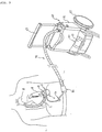
- Fig. 3 shows a case in which the portable artificial-heart drive system is implanted in the human body.
- the blood pump 1 includes a pump base section 10 having a cylindrical motor portion 11, and a pump section 12 connected to the pump base section 10.
- the pump section 12 includes a pump vane 14 to be driven via the rotation shaft 13 extending from the motor portion 11, and a casing 15 connected to the pump base section 10 so as to cover the pump vane 14.
- Blood in the left ventricle A flows into the casing 15 from an inlet 16 formed at the end of the casing 15, is supplied with energy by the pump vane 14 in the casing 15, and is discharged to the aorta B via an outlet 17 formed on the side of the casing 15 and an artificial blood vessel C.
- the blood seal 18 being an end-face contact type (hereinafter referred to as mechanical seal) is located between the pump base section 10 and the pump vane 14 so that it prevents the bearing 19 of the rotation shaft 13 from adhesion due to the entry of a blood ingredient.
- an inlet 8 and an outlet 9 for the purge solution are formed in the pump base section 10, and connected to the purge solution circulating device, which will be described later, via the purge tubes 24 and 25.
- the purge solution is circulated inside the mechanical seal 18 by the purge solution circulating means 20, and operates to lubricate and cool the contact surface of mechanical seal, and to remove by diffusion very small quantities of blood ingredients that enter the purge solution, whereby the contact surface of the mechanical seal 18 and the bearing 19 are always kept clean.
- the blood seal 18 is not limited to the mechanical seal, and other contact seals, such as an oil seal, may be available.
- the system drive section 45 which includes the purge solution circulating means 20 for supplying purge solution to the mechanical seal 18 located inside the blood pump 1, the pump control means 30 for electrically controlling the drive of the blood pump 1 via the motor cable 71, the display means 40 for displaying the operation states of the aforementioned means and data thereon, the communication means 50 for exchanging information with the outside, the power supply means 33 for supplying electric power to the aforementioned means, and the control means 100 for controlling the aforementioned means, is constructed inside a compact housing 61, and mounted on the manual transport section 60 having wheels 62 and a handle 63.
- the transport section 60 in this example is shaped like a handcart, it may take any shape that is suited for the condition and living environment of the patient, for example, a wheel chair or a bag. Furthermore, the transport section 60 may be a motor-driven type in which the wheels 62 are equipped with a motor.
- Fig. 4 is a structural diagram of the pump control means 30.
- the control means 100 is formed of a one-board microcomputer or the like that includes an arithmetic unit 101, a memory 102, and various types of interfaces 103.
- Output signals which are input to the arithmetic unit 101 from sensors in the above means via an A/D converter 104, are processed according to a control program stored in a ROM of the memory 102, and the calculation result is output via a D/A converter 105.
- data is exchanged with arithmetic units 101 of the constituents via the interfaces 103.
- the data is stored in a RAM of the memory 102, and displayed by the display means 40.
- the blood pump 1 is usually controlled by the control means 100.
- the control means 100 calculates a position signal corresponding to the rotational position of a rotor 106 in the pump control.
- the rotation of the rotor 106 is detected based on the output from a Hall sensor 108 located inside the motor portion 11 of the blood pump 1, and the arithmetic unit 101 of the control means 100 performs calculation so that the number of revolutions of the blood pump 1 is constant.
- Power suppliers 107 inside the connecting terminal 80 supply stator windings 109 of the motor with electric power according to the position signal.
- the driving can be performed without a sensor, and the control method is not limited to constant revolution control.
- the backup pump control means 30 is located in the connecting terminal 80, and the control means 100 and the backup pump control means 30 mutually monitor their arithmetic units 101 via the interfaces 103. For example, when trouble occurs to the arithmetic unit 101 of the control means 100, the control of the blood pump 1 is switched to the backup pump control means 30, and the arithmetic unit 101 of the control means 100 is reset via the interface 103. After the arithmetic unit 101 of the control means 100 is reset and returned to a normal state, the control of the heart pump is transferred to the control means 100, and the backup pump control means 30 monitors only the arithmetic unit 101 of the control means 100. Conversely, when trouble of the arithmetic unit 101 of the backup pump control means 30 is detected, the backup pump control means 30 is reset.
- pump control means 30 and the power supply means 33 of this example are provided in two systems, they are not limited to two systems, and may be provided in more systems.
- the kinetic load detecting mechanism 31 is formed of a rotation detector 32 mounted on the wheel 62 of the transport section 60.
- the control means 100 calculates the speed of travel of the portable artificial-heart drive system based on a signal from the rotation detector 32, and increases or decreases the number of revolutions of the motor in the blood pump 1 in response to the speed of travel. Since the momentum of the patient can be easily detected, the quality of life of the patient can be improved.
- control may be exerted by calculating the heart rate based on the change in load of the motor in the blood pump 1 depending on the heart beat of the living body and increasing or decreasing the number of revolutions of the motor in the blood pump 1 in response to the change in heart rate.
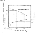
- Fig. 5 explains the method of estimating the heart rate of the living body, and shows the characteristics in a case in which the centrifugal pump shown in Fig. 2 is controlled so that the number of revolutions is constant.
- the load on the motor portion 11 substantially varies with the change in pressure inside the left ventricle A owing to the heart beat of the living body.
- the difference between the internal pressure of the left ventricle A corresponding to the inflow pressure of the blood pump 1 and the pressure in the aorta B corresponding to the outflow pressure changes with the heart beat between P1 and P2
- the flow rate of the blood pump 1 changes between Q1 and Q2.
- the current value of the blood pump 1 also changes between I1 and I2.
- the heart rate of the living body can be estimated by monitoring the cycle of the change in current value.
- a similar characteristic is provided in a case in which the blood pump 1 is controlled so that the current value is constant, and the heart rate of the living body can be estimated based on the change in number of revolutions of the blood pump 1.
- the above-mentioned control methods may be used separately or simultaneously.
- the detection means can be achieved in a considerably simple structure, it is possible to limit the malfunction and failure, and to thereby improve the quality of life of the patient.
- Fig. 6 is a structural diagram of the power supply means 33.
- the power supply means 33 includes a power supply means control section 34 for controlling the switching of power sources to be used and the charge and discharge of built-in batteries 35, the plural batteries 35 formed of nickel hydrogen secondary batteries or lithium ion secondary batteries, a charger 36, and the like, and it is located in the system drive section 45 and the connecting terminal 80.
- a power supply means control section 34 for controlling the switching of power sources to be used and the charge and discharge of built-in batteries 35, the plural batteries 35 formed of nickel hydrogen secondary batteries or lithium ion secondary batteries, a charger 36, and the like, and it is located in the system drive section 45 and the connecting terminal 80.
- an external power source 37 such as AC power source or an automobile-installed power source
- a battery 35 in the connecting terminal 80 is used when the power supply means 33 in the system drive section 45 cannot be used, for example, when the system drive section 45 is damaged. In normal operations, the power supply means 33 in the system drive section 45 is used. Furthermore, when the quantity of electricity remaining in the batteries 35 in the system drive section 45 falls below a specified value, the supply of power to the means that constitute the system drive section 45 is stopped, and power is supplied only to the backup pump control means 30 in the connecting terminal 80, whereby the driving time of the portable drive system is extended.
- the built-in batteries 35 are provided with battery control circuits 38, respectively, each of which monitors the remaining quantity in the battery 35, the number of times of charge and discharge, the voltage, and the like.
- the power supply means control section 34 receives the aforesaid data from the battery control circuits 38, and sequentially and selectively controls the charge and discharge of the batteries.
- the output from sensors 39, which are provided for the batteries to detect the temperatures thereof, is monitored by the control means 100, thereby preventing the combustion and explosion resulting from extraordinary heat generation of the batteries 35.
- the control means 100 and the arithmetic unit 101 of the power supply means 33 mutually exchange information about operations of their constituents and monitor the operation states thereof via the interfaces 103.
- the arithmetic unit 101 of the control means 100 receives, from the arithmetic unit 101 of the power supply means 33, information, such as the type of power source to be used, the remaining quantity and the number of times of charge and discharge of the batteries 35, the voltage, and the temperature of the batteries 35, and it makes a judgement on the operations.
- the information is displayed on the display means 40.
- the arithmetic unit 101 of the power supply means control section 34 is out of order, it is reset via the interface 103.
- the configuration of the control means 100 is common to the aforementioned one, and therefore, a description thereof is omitted.
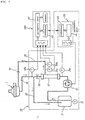
- Fig. 7 is a structural diagram of the purge solution circulating means 20.
- the purge solution circulating means 20 supplies purge solution to the contact surface of the aforementioned mechanical seal by circulating it in order to maintain the shaft sealing of the rotation shaft 13 in the blood pump 1 with respect to blood.
- Purge solution with disinfectant added therein is caused by a purge solution circulating pump 22, which circulates the purge solution, to pass from a reservoir 21 for storing the purge solution through a filter 23 for filtering the purge solution.
- a purge solution circulating pump 22 which circulates the purge solution, to pass from a reservoir 21 for storing the purge solution through a filter 23 for filtering the purge solution.
- One part of the purge solution passes through the purge tube 24, flows into the blood pump 1 implanted in the body, reaches the contact surface of the mechanical seal, and then, returns to the reservoir 21 via the purge tube 25.
- the other part of the purge solution flowing out of the filter 23 passes through a bypass channel 26 and returns to the reservoir 21.
- valve mechanisms 75 are located on the purge tubes 24 and 25.
- the valve mechanisms 75 close the purge tubes 24 and 25 the moment the circulation of the purge solution stops, and holds the purge solution in the blood pump 1, thereby maintaining the function of the blood seal 18.
- a protein ingredient of blood which enters the purge solution by diffusion via a lubricating thin film on the contact surface of the mechanical seal in the blood pump 1, is filtered by the filter 23 located on the channel where the purge solution circulates. Therefore, the purge solution is always kept clean, and the bearing 19 of the rotation shaft 13 in the blood pump 1 can be prevented from seizure. Moreover, when an ultrafilter membrane is used as the filter 23, it is possible to remove bacteria, viruses, and bacteriotoxin, and to sterilize and detoxify the purge solution.
- hypochlorous acid can sterilize almost all kinds of bacteria and viruses in low concentration, and combines with an organic matter in the living body to form an organochlorine compound, thereby performing detoxification.
- the reservoir 21 and the filter 23 are disinfected by adding a disinfectant in the purge solution.
- the purge solution that flows in the blood pump 1 of the artificial heart is disinfected physically and chemically, which achieves double safeguards.
- the pore size of the filter 23 using an ultrafilter membrane is set at a molecular weight of 340,000 or less.
- the cross flow circulation route in which the bypass channel 26 is formed to prevent the clogging of the filter 23 serves three functions as follows.
- the bypass channel 26 in the purge solution circulating means 20 having the cross flow circulation route functions as a safety valve in such an emergency, and keeps the increase in pressure of the purge solution less than a predetermined value, thereby preventing the purge solution circulating means from breaking.
- the flow rate of the purge solution flowing in the purge solution circulating means located outside the body increases by an amount corresponding to the flow rate of the purge solution passing through the bypass channel 26. Since the purge solution is cooled by heat dissipation that results from the temperature difference between the purge solution and outside air, the radiation effect of the purge solution improves as the flow rate of the purge solution increases.
- the purge solution decreases because it leaks from the contact surface of the mechanical seal in a very small quantity, there is a need to replace the reservoir 21 at fixed periods. Moreover, if protein adheres to the filter 23, it may cause the proliferation of bacteria, and therefore, there is also a need to replace the filter 23 at fixed periods.
- the reservoir 21, the purge solution circulating pump 22, and the filter 23 using an ultrafilter membrane may be combined into a unit so as to make periodical replacement considerably easy and clean.
- the purge solution circulating pump 22 is a small-sized positive displacement pump that has high efficiency and high reliability, does not need a seal, and can be disinfected.
- a roller pump is used, and it has a structure in which purge solution is sent out from a pipe, where it flows, by stroking the pipe from the outside.
- the roller pump is preferable because only the inner side of the pipe is in contact with the purge solution.
- other small pumps such as a diaphragm pump and a gear pump, may be used.
- Sensors 27a and 27b for detecting the pressure are mounted at the entrance and exit of the filter 23, and the outputs from the sensors 27a and 27b are monitored by the control means 100, whereby the choking of the purge solution circulating circuit, the clogging of the filter 23, and the like are monitored.
- a sensor 28a for detecting the temperature of the purge solution which circulates from the blood pump 1 to the purge solution circulating means 20, is mounted on the purge tube 25, and the operating conditions of the purge solution circulating pump 22 are controlled so that the temperature of the purge solution does not reach the heat denaturation temperature of the protein ingredients in the blood.
- the arithmetic unit 101 of the control means 100 calculates the operating conditions, and the arithmetic unit 101 of the purge solution circulating means control section 110 controls the purge solution circulating pump 22 according to the instructions from the control means 100.
- a sensor 28b for detecting the temperature of the purge solution which circulates from the purge solution circulating means 20 to the blood pump 1 is mounted on the purge tube 24 to compare the temperatures of the purge solution that flows into the blood pump 1 and the purge solution that flows out therefrom, whereby the heat flow between the living body and the portable artificial-heart drive system can be grasped.
- the operating conditions of the purge solution circulating means 20 can be grasped in more detail by adding a flow rate sensor, a blood sensor and the like besides the pressure sensor and the temperature sensor.
- the reservoir 21 containing purge solution is shaped like a flexible bag, so that it can respond to its change in capacity with consumption of purge solution, in altitude with the movement of the transport section 60, and the like.
- the reservoir 21 is provided with a sensor 29 for detecting the volume of purge solution, and the output from the sensor 29 is monitored by the control means 100, thereby monitoring the leakage of the purge solution.
- the control means 100 monitors the arithmetic unit 101 of the purge solution circulating means control section 110 via the interface 103, and resets it when an error occurs thereto.
- the display means 40 includes a display section 41 for displaying information, and an input means (not shown) for switching displayed information and inputting data.
- the display section 41 always displays information about the operations of the constituents of the artificial heart that is processed by the control means 100. When the operation information deviates from set values, an alarm is given, and detailed information, such as a countermeasure, is displayed on the display section 41.
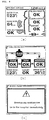
- Figs. 8(a) to 8(c) show examples of displays on the display section 41.
- Fig. 8(a) shows a usual display state.
- the uppermost section indicates the number of days the present portable artificial-heart drive system has been in use.
- the left column indicates the outer temperature, the heart rate, and the operating state of the connecting terminal 80 in that order from the top.
- the right column indicates the states of the blood pump 1, the purge solution circulating means 20, and the battery 35, in that order from the top.
- the bottom right section indicates the charge or discharge, and the use of the external power source 37.
- basic information about the operations mentioned above is displayed, and more detailed information about the operations of the constituents may be displayed through the input means.
- Fig. 8(b) shows detailed operation states of the purge solution circulating means 20.
- the upper section indicates the operation states of the blood pump 1, the reservoir 21, the purge solution circulating pump 22, and the filter 23 that constitute the purge solution circulating means 20, and the purge tubes 24 and 25.
- the lower section indicates, from the left, the outer temperature, the operation state of the arithmetic unit 101 in the purge solution control means 100, and the temperature of the purge solution.
- Fig. 8(c) When abnormal conditions are encountered, the message shown in Fig. 8(c) is displayed, and details of the abnormal conditions may be displayed by switching through the input means (not shown).
- operating parameters may be changed through the input means.
- the communication means 50 has a connecting terminal for connection to a telephone line, and can make connection to a computer in a hospital or the like.
- the portable artificial-heart drive system can be controlled and monitored by a computer in the hospital.
- the mobile communication means 50 such as a portable telephone
- information about the portable artificial-heart drive system is appropriately transferred to the hospital or the like, and appropriate instructions are transferred back. Therefore, the safety of life of the patient outside the hospital is further increased.
- Fig. 9 shows an example of the connecting terminal 80.
- the connecting terminal 80 connects the internally embedded part and the externally exposed part of the connecting section 70.
- the connecting terminal 80 is fixed to a belt-like stomach band 81. Since the externally exposed part of the connecting section 70 is expandable, external force caused by movement of the body is not directly transmitted to the internally embedded part of the connecting section 70.
- the connecting terminal 80 has a display section 41 on which information, such as the number of revolutions of the motor in the blood pump 1 and the amount of electricity in the battery, is sequentially displayed by switching using a control button 42. When an error occurs, it is announced by the illumination of an error indicator 43 and an alarm.
- the pump control means 30 and the power supply means 33 for backup are built in the connecting terminal 80.
- the blood pump 1 is driven by the backup pump control means 30 and the backup power supply means 33 inside the connecting terminal 80.
- the externally exposed part of the connecting section 70 is connected so that it splits at the connecting terminal 80.
- the purge tubes 24 and 25 and backup terminals of the motor cable 71 are also built in the connecting terminal 80, and easy access is possible even during the maintenance of the system drive section 45.
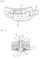
- Fig. 10 shows an example of the skin button section 90.
- the skin button section 90 is a structure composed of a plurality of carbon fibers having many pores on the surface thereof, and includes a cylindrical portion 91 and a flange portion 92.
- the flange portion 92 is located between the musculus rectus abdominis D and the vagina musculi recti abdominis E, and one end of the cylindrical portion 91 reaches the epidermis F.
- the skin button section 90 firmly adheres to the tissue that is in contact therewith, prevents the separation of the connecting section 70 due to the movement of the body, and thereby avoids infectious diseases via the connecting section 70.
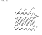
- Fig. 11 shows an example of the connecting section 70.
- the connecting section 70 includes the purge tubes 24 and 25, the motor cable 71, and a protective tube 72 for covering them.
- the purge tubes 24 and 25 and the motor cable 71 are helically formed, the protective tube 72 is shaped like a bellows, and both are expandable so as not to hinder the movement of the body of the patient.
- the expansion amount of the protective tube 72 is set smaller than that of the purge tubes 24 and 25 and the motor cable 71, and the maximum expansion amount of the protective tube 72 limits the expansion amount of the connecting section 70, whereby the purge tubes 24 and 25 and the motor cable 71 are prevented from breaking.
- the protective tube 72 is made of a material that is resistant to breakage, such as Kevlar fiber, and the surface thereof is waterproofed. Still furthermore, a plurality of circular rings 73 made of metal, resin or the like are embedded in the protective tube 72 in order to prevent the purge tubes 24 and 25 and the motor cable 71 from deforming and breaking when load directly acts on the connecting section 70.
- the pump control means, the purge solution circulating means, the control means, the display means, the communication means, and the power supply means are made compact and mounted on the transport section, the life outside the hospital is permitted.
- a plurality of pump control means and power supply means make it possible to maintain safe blood circulation under abnormal conditions.
- the addition of disinfectant in the purge solution makes it possible to prevent blood from coagulating, to remove and sterilize miscellaneous bacteria as well as the ultrafilter, and to thereby circulate a clean purge solution.
- the number of revolutions of the blood pump can be controlled by the control means in accordance with the kinetic load, blood circulation can be always kept stable and safe, and the drive condition of the artificial heart can be monitored through the display means. Therefore, the patient can manage himself or herself, and the patient or a third person can respond to abnormal conditions. Moreover, since the communication means permits the doctor and the hospital to quickly respond to abnormal conditions of the artificial heart, the safety of life outside the hospital is substantially improved.
- the connecting terminal attached to a belt like a stomach band permits the patient to live everyday life without worrying about its appearance. This also makes it possible to reduce the influence of the body movement on the epidermis.
- the skin button section formed of carbon fibers is embedded in the body near the epidermis, it firmly adheres to cells, thereby preventing infectious diseases.
- the connecting section has both expandability and strength, ease of use and safety can be achieved.
Landscapes
- Health & Medical Sciences (AREA)
- Engineering & Computer Science (AREA)
- Heart & Thoracic Surgery (AREA)
- Cardiology (AREA)
- Biomedical Technology (AREA)
- Anesthesiology (AREA)
- Mechanical Engineering (AREA)
- Hematology (AREA)
- Life Sciences & Earth Sciences (AREA)
- Animal Behavior & Ethology (AREA)
- General Health & Medical Sciences (AREA)
- Public Health (AREA)
- Veterinary Medicine (AREA)
- Medical Informatics (AREA)
- External Artificial Organs (AREA)
Applications Claiming Priority (3)
| Application Number | Priority Date | Filing Date | Title |
|---|---|---|---|
| JP9200638A JPH1085322A (ja) | 1996-07-26 | 1997-07-25 | 人工心臓の可搬駆動システム |
| JP20063897 | 1997-07-25 | ||
| PCT/JP1998/000319 WO1999004834A1 (en) | 1997-07-25 | 1998-01-26 | Portable drive system for artificial heart |
Publications (2)
| Publication Number | Publication Date |
|---|---|
| EP0928613A1 true EP0928613A1 (de) | 1999-07-14 |
| EP0928613A4 EP0928613A4 (de) | 2001-01-17 |
Family
ID=16427727
Family Applications (1)
| Application Number | Title | Priority Date | Filing Date |
|---|---|---|---|
| EP98900753A Withdrawn EP0928613A4 (de) | 1997-07-25 | 1998-01-26 | Tragbares antriebssystem für ein kunstliches herz |
Country Status (3)
| Country | Link |
|---|---|
| US (1) | US6123726A (de) |
| EP (1) | EP0928613A4 (de) |
| WO (1) | WO1999004834A1 (de) |
Cited By (2)
| Publication number | Priority date | Publication date | Assignee | Title |
|---|---|---|---|---|
| US8282359B2 (en) | 1999-04-23 | 2012-10-09 | Thoratec Corporation | Rotary blood pump and control system therefor |
| US8465410B2 (en) | 2006-01-27 | 2013-06-18 | Circulite, Inc. | Heart assist system |
Families Citing this family (98)
| Publication number | Priority date | Publication date | Assignee | Title |
|---|---|---|---|---|
| KR100403548B1 (ko) * | 2001-08-29 | 2003-11-01 | 안태영 | 의료기구용 발전기 |
| US6942672B2 (en) | 2001-10-23 | 2005-09-13 | Vascor, Inc. | Method and apparatus for attaching a conduit to the heart or a blood vessel |
| US20040172113A1 (en) * | 2001-11-26 | 2004-09-02 | Kenji Yamazaki | Tube unit and a blood pump system |
| US6802806B2 (en) * | 2002-09-23 | 2004-10-12 | Cleveland Clinic Foundation | Apparatus for use with an inflow cannula of ventricular assist device |
| EP1486217B1 (de) * | 2003-06-12 | 2010-05-12 | Terumo Kabushiki Kaisha | Pumpensystem für ein künstliches Herz und Steuerungsgerät dafür |
| US7494459B2 (en) * | 2003-06-26 | 2009-02-24 | Biophan Technologies, Inc. | Sensor-equipped and algorithm-controlled direct mechanical ventricular assist device |
| US7682301B2 (en) | 2003-09-18 | 2010-03-23 | Thoratec Corporation | Rotary blood pump |
| US20070131573A1 (en) * | 2004-09-10 | 2007-06-14 | Boyles Kathleen A | Container |
| KR100599986B1 (ko) * | 2004-10-23 | 2006-07-13 | 고려대학교 산학협력단 | 혈액 펌프 구동기 및 이를 구비하는 혈액 펌프 시스템 |
| EP1812094B1 (de) * | 2004-11-16 | 2011-08-17 | Micromed Technology, Inc. | Datenmonitor auf Abstand für ein Herzpumpensystem |
| DE102005017546A1 (de) * | 2005-04-16 | 2006-10-19 | Impella Cardiosystems Gmbh | Verfahren zur Steuerung einer Blutpumpe |
| US20100152523A1 (en) * | 2005-11-28 | 2010-06-17 | Myocardiocare, Inc. | Method and Apparatus for Minimally Invasive Direct Mechanical Ventricular Actuation |
| US20070142696A1 (en) * | 2005-12-08 | 2007-06-21 | Ventrassist Pty Ltd | Implantable medical devices |
| US20070231135A1 (en) | 2006-03-31 | 2007-10-04 | Orqis Medical Corporation | Rotary Blood Pump |
| AU2008261920A1 (en) | 2007-06-06 | 2008-12-18 | Worldheart Corporation | Wearable VAD controller with reserve battery |
| JP5201887B2 (ja) * | 2007-06-20 | 2013-06-05 | テルモ株式会社 | 人工心臓用血液ポンプシステムおよび機器監視システム |
| US7794384B2 (en) * | 2007-12-07 | 2010-09-14 | Terumo Heart, Inc. | Dual communication interface for artificial heart system |
| JP5250755B2 (ja) | 2008-03-25 | 2013-07-31 | 株式会社サンメディカル技術研究所 | 補助人工心臓ポンプ駆動装置及び補助人工心臓システム |
| US7811318B2 (en) * | 2008-04-23 | 2010-10-12 | Syncardia Systems, Inc. | Apparatus and method for pneumatically driving an implantable medical device |
| EP2292282B1 (de) | 2008-06-23 | 2017-11-15 | Thoratec Corporation | Blutpumpe |
| WO2010025411A2 (en) * | 2008-08-28 | 2010-03-04 | Orqis Medical Corporation | Implantable heart assist system |
| CN102239334B (zh) | 2008-12-08 | 2015-03-04 | 胸腔科技有限公司 | 离心式泵装置 |
| JP5378010B2 (ja) | 2009-03-05 | 2013-12-25 | ソラテック コーポレーション | 遠心式ポンプ装置 |
| CN102341600B (zh) | 2009-03-06 | 2014-12-10 | 胸腔科技有限公司 | 离心式泵装置 |
| EP3490122B1 (de) | 2009-07-29 | 2021-01-27 | Thoratec Corporation | Rotationsantriebsvorrichtung und zentrifugalpumpenvorrichtung |
| US8628460B2 (en) * | 2009-09-21 | 2014-01-14 | Heartware, Inc. | Hard-wired implanted controller system |
| US20110196189A1 (en) * | 2010-02-09 | 2011-08-11 | Myocardiocare, Inc. | Extra-cardiac differential ventricular actuation by inertial and baric partitioning |
| JP5443197B2 (ja) | 2010-02-16 | 2014-03-19 | ソラテック コーポレーション | 遠心式ポンプ装置 |
| WO2011118325A1 (ja) | 2010-03-26 | 2011-09-29 | テルモ株式会社 | 遠心式血液ポンプ装置 |
| JP5681403B2 (ja) | 2010-07-12 | 2015-03-11 | ソーラテック コーポレイション | 遠心式ポンプ装置 |
| WO2012012552A1 (en) | 2010-07-22 | 2012-01-26 | Thoratec Corporation | Controlling implanted blood pumps |
| JP5577506B2 (ja) | 2010-09-14 | 2014-08-27 | ソーラテック コーポレイション | 遠心式ポンプ装置 |
| EP2693609B1 (de) | 2011-03-28 | 2017-05-03 | Thoratec Corporation | Dreh- und antriebsvorrichtung und zentrifugalpumpvorrichtung damit |
| WO2012158560A2 (en) * | 2011-05-13 | 2012-11-22 | Maquet Cardiovascular Llc | Portable and modular transportation unit with improved transport capabilities |
| JP6083929B2 (ja) | 2012-01-18 | 2017-02-22 | ソーラテック コーポレイション | 遠心式ポンプ装置 |
| WO2014018971A1 (en) | 2012-07-27 | 2014-01-30 | Thoratec Corporation | Resonant power transfer systems with protective algorithm |
| US10383990B2 (en) | 2012-07-27 | 2019-08-20 | Tc1 Llc | Variable capacitor for resonant power transfer systems |
| WO2014018967A1 (en) | 2012-07-27 | 2014-01-30 | Thoratec Corporation | Self-tuning resonant power transfer systems |
| WO2014018973A1 (en) | 2012-07-27 | 2014-01-30 | Thoratec Corporation | Resonant power transmission coils and systems |
| US10525181B2 (en) | 2012-07-27 | 2020-01-07 | Tc1 Llc | Resonant power transfer system and method of estimating system state |
| US9592397B2 (en) | 2012-07-27 | 2017-03-14 | Thoratec Corporation | Thermal management for implantable wireless power transfer systems |
| US9805863B2 (en) | 2012-07-27 | 2017-10-31 | Thoratec Corporation | Magnetic power transmission utilizing phased transmitter coil arrays and phased receiver coil arrays |
| US10291067B2 (en) | 2012-07-27 | 2019-05-14 | Tc1 Llc | Computer modeling for resonant power transfer systems |
| US9943635B2 (en) * | 2012-09-05 | 2018-04-17 | Terumo Kabushiki Kaisha | Extracorporeal circulation device and control method |
| EP2902046B1 (de) * | 2012-09-26 | 2018-01-10 | Terumo Kabushiki Kaisha | Steuerung für eine lebensunterstützungsvorrichtung |
| US9364596B2 (en) | 2013-01-04 | 2016-06-14 | HeartWave, Inc. | Controller and power source for implantable blood pump |
| US9371826B2 (en) | 2013-01-24 | 2016-06-21 | Thoratec Corporation | Impeller position compensation using field oriented control |
| US9556873B2 (en) | 2013-02-27 | 2017-01-31 | Tc1 Llc | Startup sequence for centrifugal pump with levitated impeller |
| US10373756B2 (en) | 2013-03-15 | 2019-08-06 | Tc1 Llc | Malleable TETs coil with improved anatomical fit |
| WO2014145664A1 (en) | 2013-03-15 | 2014-09-18 | Thoratec Corporation | Integrated implantable tets housing including fins and coil loops |
| US10052420B2 (en) | 2013-04-30 | 2018-08-21 | Tc1 Llc | Heart beat identification and pump speed synchronization |
| US9713663B2 (en) | 2013-04-30 | 2017-07-25 | Tc1 Llc | Cardiac pump with speed adapted for ventricle unloading |
| US20150021878A1 (en) * | 2013-07-18 | 2015-01-22 | Variety Children's Hospital D/B/A Miami Children's Hospital | Portable cardiopulmonary support cart systems |
| EP3069358B1 (de) | 2013-11-11 | 2019-06-12 | Tc1 Llc | Resonante stromübertragungsspule mit einem scharnier |
| EP3072210B1 (de) | 2013-11-11 | 2023-12-20 | Tc1 Llc | Resonante stromübertragungssysteme mit kommunikation |
| WO2015070200A1 (en) | 2013-11-11 | 2015-05-14 | Thoratec Corporation | Resonant power transfer systems with communications |
| WO2015134871A1 (en) | 2014-03-06 | 2015-09-11 | Thoratec Corporation | Electrical connectors for implantable devices |
| US9623161B2 (en) | 2014-08-26 | 2017-04-18 | Tc1 Llc | Blood pump and method of suction detection |
| EP3826104B1 (de) | 2014-09-22 | 2023-05-03 | Tc1 Llc | Antennenentwürfe zur kommunikation zwischen einem drahtlos betriebenen implantat mit einer externen vorrichtung ausserhalb des körpers |
| WO2016053688A1 (en) | 2014-10-01 | 2016-04-07 | Heartware, Inc. | Backup controller system with updating |
| EP3204989B1 (de) | 2014-10-06 | 2019-08-21 | Tc1 Llc | Mehrachsiger steckverbinder für implantierbare vorrichtungen |
| EP4643926A3 (de) | 2015-02-11 | 2025-12-24 | Tc1 Llc | Herzschlagidentifizierung und pumpengeschwindigkeitssynchronisierung |
| WO2016130944A1 (en) | 2015-02-12 | 2016-08-18 | Thoratec Corporation | System and method for controlling the position of a levitated rotor |
| US10371152B2 (en) | 2015-02-12 | 2019-08-06 | Tc1 Llc | Alternating pump gaps |
| WO2016130989A1 (en) | 2015-02-13 | 2016-08-18 | Thoratec Corporation | Impeller suspension mechanism for heart pump |
| US10148126B2 (en) | 2015-08-31 | 2018-12-04 | Tc1 Llc | Wireless energy transfer system and wearables |
| EP3902100A1 (de) | 2015-10-07 | 2021-10-27 | Tc1 Llc | Resonante leistungsübertragungssysteme mit effizienzoptimierung basierend auf empfängerimpedanz |
| US10117983B2 (en) | 2015-11-16 | 2018-11-06 | Tc1 Llc | Pressure/flow characteristic modification of a centrifugal pump in a ventricular assist device |
| WO2017087728A1 (en) | 2015-11-20 | 2017-05-26 | Tc1 Llc | Improved connectors and cables for use with ventricle assist systems |
| WO2017087785A1 (en) | 2015-11-20 | 2017-05-26 | Tc1 Llc | Energy management of blood pump controllers |
| CN108697836B (zh) | 2016-02-25 | 2024-10-25 | 心脏器械股份有限公司 | 具有车辆适配器和电池的电源 |
| US10898292B2 (en) | 2016-09-21 | 2021-01-26 | Tc1 Llc | Systems and methods for locating implanted wireless power transmission devices |
| WO2018136592A2 (en) | 2017-01-18 | 2018-07-26 | Tc1 Llc | Systems and methods for transcutaneous power transfer using microneedles |
| EP4732889A2 (de) | 2017-06-07 | 2026-04-29 | Supira Medical, Inc. | Vorrichtungen, systeme und verfahren zur bewegung intravaskulärer flüssigkeiten |
| US11511103B2 (en) | 2017-11-13 | 2022-11-29 | Shifamed Holdings, Llc | Intravascular fluid movement devices, systems, and methods of use |
| WO2019135890A1 (en) | 2018-01-04 | 2019-07-11 | Tc1 Llc | Systems and methods for elastic wireless power transmission devices |
| JP7410034B2 (ja) | 2018-02-01 | 2024-01-09 | シファメド・ホールディングス・エルエルシー | 血管内血液ポンプならびに使用および製造の方法 |
| US11389641B2 (en) * | 2018-03-21 | 2022-07-19 | Tc1 Llc | Modular flying lead cable and methods for use with heart pump controllers |
| WO2020028537A1 (en) | 2018-07-31 | 2020-02-06 | Shifamed Holdings, Llc | Intravascaular blood pumps and methods of use |
| WO2020073047A1 (en) | 2018-10-05 | 2020-04-09 | Shifamed Holdings, Llc | Intravascular blood pumps and methods of use |
| CN112206410A (zh) * | 2019-07-12 | 2021-01-12 | 航天泰心科技有限公司 | 血泵控制电路及其控制方法、装置和心室辅助装置 |
| WO2021011473A1 (en) | 2019-07-12 | 2021-01-21 | Shifamed Holdings, Llc | Intravascular blood pumps and methods of manufacture and use |
| US11654275B2 (en) | 2019-07-22 | 2023-05-23 | Shifamed Holdings, Llc | Intravascular blood pumps with struts and methods of use and manufacture |
| EP4010046A4 (de) | 2019-08-07 | 2023-08-30 | Calomeni, Michael | Katheterblutpumpen und zusammenklappbare pumpengehäuse |
| WO2021062260A1 (en) | 2019-09-25 | 2021-04-01 | Shifamed Holdings, Llc | Catheter blood pumps and collapsible blood conduits |
| EP4034192B1 (de) | 2019-09-25 | 2025-12-24 | Supira Medical, Inc. | Intravaskuläre blutpumpensysteme und verfahren zur verwendung und steuerung davon |
| EP4034221B1 (de) | 2019-09-25 | 2024-11-13 | Shifamed Holdings, LLC | Katheterblutpumpen und zusammenklappbare pumpengehäuse |
| EP4072650A4 (de) | 2019-12-11 | 2024-01-10 | Shifamed Holdings, LLC | Absteigende aorten- und hohlvenenblutpumpen |
| US12599758B2 (en) | 2019-12-19 | 2026-04-14 | Shifamed Holdings, Llc | Intravascular blood pumps, motors, and fluid control |
| US12478475B2 (en) | 2020-10-01 | 2025-11-25 | Lifebridge Technologies Llc | Single tube pressurization system for a heart pump |
| US12440338B2 (en) | 2020-10-01 | 2025-10-14 | Lifebridge Technologies Llc | Minimally invasive heart pump with modular adjustable construct insertion |
| US12263332B2 (en) | 2022-09-13 | 2025-04-01 | Lifebridge Technologies Llc | Material characteristics ideal for providing either partial or total mechanical support to the failing or arrested heart and method for developing ideal characteristics for underlying cardiac disorders |
| US12478773B2 (en) | 2020-10-01 | 2025-11-25 | Lifebridge Technologies Llc | Dynamic drive system for cardiac systolic and diastolic assist |
| US12115363B1 (en) | 2023-08-10 | 2024-10-15 | Lifebridge Technologies Llc | System and method for introducing a construct either on or around the surface of the heart |
| US11383076B2 (en) | 2020-10-01 | 2022-07-12 | Lifebridge Technologies, Llc | Pump regulation based on heart size and function |
| US11896812B1 (en) | 2023-01-27 | 2024-02-13 | Lifebridge Technologies Llc | Versatile modular heart pump for non-blood contacting ventricular function augmentation |
| CN115040711B (zh) * | 2022-04-24 | 2025-08-26 | 北京机械设备研究所 | 一种手动和自动一体的血泵驱动装置 |
| CN117599329A (zh) * | 2023-11-29 | 2024-02-27 | 上海焕擎医疗科技有限公司 | 用于心脏泵的手柄、心室辅助装置及可拆卸心室辅助装置 |
Family Cites Families (14)
| Publication number | Priority date | Publication date | Assignee | Title |
|---|---|---|---|---|
| US4704121A (en) * | 1983-09-28 | 1987-11-03 | Nimbus, Inc. | Anti-thrombogenic blood pump |
| US4756302A (en) * | 1986-11-20 | 1988-07-12 | Novacor Medical Corporation | Blood pumping system and method |
| US5147392A (en) * | 1987-03-31 | 1992-09-15 | Aisin Seiki K.K. | Pumping drive unit |
| US5041086A (en) * | 1987-12-04 | 1991-08-20 | Pacesetter Infusion, Ltd. | Clinical configuration of multimode medication infusion system |
| US5020516A (en) * | 1988-03-31 | 1991-06-04 | Cardiopulmonary Corporation | Circulatory assist method and apparatus |
| US4927407A (en) * | 1989-06-19 | 1990-05-22 | Regents Of The University Of Minnesota | Cardiac assist pump with steady rate supply of fluid lubricant |
| CH684879A5 (de) * | 1992-03-27 | 1995-01-31 | Wilhelm Servis | Herzunterstützende oder herzersetzende Blutpumpe. |
| US5676651A (en) * | 1992-08-06 | 1997-10-14 | Electric Boat Corporation | Surgically implantable pump arrangement and method for pumping body fluids |
| US5376114A (en) * | 1992-10-30 | 1994-12-27 | Jarvik; Robert | Cannula pumps for temporary cardiac support and methods of their application and use |
| EP1402908A3 (de) * | 1994-04-15 | 2005-04-27 | Allegheny-Singer Research Institute | Blutpumpe und Herstellungsverfahren |
| US5569186A (en) * | 1994-04-25 | 1996-10-29 | Minimed Inc. | Closed loop infusion pump system with removable glucose sensor |
| US5509902A (en) * | 1994-07-25 | 1996-04-23 | Raulerson; J. Daniel | Subcutaneous catheter stabilizing devices and methods for securing a catheter using the same |
| US5501216A (en) * | 1994-11-23 | 1996-03-26 | Byrd; Timothy N. | Tracheostomy tube holder and associated tube holding method |
| US5776110A (en) * | 1996-01-26 | 1998-07-07 | United States Surgical Corporation | Thoracic port |
-
1998
- 1998-01-26 US US09/147,996 patent/US6123726A/en not_active Expired - Lifetime
- 1998-01-26 WO PCT/JP1998/000319 patent/WO1999004834A1/ja not_active Ceased
- 1998-01-26 EP EP98900753A patent/EP0928613A4/de not_active Withdrawn
Cited By (3)
| Publication number | Priority date | Publication date | Assignee | Title |
|---|---|---|---|---|
| US8282359B2 (en) | 1999-04-23 | 2012-10-09 | Thoratec Corporation | Rotary blood pump and control system therefor |
| US8870552B2 (en) | 1999-04-23 | 2014-10-28 | Thoratec Corporation | Rotary blood pump and control system therefor |
| US8465410B2 (en) | 2006-01-27 | 2013-06-18 | Circulite, Inc. | Heart assist system |
Also Published As
| Publication number | Publication date |
|---|---|
| WO1999004834A1 (en) | 1999-02-04 |
| EP0928613A4 (de) | 2001-01-17 |
| US6123726A (en) | 2000-09-26 |
Similar Documents
| Publication | Publication Date | Title |
|---|---|---|
| US6123726A (en) | Portable drive system for artificial heart | |
| US11824381B2 (en) | Blood pump controllers having daisy-chained batteries | |
| JPH1085322A (ja) | 人工心臓の可搬駆動システム | |
| LaRose et al. | Design concepts and principle of operation of the HeartWare ventricular assist system | |
| EP1486217B1 (de) | Pumpensystem für ein künstliches Herz und Steuerungsgerät dafür | |
| RU2261118C2 (ru) | Мобильный аппарат искусственного кровообращения | |
| US10773003B2 (en) | System architecture that allows patient replacement of VAD controller/interface module without disconnection of old module | |
| JP3980042B2 (ja) | 人工心臓 | |
| EP1019117B2 (de) | Steuermodul für implantierbares Pumpsystem | |
| US9067017B2 (en) | Flow system of a dialysis device and a portable dialysis device | |
| US9364596B2 (en) | Controller and power source for implantable blood pump | |
| IL226734A (en) | Sign and power source for transplantable blood pump | |
| EA037943B1 (ru) | Устройство привода насоса перфузионного контура для восстановления кровообращения и оксигенации крови | |
| JP4076479B2 (ja) | 人工心臓用体外バッテリパック及びそれを利用したデータ収集機能付バッテリチャージャ | |
| Tamez et al. | Clinical evaluation of the HeartPak: a new pneumatic portable driver for use with the HeartMate Implantable Pneumatic Left Ventricular Assist System |
Legal Events
| Date | Code | Title | Description |
|---|---|---|---|
| PUAI | Public reference made under article 153(3) epc to a published international application that has entered the european phase |
Free format text: ORIGINAL CODE: 0009012 |
|
| AK | Designated contracting states |
Kind code of ref document: A1 Designated state(s): DE FR GB |
|
| 17P | Request for examination filed |
Effective date: 19990615 |
|
| A4 | Supplementary search report drawn up and despatched |
Effective date: 20001205 |
|
| AK | Designated contracting states |
Kind code of ref document: A4 Designated state(s): DE FR GB |
|
| RIC1 | Information provided on ipc code assigned before grant |
Free format text: 7A 61M 1/12 A, 7A 61M 1/10 B |
|
| 17Q | First examination report despatched |
Effective date: 20020718 |
|
| STAA | Information on the status of an ep patent application or granted ep patent |
Free format text: STATUS: THE APPLICATION IS DEEMED TO BE WITHDRAWN |
|
| 18D | Application deemed to be withdrawn |
Effective date: 20030903 |