EP0928633A1 - Handbetriebener Aktenvernichter und damit ausgerüsteter Papierkorb - Google Patents
Handbetriebener Aktenvernichter und damit ausgerüsteter Papierkorb Download PDFInfo
- Publication number
- EP0928633A1 EP0928633A1 EP98111408A EP98111408A EP0928633A1 EP 0928633 A1 EP0928633 A1 EP 0928633A1 EP 98111408 A EP98111408 A EP 98111408A EP 98111408 A EP98111408 A EP 98111408A EP 0928633 A1 EP0928633 A1 EP 0928633A1
- Authority
- EP
- European Patent Office
- Prior art keywords
- rollers
- assembly
- frame
- sliding frame
- opposite directions
- Prior art date
- Legal status (The legal status is an assumption and is not a legal conclusion. Google has not performed a legal analysis and makes no representation as to the accuracy of the status listed.)
- Withdrawn
Links
- 239000010893 paper waste Substances 0.000 title claims description 4
- 239000002699 waste material Substances 0.000 claims description 12
- 239000000463 material Substances 0.000 claims description 4
- 230000010355 oscillation Effects 0.000 claims description 3
- 230000002093 peripheral effect Effects 0.000 claims description 3
- 230000008878 coupling Effects 0.000 claims description 2
- 238000010168 coupling process Methods 0.000 claims description 2
- 238000005859 coupling reaction Methods 0.000 claims description 2
- 230000000712 assembly Effects 0.000 claims 1
- 238000000429 assembly Methods 0.000 claims 1
- 230000000284 resting effect Effects 0.000 abstract description 3
- 238000004519 manufacturing process Methods 0.000 description 2
- 239000002991 molded plastic Substances 0.000 description 2
- 229910000831 Steel Inorganic materials 0.000 description 1
- 239000013013 elastic material Substances 0.000 description 1
- 239000012634 fragment Substances 0.000 description 1
- 239000010959 steel Substances 0.000 description 1
Images


Classifications
-
- B—PERFORMING OPERATIONS; TRANSPORTING
- B02—CRUSHING, PULVERISING, OR DISINTEGRATING; PREPARATORY TREATMENT OF GRAIN FOR MILLING
- B02C—CRUSHING, PULVERISING, OR DISINTEGRATING IN GENERAL; MILLING GRAIN
- B02C18/00—Disintegrating by knives or other cutting or tearing members which chop material into fragments
- B02C18/0007—Disintegrating by knives or other cutting or tearing members which chop material into fragments specially adapted for disintegrating documents
-
- B—PERFORMING OPERATIONS; TRANSPORTING
- B02—CRUSHING, PULVERISING, OR DISINTEGRATING; PREPARATORY TREATMENT OF GRAIN FOR MILLING
- B02C—CRUSHING, PULVERISING, OR DISINTEGRATING IN GENERAL; MILLING GRAIN
- B02C18/00—Disintegrating by knives or other cutting or tearing members which chop material into fragments
- B02C18/06—Disintegrating by knives or other cutting or tearing members which chop material into fragments with rotating knives
- B02C18/16—Details
- B02C18/24—Drives
Definitions
- the invention refers to shredding devices for destroying documents by reducing them to small strips or fragments, so as to make reconstruction difficult or impossible.
- shredders generally comprise two cooperating rollers rotating in opposite directions and equipped with peripheral blades. A sheet of paper interposed between these rollers is cut into thin portions or strips that exit downstream of the blades.
- the document-destroying devices known thus far comprise a motor, generally an electric motor, as the actuation means for the shafts of the blade-carrying rollers rotating in opposite directions.
- the motor means is activated by a pushbutton, or automatically by introduction of a sheet.
- the object of this invention is to create a manually operated document-destroying device.
- a further object is to create such a device that can be produced at low cost and substantially reduces both investment costs and running costs.
- a further object is to create such a device that can be easily moved from one position to another, that is safe, easy to use and efficient, so that it can be used both in the office and in the home.
- a waste container equipped with said device also forms the subject-matter of the application.
- the new device comprises a first assembly and a second assembly, one of which is movable with respect to the other.
- the first assembly is preferably fixed or stationary and carries a first blade actuation means
- the second is movable and carries blades rotatable in opposite directions and a second actuation means thereof that can engage with said first means, and preferably a guide for the document to be destroyed. Movement of the movable assembly against the fixed assembly and along it causes the first and second actuation means to engage with each other and thus sets the blades in rotation in opposite directions, whilst return of the movable assembly to a rest condition is obtained automatically, for example with elastic means and/or guide means.
- the new device though operating excellently, does not require external power sources, since it is operated by lowering a handle manually; it can be made of molded plastic and therefore has a limited production cost; it is durable and strong, and can be adapted to various situations and environments.
- the waste container equipped with the device besides holding the advantage of a convenient use of said device, allows the waste paper to be compressed and, in a variant, permits separate collection of waste by means of a removable bag.
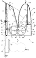
- the device of the invention is indicated as a whole with reference numeral 10 and substantially comprises a fixed assembly 20 and a movable assembly 28 comprising a sliding frame 30 and an oscillating frame 40.
- the fixed or stationary assembly comprises a vertical wall 21 provided with a guide slot extending prevalently vertically, 22. From the wall 21 there extend vertical rack means, indicated as a whole by 23, generally in the form of two rack portions 23', 23'' ( Figure 4) spaced apart from each other and parallel. Further guide slots 22' can be provided spaced apart from the slot 22 on the wall 20; wall 20 can have a flat shape or be U-shaped in a plan view.
- the sliding frame 30 is generally (but not necessarily) vertically sliding, and essentially comprises a wall 31 that defines an inner chamber 32 and has a slanting collar part 33 at the top; in the upper part, on the left in Figure 3, this forms a pivot 34 that defines a horizontal axis x. From the wall 31 there protrude one or more pins 35 slidably received for guiding engagement in the slot or slots 22.
- An elastic return means 50 supports the vertically sliding frame 30 to its resting position, shown in Figure 3.
- the elastic return means 50 in the exemplary embodiment, has been conceived as a bar of elastic rubber or rubber-like material, constrained at the ends (not shown) in the fixed frame.
- the sliding frame 30 rests on said bar and is held thereon with a lower edge thereof.
- the sliding frame 30 can be made in one piece or in two pieces constrained to each other.
- the oscillating frame 40 is made with a horizontally extending funnel-shaped structure 42, which ends with a lower mouth 42' in the form of an elongated slot.
- the funnel-shaped structure 42 ends on one side with an appendix 43 hinged on pivot 34 and on the other side has a curved operating handgrip or handle part, indicated by reference numeral 44.
- the oscillating frame carries, by means of the bracket 45, a pair of blade rollers rotating in opposite directions, indicated as a whole by 46 and respectively by 46a, 46b, enclosed in a shell 47 formed by upper and lower half-shells 47', 47''.
- the rollers 46a, 46b rotating in opposite directions have respective horizontal axes a , b , and peripheral cooperating blades referenced 48a, 48b.
- rollers have sprocket wheel parts respectively referenced 49'a, 49''a (on roller 46a) and 49'b, 49''b (on roller 46b) the teeth of which mesh with each other and with the teeth of the aforementioned racks 23', 23''.
- an elastic return means in the form of a steel spiral spring 52, applied to the shell 47, which presses the oscillating frame toward the resting position, with the sprocket wheels disengaged from the rack.
- the fixed frame 20 can be a wall of a waste basket, or it can be a rigid panel to which a waste bag can be connected.
- the sliding frame 30 In at a rest condition, which is shown with a continuous line in Figure 3, the sliding frame 30 is in its uppermost position and the oscillating frame is in its furthest position from the wall 31 of the frame 30.
- the sprocket wheels 49'a, 49''a are spaced from the sections 23', 23'' of the rack.
- the applied force causes an oscillation of the oscillating frame 40 around pivot 34 - x axis - through a small angle (clockwise in Figure 3) until the edge 44'' of the wall 44 is engaged against an opposite edge (not visible) of the vertically sliding frame 30.
- the oscillation of the oscillating frame in a clockwise direction in Figure 3 then moves the rollers rotating in opposite directions slightly towards the left in said figure (position shown in dash-dot lines in Figure 3) against the action of the spring 52, so that the teeth of the gears 49'a and 49''a are on the vertical of the teeth of the rack 23.
- shredder device referenced 110
- the parts of the device 110 that are similar to the corresponding parts of the device 10 bear the same reference numerals and will not be described in detail.
- the device 110 substantially differs from the preceding one in that the elastic return means 150 comprises one or more portions of elastic material 150a, 150b, external to the wall 21, and each extending between a pin 151a (respectively 151b etc.) integral with the sliding frame 130, and a pin 153a (respectively 153b etc.), integral with the wall 21 of the first assembly or fixed assembly 20.
- the pins 151a and 151b preferably slide within the guide slots 22 provided for the pins 35.
- the pins 35 can preferably be eliminated, since the pins 151 can have a guiding function.
- the waste container 100 which also forms a subject matter of this application, incorporates the shredding device 110 (or 10) in a first section 102 thereof and comprises a second section 104 designed to receive a removable bag S (drawn in dashlines).
- the container 100 is fit to easy separate collection of waste, in that it collects paper in section 102 and other waste in section 104; in addition, it can contain a large amount of paper, since this occupies little space when cut. Furthermore, each time the shredder device 110 is pressed, the cut paper is compressed, increasing the capacity of the paper collection section 102.
- the container 100 can be made and packed with the two parts 102 and 104 separate, equipped with coupling means for reciprocal engagement, so as to be of limited size for storage and transportation.
- guides with a particular shape are provided for cooperation between the oscillating frame and the fixed frame, so that the lowering or working stroke of the sliding frame-oscillating frame assembly follows a course that causes engagement between gears and rack, whilst the return or raising stroke keeps the sprocket wheels at a distance from the rack.
- the device of the invention enables documents to be shredded without recourse to external power sources, is simple and safe to use because the cutting parts cannot be accessed accidentally, and moreover it can be produced entirely or almost entirely in molded plastic, which allows it to be produced at limited cost.
- the device also allows the waste to be separated and the volume of paper to be compressed.
Landscapes
- Engineering & Computer Science (AREA)
- Food Science & Technology (AREA)
- Crushing And Pulverization Processes (AREA)
Applications Claiming Priority (2)
| Application Number | Priority Date | Filing Date | Title |
|---|---|---|---|
| ITMI972891 | 1997-12-30 | ||
| ITMI972891 IT1297031B1 (it) | 1997-12-30 | 1997-12-30 | Dispositivo manuale per triturare documenti |
Publications (1)
| Publication Number | Publication Date |
|---|---|
| EP0928633A1 true EP0928633A1 (de) | 1999-07-14 |
Family
ID=11378470
Family Applications (1)
| Application Number | Title | Priority Date | Filing Date |
|---|---|---|---|
| EP98111408A Withdrawn EP0928633A1 (de) | 1997-12-30 | 1998-06-22 | Handbetriebener Aktenvernichter und damit ausgerüsteter Papierkorb |
Country Status (4)
| Country | Link |
|---|---|
| EP (1) | EP0928633A1 (de) |
| AU (1) | AU8628898A (de) |
| IT (1) | IT1297031B1 (de) |
| WO (1) | WO1999034924A1 (de) |
Cited By (3)
| Publication number | Priority date | Publication date | Assignee | Title |
|---|---|---|---|---|
| DE10023284A1 (de) * | 2000-05-12 | 2001-11-29 | Fremmer Hans Kilian | Kammersystem (Aktenvernichter Kammersystem) |
| GB2439932A (en) * | 2006-07-10 | 2008-01-16 | Benjamin Bhatti | A combined dustbin and paper shredder |
| WO2016070948A1 (de) | 2014-11-07 | 2016-05-12 | Akten-Ex Gmbh & Co Kg | Vernichtung von beschriftetem papier |
Citations (5)
| Publication number | Priority date | Publication date | Assignee | Title |
|---|---|---|---|---|
| EP0010681A1 (de) * | 1978-10-19 | 1980-05-14 | Günter Trautmann | Vorrichtung zum Zerschneiden oder Zerkleinern von Papier, Karton, Mikrofilmen od. dgl |
| GB2096919A (en) * | 1981-03-11 | 1982-10-27 | Matsushita Electric Industrial Co Ltd | Shredder |
| DE8908903U1 (de) * | 1989-07-21 | 1989-10-26 | Skiera, Werner, 6909 Walldorf | Mini-Papierzerkleinerer |
| US5139205A (en) * | 1991-07-12 | 1992-08-18 | Denis Gallagher | Segregated waste disposal system |
| DE29520358U1 (de) * | 1995-12-22 | 1996-03-07 | Günther, Stefan, Dipl.-Ing., 46284 Dorsten | Aktenvernichter |
-
1997
- 1997-12-30 IT ITMI972891 patent/IT1297031B1/it active IP Right Grant
-
1998
- 1998-06-22 EP EP98111408A patent/EP0928633A1/de not_active Withdrawn
- 1998-06-22 WO PCT/EP1998/003789 patent/WO1999034924A1/en not_active Ceased
- 1998-06-22 AU AU86288/98A patent/AU8628898A/en not_active Abandoned
Patent Citations (5)
| Publication number | Priority date | Publication date | Assignee | Title |
|---|---|---|---|---|
| EP0010681A1 (de) * | 1978-10-19 | 1980-05-14 | Günter Trautmann | Vorrichtung zum Zerschneiden oder Zerkleinern von Papier, Karton, Mikrofilmen od. dgl |
| GB2096919A (en) * | 1981-03-11 | 1982-10-27 | Matsushita Electric Industrial Co Ltd | Shredder |
| DE8908903U1 (de) * | 1989-07-21 | 1989-10-26 | Skiera, Werner, 6909 Walldorf | Mini-Papierzerkleinerer |
| US5139205A (en) * | 1991-07-12 | 1992-08-18 | Denis Gallagher | Segregated waste disposal system |
| DE29520358U1 (de) * | 1995-12-22 | 1996-03-07 | Günther, Stefan, Dipl.-Ing., 46284 Dorsten | Aktenvernichter |
Cited By (6)
| Publication number | Priority date | Publication date | Assignee | Title |
|---|---|---|---|---|
| DE10023284A1 (de) * | 2000-05-12 | 2001-11-29 | Fremmer Hans Kilian | Kammersystem (Aktenvernichter Kammersystem) |
| GB2439932A (en) * | 2006-07-10 | 2008-01-16 | Benjamin Bhatti | A combined dustbin and paper shredder |
| WO2016070948A1 (de) | 2014-11-07 | 2016-05-12 | Akten-Ex Gmbh & Co Kg | Vernichtung von beschriftetem papier |
| DE202015009629U1 (de) | 2014-11-07 | 2018-11-15 | Akten-Ex Gmbh & Co. Kg | Anlage zur Aktenvernichtung |
| DE202015009627U1 (de) | 2014-11-07 | 2018-11-15 | Akten-Ex Gmbh & Co. Kg | Papier aus einer Aktenvernichtung |
| DE202015009626U1 (de) | 2014-11-07 | 2018-11-15 | Akten-Ex Gmbh & Co. Kg | Aktenvernichter |
Also Published As
| Publication number | Publication date |
|---|---|
| WO1999034924A1 (en) | 1999-07-15 |
| ITMI972891A1 (it) | 1999-06-30 |
| AU8628898A (en) | 1999-07-26 |
| IT1297031B1 (it) | 1999-08-03 |
Similar Documents
| Publication | Publication Date | Title |
|---|---|---|
| GB2427838A (en) | A shredder including a compactor plate that forms part of a waste bag support mechanism | |
| EP0928633A1 (de) | Handbetriebener Aktenvernichter und damit ausgerüsteter Papierkorb | |
| CN1131918A (zh) | 粉碎材料的设备及其方法 | |
| US5125333A (en) | Device for crushing cans and cutting plastic containers | |
| KR102370075B1 (ko) | Pet병 파쇄수단이 구비된 분리수거함 | |
| CN216230264U (zh) | 一种用于亚克力板的废料处理装置 | |
| CN114177978B (zh) | 一种环保回收废纸粉碎设备 | |
| CN213791835U (zh) | 一种粗大垃圾处理机 | |
| CN215743951U (zh) | 双轴撕碎机 | |
| CN215243231U (zh) | 一种塑料包装袋加工用剪切装置 | |
| CN210207080U (zh) | 一种带碎纸功能的安全切纸刀 | |
| JPH08266924A (ja) | 帯状廃棄物を捕捉して処理する方法及び装置 | |
| CN115245949A (zh) | 面料加工边角料回收装置 | |
| CN114192550A (zh) | 一种基于节能环保的泡沫回收用压缩装置 | |
| CN108855462B (zh) | 一种厨用粉碎器 | |
| CN2153419Y (zh) | 一次性使用医疗器具毁形机 | |
| CN202516635U (zh) | 一种能够更换刀棒组的碎纸机 | |
| CN219381220U (zh) | 一种地板面层膜废料回收粉碎装置 | |
| CN209987021U (zh) | 一种肉制品加工用切丝机 | |
| CN216609128U (zh) | 一种印刷用纸张裁剪装置 | |
| CN112189880A (zh) | 一种烟草加工用烟叶切丝设备 | |
| JPH11114882A (ja) | 樹脂容器潰し機 | |
| CN214811245U (zh) | 一种小型碎屑机 | |
| CN218313880U (zh) | 一种药物切片设备 | |
| CN209753040U (zh) | 一种基于财务会计用辅助装置 |
Legal Events
| Date | Code | Title | Description |
|---|---|---|---|
| PUAI | Public reference made under article 153(3) epc to a published international application that has entered the european phase |
Free format text: ORIGINAL CODE: 0009012 |
|
| AK | Designated contracting states |
Kind code of ref document: A1 Designated state(s): AT BE CH CY DE DK ES FI FR GB GR IE IT LI LU MC NL PT SE |
|
| AX | Request for extension of the european patent |
Free format text: AL;LT;LV;MK;RO;SI |
|
| AKX | Designation fees paid | ||
| REG | Reference to a national code |
Ref country code: DE Ref legal event code: 8566 |
|
| STAA | Information on the status of an ep patent application or granted ep patent |
Free format text: STATUS: THE APPLICATION IS DEEMED TO BE WITHDRAWN |
|
| 18D | Application deemed to be withdrawn |
Effective date: 20000115 |