EP0928740A1 - Bremsvorrichtung für einen Satz Flugzeugräder - Google Patents
Bremsvorrichtung für einen Satz Flugzeugräder Download PDFInfo
- Publication number
- EP0928740A1 EP0928740A1 EP98403330A EP98403330A EP0928740A1 EP 0928740 A1 EP0928740 A1 EP 0928740A1 EP 98403330 A EP98403330 A EP 98403330A EP 98403330 A EP98403330 A EP 98403330A EP 0928740 A1 EP0928740 A1 EP 0928740A1
- Authority
- EP
- European Patent Office
- Prior art keywords
- circuit
- valves
- brake
- hydraulic
- pressure
- Prior art date
- Legal status (The legal status is an assumption and is not a legal conclusion. Google has not performed a legal analysis and makes no representation as to the accuracy of the status listed.)
- Granted
Links
- 230000015556 catabolic process Effects 0.000 claims description 4
- 230000008901 benefit Effects 0.000 description 8
- 238000010586 diagram Methods 0.000 description 2
- 239000012530 fluid Substances 0.000 description 2
- 210000000056 organ Anatomy 0.000 description 2
- 230000035945 sensitivity Effects 0.000 description 2
- 238000010276 construction Methods 0.000 description 1
- 239000006185 dispersion Substances 0.000 description 1
- 238000006073 displacement reaction Methods 0.000 description 1
- 230000000694 effects Effects 0.000 description 1
- 238000005516 engineering process Methods 0.000 description 1
- 230000010354 integration Effects 0.000 description 1
- 238000000034 method Methods 0.000 description 1
- 230000000737 periodic effect Effects 0.000 description 1
- 238000005096 rolling process Methods 0.000 description 1
- 230000003068 static effect Effects 0.000 description 1
- 239000000725 suspension Substances 0.000 description 1
- 238000011144 upstream manufacturing Methods 0.000 description 1
Images

Classifications
-
- B—PERFORMING OPERATIONS; TRANSPORTING
- B60—VEHICLES IN GENERAL
- B60T—VEHICLE BRAKE CONTROL SYSTEMS OR PARTS THEREOF; BRAKE CONTROL SYSTEMS OR PARTS THEREOF, IN GENERAL; ARRANGEMENT OF BRAKING ELEMENTS ON VEHICLES IN GENERAL; PORTABLE DEVICES FOR PREVENTING UNWANTED MOVEMENT OF VEHICLES; VEHICLE MODIFICATIONS TO FACILITATE COOLING OF BRAKES
- B60T8/00—Arrangements for adjusting wheel-braking force to meet varying vehicular or ground-surface conditions, e.g. limiting or varying distribution of braking force
-
- B—PERFORMING OPERATIONS; TRANSPORTING
- B60—VEHICLES IN GENERAL
- B60T—VEHICLE BRAKE CONTROL SYSTEMS OR PARTS THEREOF; BRAKE CONTROL SYSTEMS OR PARTS THEREOF, IN GENERAL; ARRANGEMENT OF BRAKING ELEMENTS ON VEHICLES IN GENERAL; PORTABLE DEVICES FOR PREVENTING UNWANTED MOVEMENT OF VEHICLES; VEHICLE MODIFICATIONS TO FACILITATE COOLING OF BRAKES
- B60T13/00—Transmitting braking action from initiating means to ultimate brake actuator with power assistance or drive; Brake systems incorporating such transmitting means, e.g. air-pressure brake systems
- B60T13/10—Transmitting braking action from initiating means to ultimate brake actuator with power assistance or drive; Brake systems incorporating such transmitting means, e.g. air-pressure brake systems with fluid assistance, drive, or release
- B60T13/66—Electrical control in fluid-pressure brake systems
- B60T13/68—Electrical control in fluid-pressure brake systems by electrically-controlled valves
- B60T13/686—Electrical control in fluid-pressure brake systems by electrically-controlled valves in hydraulic systems or parts thereof
-
- B—PERFORMING OPERATIONS; TRANSPORTING
- B60—VEHICLES IN GENERAL
- B60T—VEHICLE BRAKE CONTROL SYSTEMS OR PARTS THEREOF; BRAKE CONTROL SYSTEMS OR PARTS THEREOF, IN GENERAL; ARRANGEMENT OF BRAKING ELEMENTS ON VEHICLES IN GENERAL; PORTABLE DEVICES FOR PREVENTING UNWANTED MOVEMENT OF VEHICLES; VEHICLE MODIFICATIONS TO FACILITATE COOLING OF BRAKES
- B60T17/00—Component parts, details, or accessories of power brake systems not covered by groups B60T8/00, B60T13/00 or B60T15/00, or presenting other characteristic features
- B60T17/18—Safety devices; Monitoring
-
- B—PERFORMING OPERATIONS; TRANSPORTING
- B64—AIRCRAFT; AVIATION; COSMONAUTICS
- B64C—AEROPLANES; HELICOPTERS
- B64C25/00—Alighting gear
- B64C25/32—Alighting gear characterised by elements which contact the ground or similar surface
- B64C25/42—Arrangement or adaptation of brakes
Definitions
- the present invention relates to braking controlled from an aircraft wheel train, and more particularly a braking device of a wheel set including the wheels are generally divided into two groups arranged symmetrically on either side of a longitudinal plane median of the aircraft, of the type in which each wheel is equipped with a brake actuated from brake pedals.
- the different braking devices described in the aforementioned documents thus include servovalves electrically operated, the structure of which comprises systematically two hydraulic stages interconnected by a hydraulic connection and respectively associated with the control and distribution, the control stage acting on the drawer of the distribution stage.
- the hydraulic stage control is electrically controlled, and the pressure supply valve at the servovalve is modulated level of the distribution stage by sections of passage (sprinklers) operating on a leak principle hydraulic in general of the order of one liter per minute.
- These hydraulic leaks are always necessary in a such design, and their importance makes it difficult the use of such servovalves when the source hydraulic consists of a hydraulic accumulator, which may be the case for the emergency circuit. Indeed, the volume of fluid consumed by the permanent leakage of these servovalves is no longer available to supply the brakes, which considerably limits the duration and number of braking applications before the accumulator is not empty.
- the operating pressure recovered at the outlet of the servovalve and which is a function of the intensity of the current setpoint is indeed obtained with precision poor.
- the mechanical adjustment of the servovalve at the sprinkler level does not allow obtaining a dispersion on operating pressure less than a few bars, or even around ten bars in certain points, taking into account the phenomena of non-linearity and hysteresis specific to any hydraulic device.
- the servovalve is sensitive to fluctuations in the supply pressure and fluid temperature hydraulic, which can induce pressure variations use of several bars, even in use normal.
- the mechanical wear of the nozzles induces a inevitable drift over time.
- the invention aims precisely to solve this problem, and to design a more braking device efficient, being less sensitive to the phenomena of temperature and wear, and to supply fluctuations, while remaining very precise for the operating pressure without the need to make adjustments binding periodicals.
- the object of the invention is therefore to produce a braking device of an aircraft wheel set including the structure provides precise braking and constant over time, without the aforementioned drawbacks inherent in the use of two-way brake servo valves hydraulic stages.
- a wheel train braking device aircraft each wheel of which is fitted with an actuated brake from brake pedals, said braking with two pressure sources supplying each a hydraulic circuit, including a normal circuit and an emergency circuit intervening in the event of a breakdown, these two hydraulic circuits leading to each of the different brakes via an associated brake valve, the brake valves of the normal circuit and / or the backup circuit being constituted by direct drive valves controlled electrically by an electronic control unit associated.
- Direct drive, or “direct” valves drive valve “(DDV) for Anglo-Saxons are, so surprising for the skilled person, very efficient in as part of an integrated use with aircraft braking.
- Such direct drive valves have so far only been used in machine tools for position or displacement controls (for example in rolling mills), or in suspensions of motor vehicles.
- position or displacement controls for example in rolling mills
- suspensions of motor vehicles In the known uses of such direct drive valves it was generally provided for flow control (not pressure), that the position of the valve distributor is controlled by a position sensor.
- the valves braking of the emergency circuit are only constituted by direct drive valves, the brake valves of the normal circuit being servovalves of the type traditional.
- the brake valves of the normal circuit being servovalves of the type traditional.
- the brake valves of the normal circuit and the emergency circuit are all formed by drive valves direct. We then have many advantages which will be detailed later, inherent in the use of direct drive for the entire braking circuit, so both for normal use and use in case of failure.
- At least some of the direct drive valves are pressure controlled.
- each drive valve direct pressure controlled includes a hydraulic distributor and an electric actuation motor controlled by associated control electronics, and on the output use of the hydraulic distributor, a pressure which sends said control electronics a electrical signal representative of the pressure measured.
- the direct drive valve pressure-controlled can also be controlled by position thanks to a position sensor associated with the motor electrical actuation, which sends an electrical signal corresponding to the associated control electronics.
- the valve with direct drive not comprising the first hydraulic stage of traditional servovalves (for example a quadruple hydraulic potentiometer), the power to control the valve distributor is now electric (it is indeed only the distributor actuator motor control) and not more hydraulic (by the leakage of the first hydraulic stage servovalve).
- the leakage of the drive valve direct is now circumscribed to the distributor of this valve, and therefore by construction lower than the leakage of a traditional servovalve.
- a parking brake circuit is combined with the circuit backup with a common power supply, said circuit braking park leading to each of the wheel brakes by a associated shuttle valve located downstream of the corresponding direct training.
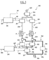
- Figure 1 illustrates a braking device of an aircraft wheel set, and it has been illustrated, by way of example, a set of two pairs of wheels R, one of which pair is to the left and the other to the right of the aircraft.
- the brakes rated F on each wheel are actuated from brake pedals not shown here.
- each wheel is here equipped with a T speedometer addressing each an information to the electronic organs of control in relation to the speed of the wheel concerned.
- the braking device rated 100 has two pressure sources each supplying a hydraulic circuit.
- a so-called normal hydraulic circuit is thus distinguished 101, and a hydraulic circuit called emergency 102, which intervenes in the event of a breakdown.
- the normal circuit 101 is arranged in accordance with a traditional technique, in particular by comprising associated brake servovalves 109 each with a wheel brake. We will therefore only recall briefly the different components of this hydraulic circuit 101.
- the circuit entry marked 103 leads to a solenoid valve 104, downstream of which there is a branch 105 equipped with a pressure sensor 106.
- Branch 105 leads to a common branch 107 supplying parallel branches 108 in number equal to that of the number of wheels concerned (here four).
- Each branch 108 has successively a double-stage hydraulic servovalve of traditional type 109, downstream of which there is a hydraulic fuse 110, and a connection for a pressure 111.
- the backup circuit 102 includes a hydraulic source which is here constituted by an accumulator hydraulic.
- This backup circuit 102 includes more precisely an inlet 112 leading to a non-return valve 113, downstream of which there is a first branch 114 equipped with an accumulator 115 and a pressure sensor 116, and leading to a solenoid valve 117 which is analogous to the above-mentioned solenoid valve 104.
- the other branch 119 leads to her a park solenoid valve 122, downstream of which there is a branch 123 leading to the entrance of two valves shuttles 121, downstream of which there is a fuse hydraulic 124 and a pressure sensor 125, front to arrive by a branch 128 at brake F of each of wheels.
- valves 150 which, in accordance with a feature of the invention, are valves with direct drive (or "direct drive valve”, or DDV).
- DDV direct drive valve
- Each of these direct drive valves 150 is electrically controlled by an electronic unit of associated command denoted 120 (here common to the two valves), by means of connections denoted 127.
- each direct drive valve 150 is preferably fitted control electronics, internal to said valve, which provides pressure control of the drive valve direct and receives unit pressure commands associated control electronics 120.
- Use output hydraulic of each of these valves 150 is noted 126, and leads to the other entry of the aforementioned shuttle valves 121.
- the brake valves of the circuit emergency 102 are constituted by valves with drive direct (here two valves 150), while the valves of braking of the normal circuit 101 are servovalves 109 of traditional type.
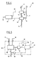
- Figure 4 shows part of the hydraulic circuit brake rated 10, with a supply line 11 arriving on a solenoid valve 12.
- the outlet use of the solenoid valve, noted 13, leads to a valve direct drive 50, the return output of this same solenoid valve 12 being noted 15.
- the use output of the valve 50 with direct drive is noted 14 and leads to the brake (s) concerned, while the return output denoted 16 of said valve joins a line 17 common to the output 15 of return of the solenoid valve 12.
- a electronic control unit 20 receives orders pilot-controlled brake systems, such as symbolized by the arrow 18. This electronic unit of command 20 can thus send an opening order to the upstream solenoid valve 12, as symbolized by line 19, as well as a pressure command to the drive valve direct 50 (or more exactly to the control electronics internal to this valve), as symbolized by line 21.
- FIG. 5 provides a better understanding of the layout of the aforementioned direct drive valve 50.
- the valve 50 is here diagrammed by a rectangle in lines mixed, and essentially includes a distributor hydraulic 30 and an electric actuating motor 31 which is connected to this distributor by a mechanical link 32.
- the mechanical connection 32 is shown here so schematic, but we can easily understand that this type of link includes any type of conventional mechanical device able to transform a rotational movement into a linear movement, a rotational movement into another rotational movement, or linear movement in another linear movement, thus acting as appropriate on the sliding drawer or rotating distributor valve hydraulic 30.
- the distributor 30 is connected to the power supply high pressure hydraulics 13, at the outlet of use 14, and at the low pressure return output 16 all shown in Figure 4.
- the distributor 30 is the only hydraulic stage of the direct drive valve 50, unlike traditional servovalves which include two hydraulic stages.
- the drive valve direct 50 also includes control electronics denoted 37, internal to said valve, which receives orders from pressure delivered by the control unit 20 via the line 21 shown in FIG. 4.
- the hydraulic motor actuation 31 is thus controlled by the electronics of associated electronic control 37, as shown schematically by the arrow 38.
- valve with drive direct 50 is controlled by pressure, the control by pressure provided by the control electronics associated internal.
- the direct drive valve 50 thus additionally comprises a pressure sensor 33 stitched on the use pipe 14 of the distributor 30, which sensor sends an electrical signal representative of the pressure measured at control electronics 37, as shown schematically by line 34. So the electrical order sent by control electronics 37 to the electric motor 31 takes into account at all times the operating pressure measured by the pressure sensor 33.
- This pressure sensor 33 which consumes little energy, can provide very high accuracy, in the range of bar over the entire range of use (we know that the servovalves show an error of up to about ten bars at certain points on the beach of use).
- the pressure sensor 33 may furthermore have an integrated temperature correction device so as to remove any harmful influence or sensitivity to temperature (remember that traditional servovalves are extremely sensitive to temperature, this influence being of the order of a few bars per ten degrees Celsius).
- the direct drive valve 50 is also much less sensitive to fluctuations than traditional servovalves with two hydraulic stages, thanks to the pressure produced by the pressure sensor 33. In the case where the pressure sensor 33 is provided, this sensor is downstream of the distributor, which is in favor insensitivity to pressure variations.
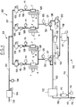
- Circuit 200 illustrated in FIG. 2 comprises a normal circuit 201, and an emergency circuit 202.
- a pipe supply 203 leading to a solenoid valve 204, downstream of which a common branch 205 supplies two pipelines 206 equipped on one hand with a servovalve 207 and on the other hand a pressure sensor 208.
- the orders pilot-controlled braking systems symbolized by line 209, arrive at an electronic unit of normal circuit 210 command.
- Command commands addressed to the solenoid valve 204 on the one hand and to the servovalves 207 on the other hand, are respectively symbolized by the lines 211 and 212.
- the electronic control unit 210 also receives electrical signals from two pressure sensors 208, as shown schematically by the lines 213.
- an electronic control unit for the emergency circuit 220 receiving electrical commands from braking controlled by the pilot, as shown schematically by the line 224, and issuing pressure orders to each of the two direct drive valves 250 of the circuit relief.
- the backup circuit 202 has an input supply 214 leading to a common branch 215 which feeds two branches 216 and 217.
- Branch 217 includes a solenoid valve 219 which receives electrical signals from control of the electronic control unit 220, as shown schematically by line 226. Downstream of the solenoid valve 219, there is a common branch 221 serving two branches 222 each equipped with a direct drive valve 250, then, downstream thereof, a shuttle valve 223.
- the direct drive valves 250 receive an order control unit 220, as shown by lines 227.
- Figure 3 illustrates another variant of the braking device of the invention, which is fairly close of the one just described with reference to the figure 2.
- the main difference compared to circuit 200 previously described lies in the replacement, in the normal circuit, traditional type 207 servovalves by direct drive brake valves 351 similar to the valves marked 350 already provided for the emergency circuit 302.
- the circuit 300 of FIG. 3 has a normal 301 circuit also fitted with valves direct drive 351.
- the other components illustrated in figure 3 correspond exactly to those of circuit 200 illustrated in Figure 2, and the same references are used increased by 100 for homologous components, which will therefore not be described again.
- the brake valves of the normal circuit 301 and emergency circuit 302 are therefore all consisting of direct drive valves, 351 and 350 respectively. This results in braking electric taking full advantage of the replacement of traditional two-stage hydraulic servovalves by direct drive valves as above described.
- a second servo loop to have additional control, like illustrated in FIG. 5: in fact, a servo-control is produced internal in position, thanks to a position sensor 35 associated with the electric actuating motor 31, which sends an electrical signal corresponding to the electronics associated command 37, as shown by line 36, this additional control loop being represented in mixed lines to better show his optional character.
- this second position control loop does not not from the electric motor 31, but from the distributor 30, to send a corresponding electrical signal to the control electronics 37.
- the additional control means obtained through this second servo loop further improves accuracy and dynamic response.
- direct drive valves having no first hydraulic stage unlike traditional servovalves (for example of the potentiometer type hydraulic quadruple), the power to control the valve distributor is electric (this is the motor control) and no longer hydraulic (leakage from first floor).
- the very low leakage from the drive valve direct limited to the distributor thereof, considerably facilitates the choice of a braking mode electric on a supply circuit limited in volume (for example constituted by a hydraulic accumulator).
Landscapes
- Engineering & Computer Science (AREA)
- Mechanical Engineering (AREA)
- Transportation (AREA)
- Aviation & Aerospace Engineering (AREA)
- Regulating Braking Force (AREA)
- Valves And Accessory Devices For Braking Systems (AREA)
- Braking Systems And Boosters (AREA)
Applications Claiming Priority (2)
| Application Number | Priority Date | Filing Date | Title |
|---|---|---|---|
| FR9800197A FR2773530B1 (fr) | 1998-01-12 | 1998-01-12 | Dispositif de freinage d'un train de roues d'aeronef |
| FR9800197 | 1998-01-12 |
Publications (2)
| Publication Number | Publication Date |
|---|---|
| EP0928740A1 true EP0928740A1 (de) | 1999-07-14 |
| EP0928740B1 EP0928740B1 (de) | 2004-09-01 |
Family
ID=9521656
Family Applications (1)
| Application Number | Title | Priority Date | Filing Date |
|---|---|---|---|
| EP98403330A Expired - Lifetime EP0928740B1 (de) | 1998-01-12 | 1998-12-30 | Bremsvorrichtung für einen Satz Flugzeugräder |
Country Status (7)
| Country | Link |
|---|---|
| US (1) | US6193326B1 (de) |
| EP (1) | EP0928740B1 (de) |
| JP (1) | JP4260959B2 (de) |
| CA (1) | CA2259106C (de) |
| DE (1) | DE69825963T2 (de) |
| ES (1) | ES2227789T3 (de) |
| FR (1) | FR2773530B1 (de) |
Cited By (7)
| Publication number | Priority date | Publication date | Assignee | Title |
|---|---|---|---|---|
| US6193326B1 (en) * | 1998-01-12 | 2001-02-27 | Messier-Bugatti | Apparatus for braking a set of aircraft wheels |
| EP0980807A3 (de) * | 1998-08-15 | 2003-03-19 | Dunlop Aerospace Limited | Bremssystem |
| FR2915157A1 (fr) * | 2007-04-18 | 2008-10-24 | Beringer Sa Sa | Dispositif de freinage de securite monte entre un reservoir de fluide hydraulique et des organes actionneurs aptes a agir sur des elements de freinage. |
| FR2955817A1 (fr) * | 2010-02-03 | 2011-08-05 | Messier Bugatti | Architecture de freinage hydraulique pour aeronef avec freins a demi-cavites |
| CN102328750A (zh) * | 2010-06-10 | 2012-01-25 | 梅西耶-布加蒂公司 | 配装有独立驱动装置的飞机 |
| EP3418135A1 (de) * | 2017-06-21 | 2018-12-26 | Airbus Operations Limited | Steuerung von fahrzeugbremsen |
| FR3153596A1 (fr) * | 2023-09-28 | 2025-04-04 | Safran Landing Systems | Circuit de freinage simplifié pour aéronef |
Families Citing this family (20)
| Publication number | Priority date | Publication date | Assignee | Title |
|---|---|---|---|---|
| US6390571B1 (en) * | 2000-06-29 | 2002-05-21 | Goodrich Corporation | Redundant aircraft braking system architecture |
| FR2816583B1 (fr) * | 2000-11-10 | 2003-02-21 | Messier Bugatti | Architecture de systeme hydraulique de freinage d'aeronef |
| US6672688B2 (en) | 2001-05-22 | 2004-01-06 | Honeywell International Inc. | Anti-lock braking system module for aircraft equipped with master cylinder brake systems |
| US6826909B2 (en) * | 2001-11-08 | 2004-12-07 | Parker-Hannifin Corp. | Hydraulic gerotor motor with integral shuttle valve |
| DE10222123A1 (de) * | 2002-05-17 | 2003-11-27 | Aircabin Gmbh | Absenkbares Gepäckfach mit Gasdruckfederverriegelung |
| AT412916B (de) * | 2002-07-19 | 2005-08-25 | Avl List Gmbh | Verfahren zur simulation des fahrverhaltens von fahrzeugen |
| WO2009089551A2 (en) * | 2008-01-11 | 2009-07-16 | General Atomics | Braking system with linear actuator |
| US20110187180A1 (en) * | 2010-02-03 | 2011-08-04 | Messier-Bugatti | Hydraulic braking architecture for aircraft having brakes with half-cavities |
| US9669810B2 (en) | 2012-01-10 | 2017-06-06 | Honeywell International Inc. | Brake assembly including independently activatable brake actuators |
| DE102012020818A1 (de) * | 2012-10-23 | 2014-04-24 | Liebherr-Hydraulikbagger Gmbh | Bremsvorrichtung für Arbeitsmaschinen und Verfahren zum Betätigen der Bremsvorrichtung |
| US9650130B2 (en) * | 2014-03-24 | 2017-05-16 | Mohammed Bouzmane | Electric hydraulic motor system for aircraft |
| US10259571B2 (en) | 2016-12-06 | 2019-04-16 | Goodrich Corporation | Electrically controlled park and emergency valve assembly |
| US10093296B2 (en) * | 2017-01-25 | 2018-10-09 | Goodrich Corporation | Electrically activated park and emergency valve with on-valve manual actuation feature |
| US10093291B2 (en) | 2017-02-02 | 2018-10-09 | Goodrich Corporation | Hydraulic park brake system and method |
| DE102018205957A1 (de) * | 2017-05-18 | 2018-11-22 | Robert Bosch Gmbh | Elektronisch druckregelbare Bremsanlage und Verfahren zur Steuerung einer elektronisch druckregelbaren Bremsanlage |
| CN107472230B (zh) * | 2017-08-23 | 2023-07-07 | 徐工集团工程机械股份有限公司 | 一种液压驱动压路机制动系统 |
| CN108284947B (zh) * | 2017-12-13 | 2021-11-02 | 中航(成都)无人机系统股份有限公司 | 一种基于蓄压储能的飞机刹车系统 |
| FR3082503B1 (fr) * | 2018-06-14 | 2020-09-04 | Safran Landing Systems | Procede de freinage secours d'un aeronef |
| CN112572392B (zh) * | 2019-09-30 | 2022-04-26 | 湖南中车智行科技有限公司 | 一种车辆制动系统及车辆制动系统控制方法 |
| CN114616176B (zh) * | 2019-10-15 | 2025-02-18 | 空中客车营运有限公司 | 将液压流体从飞行器液压系统移除的方法、飞行器液压系统和飞行器 |
Citations (5)
| Publication number | Priority date | Publication date | Assignee | Title |
|---|---|---|---|---|
| FR2038576A5 (de) * | 1969-03-19 | 1971-01-08 | Gachot Jean | |
| EP0275786A1 (de) * | 1986-12-26 | 1988-07-27 | Messier-Hispano-Bugatti | Bremskreis für Flugzeuge |
| DE3939091A1 (de) * | 1989-11-25 | 1991-05-29 | Bosch Gmbh Robert | Druckmodulator fuer eine fahrzeug-bremsanlage |
| DE4445975A1 (de) * | 1994-12-22 | 1996-06-27 | Bosch Gmbh Robert | Bremsanlage für Kraftfahrzeuge |
| DE19523108C1 (de) * | 1995-06-26 | 1996-11-14 | Daimler Benz Ag | Elektrohydraulische Bremsanlage für ein Straßenfahrzeug |
Family Cites Families (18)
| Publication number | Priority date | Publication date | Assignee | Title |
|---|---|---|---|---|
| DE1118020B (de) * | 1959-04-17 | 1961-11-23 | Karl Marx Stadt Ind Werke | Steuergeraet fuer hydraulische oder pneumatische Laufradbremsen von Flugzeugen |
| US3807810A (en) * | 1971-07-07 | 1974-04-30 | Yarber A | Brake control valve system |
| US3880475A (en) * | 1972-03-29 | 1975-04-29 | Goodyear Tire & Rubber | Anti-skid system |
| US3926479A (en) * | 1973-11-12 | 1975-12-16 | Boeing Co | Aircraft automatic braking system having auto-brake control logic |
| US5024491A (en) * | 1976-11-18 | 1991-06-18 | The Boeing Company | Automatic aircraft braking system including wheelspeed responsive control apparatus |
| US4269455A (en) * | 1978-08-14 | 1981-05-26 | Goodyear Aerospace Corporation | Antiskid brake control system |
| US4548089A (en) * | 1981-12-02 | 1985-10-22 | Pneumo Corporation | Electro-mechanical direct drive valve servo system with rotary to linear valve drive mechanism |
| FR2522602A1 (fr) * | 1982-03-05 | 1983-09-09 | Messier Hispano Sa | Dispositif pour la commande d'un systeme de freinage de vehicule notamment d'un aeronef |
| US4640475A (en) * | 1984-12-24 | 1987-02-03 | The Boeing Company | Aircraft wheel brake control system and method |
| US4792192A (en) * | 1988-02-11 | 1988-12-20 | The Boeing Company | Automatic brake source select system |
| US5020322A (en) * | 1988-11-08 | 1991-06-04 | Sundstrand Corporation | Accumulator blow-back hydraulic circuit |
| US5044697A (en) * | 1989-05-26 | 1991-09-03 | Crane Company | Brake valve control system |
| US6604708B1 (en) * | 1989-12-26 | 2003-08-12 | The Boeing Company | Carbon brake wear for aircraft |
| US5050940A (en) * | 1990-02-05 | 1991-09-24 | Allied-Signal Inc. | Brake control and anti-skid system |
| FR2701006B1 (fr) * | 1993-02-01 | 1995-03-10 | Messier Bugatti | Procédé de pilotage d'un dispositif de freinage électro-hydraulique d'un train de roues d'aéronef, et dispositif de mise en Óoeuvre dudit procédé. |
| FR2702447B1 (fr) * | 1993-03-08 | 1995-04-28 | Messier Bugatti | Dispositif de freinage électro-hydraulique d'un train de roues d'aéronef. |
| US5456523A (en) * | 1994-01-19 | 1995-10-10 | Mcdonnell Douglas Corporation | Multi-wheel brake system |
| FR2773530B1 (fr) * | 1998-01-12 | 2000-02-11 | Messier Bugatti | Dispositif de freinage d'un train de roues d'aeronef |
-
1998
- 1998-01-12 FR FR9800197A patent/FR2773530B1/fr not_active Expired - Lifetime
- 1998-12-30 DE DE69825963T patent/DE69825963T2/de not_active Expired - Lifetime
- 1998-12-30 ES ES98403330T patent/ES2227789T3/es not_active Expired - Lifetime
- 1998-12-30 EP EP98403330A patent/EP0928740B1/de not_active Expired - Lifetime
-
1999
- 1999-01-08 CA CA002259106A patent/CA2259106C/fr not_active Expired - Fee Related
- 1999-01-08 US US09/227,191 patent/US6193326B1/en not_active Expired - Lifetime
- 1999-01-11 JP JP00409999A patent/JP4260959B2/ja not_active Expired - Fee Related
Patent Citations (5)
| Publication number | Priority date | Publication date | Assignee | Title |
|---|---|---|---|---|
| FR2038576A5 (de) * | 1969-03-19 | 1971-01-08 | Gachot Jean | |
| EP0275786A1 (de) * | 1986-12-26 | 1988-07-27 | Messier-Hispano-Bugatti | Bremskreis für Flugzeuge |
| DE3939091A1 (de) * | 1989-11-25 | 1991-05-29 | Bosch Gmbh Robert | Druckmodulator fuer eine fahrzeug-bremsanlage |
| DE4445975A1 (de) * | 1994-12-22 | 1996-06-27 | Bosch Gmbh Robert | Bremsanlage für Kraftfahrzeuge |
| DE19523108C1 (de) * | 1995-06-26 | 1996-11-14 | Daimler Benz Ag | Elektrohydraulische Bremsanlage für ein Straßenfahrzeug |
Cited By (11)
| Publication number | Priority date | Publication date | Assignee | Title |
|---|---|---|---|---|
| US6193326B1 (en) * | 1998-01-12 | 2001-02-27 | Messier-Bugatti | Apparatus for braking a set of aircraft wheels |
| EP0980807A3 (de) * | 1998-08-15 | 2003-03-19 | Dunlop Aerospace Limited | Bremssystem |
| FR2915157A1 (fr) * | 2007-04-18 | 2008-10-24 | Beringer Sa Sa | Dispositif de freinage de securite monte entre un reservoir de fluide hydraulique et des organes actionneurs aptes a agir sur des elements de freinage. |
| WO2008139072A3 (fr) * | 2007-04-18 | 2008-12-31 | Beringer Sa | Dispositif de freinage de securite monte entre un reservoir de fluide hydraulique et des organes actionneurs aptes a agir sur des elements de freinage |
| FR2955817A1 (fr) * | 2010-02-03 | 2011-08-05 | Messier Bugatti | Architecture de freinage hydraulique pour aeronef avec freins a demi-cavites |
| EP2357113A1 (de) * | 2010-02-03 | 2011-08-17 | Messier-Bugatti-Dowty | Hydraulisches Bremssystem für Flugzeuge mit gleichzeitig angesteuerten Doppelkammerbremsen. |
| CN102328750A (zh) * | 2010-06-10 | 2012-01-25 | 梅西耶-布加蒂公司 | 配装有独立驱动装置的飞机 |
| CN102328750B (zh) * | 2010-06-10 | 2014-10-01 | 梅西耶-布加蒂-道提公司 | 配装有独立驱动装置的飞机 |
| EP3418135A1 (de) * | 2017-06-21 | 2018-12-26 | Airbus Operations Limited | Steuerung von fahrzeugbremsen |
| US10723331B2 (en) | 2017-06-21 | 2020-07-28 | Airbus Operations Limited | Controlling vehicle brakes |
| FR3153596A1 (fr) * | 2023-09-28 | 2025-04-04 | Safran Landing Systems | Circuit de freinage simplifié pour aéronef |
Also Published As
| Publication number | Publication date |
|---|---|
| CA2259106C (fr) | 2002-05-14 |
| DE69825963D1 (de) | 2004-10-07 |
| FR2773530B1 (fr) | 2000-02-11 |
| JPH11314599A (ja) | 1999-11-16 |
| EP0928740B1 (de) | 2004-09-01 |
| US6193326B1 (en) | 2001-02-27 |
| ES2227789T3 (es) | 2005-04-01 |
| DE69825963T2 (de) | 2005-09-15 |
| FR2773530A1 (fr) | 1999-07-16 |
| CA2259106A1 (fr) | 1999-07-12 |
| JP4260959B2 (ja) | 2009-04-30 |
Similar Documents
| Publication | Publication Date | Title |
|---|---|---|
| EP0928740B1 (de) | Bremsvorrichtung für einen Satz Flugzeugräder | |
| CA2451099C (fr) | Architecture de circuit hydraulique | |
| EP0614805B1 (de) | Elektrohydraulische Bremsvorrichtung für das Fahrwerk eines Flugzeugs | |
| EP1205369B1 (de) | Architektur eines hydraulischen Flugzeugbremssystems | |
| EP1107897B1 (de) | Bremsvorrichtung mit kombinierter regelung und verstärkung | |
| FR2538329A1 (fr) | Systeme de freinage a deux circuits avec regulation du glissement de freinage, notamment pour vehicule automobile | |
| FR2787757A1 (fr) | Systeme de direction pour vehicules automobiles | |
| FR2732652A1 (fr) | Vehicule electro-hydraulique a recuperation d'energie | |
| FR2714654A1 (fr) | Dispositif de freinage pour cycles motorisés. | |
| FR2594768A1 (fr) | Systeme hydraulique de freinage antiblocage | |
| EP0334723B1 (de) | Steuervorrichtung für einen hydraulischen doppelt wirkenden Arbeitszylinder | |
| CH627978A5 (fr) | Procede et dispositif de freinage automatique d'un vehicule, notamment d'un aeronef. | |
| FR2605570A1 (fr) | Systeme de freinage anti-blocage a regulation du glissement de traction | |
| FR2467752A1 (fr) | Systeme de freinage hydraulique | |
| FR2505757A1 (fr) | Systeme de regulation antiblocage pour roues de vehicules | |
| CA2500842C (fr) | Systeme de pilotage longitudinal d'un aeronef roulant sur le sol | |
| FR2597052A1 (fr) | Systeme hydraulique de freinage equipe d'un dispositif de regulation du glissement de roue | |
| EP1890935A1 (de) | Verfahren und vorrichtung zum antrieb eines flugzeugs während seines bodenlaufs | |
| EP3279046B1 (de) | Bremskreis, fahrzeug mit einem derartigen bremskreis und bremssteuerverfahren eines fahrzeugs. | |
| EP0410891B1 (de) | Hydraulischer Bremskreis | |
| EP0353125A1 (de) | Doppelsteuervorrichtung eines Hydraulikkreises, insbesondere für eine Bremsanlage oder eine Servolenkung eines Kraftfahrzeuges | |
| FR2752401A1 (fr) | Installation de freinage a circuits multiples pour vehicules | |
| EP1534567B1 (de) | Beschleunigungs- und bremswertgeber für kraftfahrzeuge | |
| EP1029761B1 (de) | Bremsanlage für Kraftfahrzeuge mit hydropneumatischer Radaufhängung | |
| EP0844117B1 (de) | Elektrohydraulische Niveaukorrektureinrichtung für die Karosserie eines zweiachsigen Kraftfahrzeuges |
Legal Events
| Date | Code | Title | Description |
|---|---|---|---|
| PUAI | Public reference made under article 153(3) epc to a published international application that has entered the european phase |
Free format text: ORIGINAL CODE: 0009012 |
|
| AK | Designated contracting states |
Kind code of ref document: A1 Designated state(s): DE ES GB IT |
|
| AX | Request for extension of the european patent |
Free format text: AL;LT;LV;MK;RO;SI |
|
| 17P | Request for examination filed |
Effective date: 19991213 |
|
| AKX | Designation fees paid |
Free format text: DE ES GB IT |
|
| GRAP | Despatch of communication of intention to grant a patent |
Free format text: ORIGINAL CODE: EPIDOSNIGR1 |
|
| GRAS | Grant fee paid |
Free format text: ORIGINAL CODE: EPIDOSNIGR3 |
|
| GRAA | (expected) grant |
Free format text: ORIGINAL CODE: 0009210 |
|
| AK | Designated contracting states |
Kind code of ref document: B1 Designated state(s): DE ES GB IT |
|
| REG | Reference to a national code |
Ref country code: GB Ref legal event code: FG4D Free format text: NOT ENGLISH |
|
| REF | Corresponds to: |
Ref document number: 69825963 Country of ref document: DE Date of ref document: 20041007 Kind code of ref document: P |
|
| GBT | Gb: translation of ep patent filed (gb section 77(6)(a)/1977) |
Effective date: 20041111 |
|
| REG | Reference to a national code |
Ref country code: ES Ref legal event code: FG2A Ref document number: 2227789 Country of ref document: ES Kind code of ref document: T3 |
|
| PLBE | No opposition filed within time limit |
Free format text: ORIGINAL CODE: 0009261 |
|
| STAA | Information on the status of an ep patent application or granted ep patent |
Free format text: STATUS: NO OPPOSITION FILED WITHIN TIME LIMIT |
|
| 26N | No opposition filed |
Effective date: 20050602 |
|
| PGFP | Annual fee paid to national office [announced via postgrant information from national office to epo] |
Ref country code: ES Payment date: 20111227 Year of fee payment: 14 |
|
| PGFP | Annual fee paid to national office [announced via postgrant information from national office to epo] |
Ref country code: IT Payment date: 20111227 Year of fee payment: 14 |
|
| PGFP | Annual fee paid to national office [announced via postgrant information from national office to epo] |
Ref country code: DE Payment date: 20121220 Year of fee payment: 15 |
|
| PG25 | Lapsed in a contracting state [announced via postgrant information from national office to epo] |
Ref country code: IT Free format text: LAPSE BECAUSE OF NON-PAYMENT OF DUE FEES Effective date: 20121230 |
|
| REG | Reference to a national code |
Ref country code: ES Ref legal event code: FD2A Effective date: 20140307 |
|
| PG25 | Lapsed in a contracting state [announced via postgrant information from national office to epo] |
Ref country code: ES Free format text: LAPSE BECAUSE OF NON-PAYMENT OF DUE FEES Effective date: 20121231 |
|
| REG | Reference to a national code |
Ref country code: DE Ref legal event code: R119 Ref document number: 69825963 Country of ref document: DE |
|
| REG | Reference to a national code |
Ref country code: DE Ref legal event code: R119 Ref document number: 69825963 Country of ref document: DE Effective date: 20140701 |
|
| PG25 | Lapsed in a contracting state [announced via postgrant information from national office to epo] |
Ref country code: DE Free format text: LAPSE BECAUSE OF NON-PAYMENT OF DUE FEES Effective date: 20140701 |
|
| PGFP | Annual fee paid to national office [announced via postgrant information from national office to epo] |
Ref country code: GB Payment date: 20171221 Year of fee payment: 20 |
|
| REG | Reference to a national code |
Ref country code: GB Ref legal event code: PE20 Expiry date: 20181229 |
|
| PG25 | Lapsed in a contracting state [announced via postgrant information from national office to epo] |
Ref country code: GB Free format text: LAPSE BECAUSE OF EXPIRATION OF PROTECTION Effective date: 20181229 |