EP0928763B1 - Procédé pour aligner des feuilles utilisant un seul capteur - Google Patents
Procédé pour aligner des feuilles utilisant un seul capteur Download PDFInfo
- Publication number
- EP0928763B1 EP0928763B1 EP99100204A EP99100204A EP0928763B1 EP 0928763 B1 EP0928763 B1 EP 0928763B1 EP 99100204 A EP99100204 A EP 99100204A EP 99100204 A EP99100204 A EP 99100204A EP 0928763 B1 EP0928763 B1 EP 0928763B1
- Authority
- EP
- European Patent Office
- Prior art keywords
- sheet
- registration
- single sensor
- belt
- sheets
- Prior art date
- Legal status (The legal status is an assumption and is not a legal conclusion. Google has not performed a legal analysis and makes no representation as to the accuracy of the status listed.)
- Expired - Lifetime
Links
- 238000000034 method Methods 0.000 title claims description 12
- 238000012546 transfer Methods 0.000 description 17
- 239000000843 powder Substances 0.000 description 13
- 239000000463 material Substances 0.000 description 10
- 239000002245 particle Substances 0.000 description 10
- 230000032258 transport Effects 0.000 description 7
- 239000008187 granular material Substances 0.000 description 5
- 230000008569 process Effects 0.000 description 4
- 239000003795 chemical substances by application Substances 0.000 description 3
- 238000004140 cleaning Methods 0.000 description 3
- 238000011161 development Methods 0.000 description 3
- 238000003384 imaging method Methods 0.000 description 3
- 230000007246 mechanism Effects 0.000 description 2
- 108091008695 photoreceptors Proteins 0.000 description 2
- 239000000758 substrate Substances 0.000 description 2
- 229920002799 BoPET Polymers 0.000 description 1
- BUGBHKTXTAQXES-UHFFFAOYSA-N Selenium Chemical compound [Se] BUGBHKTXTAQXES-UHFFFAOYSA-N 0.000 description 1
- RTAQQCXQSZGOHL-UHFFFAOYSA-N Titanium Chemical compound [Ti] RTAQQCXQSZGOHL-UHFFFAOYSA-N 0.000 description 1
- 230000009471 action Effects 0.000 description 1
- 230000002457 bidirectional effect Effects 0.000 description 1
- 239000011230 binding agent Substances 0.000 description 1
- 230000008859 change Effects 0.000 description 1
- 230000001276 controlling effect Effects 0.000 description 1
- 238000012937 correction Methods 0.000 description 1
- 230000001934 delay Effects 0.000 description 1
- 230000001419 dependent effect Effects 0.000 description 1
- 239000004973 liquid crystal related substance Substances 0.000 description 1
- 230000003287 optical effect Effects 0.000 description 1
- 238000012545 processing Methods 0.000 description 1
- 239000010453 quartz Substances 0.000 description 1
- 230000001105 regulatory effect Effects 0.000 description 1
- 229910052711 selenium Inorganic materials 0.000 description 1
- 239000011669 selenium Substances 0.000 description 1
- VYPSYNLAJGMNEJ-UHFFFAOYSA-N silicon dioxide Inorganic materials O=[Si]=O VYPSYNLAJGMNEJ-UHFFFAOYSA-N 0.000 description 1
- 229910052719 titanium Inorganic materials 0.000 description 1
- 239000010936 titanium Substances 0.000 description 1
- 239000002699 waste material Substances 0.000 description 1
Images


Classifications
-
- B—PERFORMING OPERATIONS; TRANSPORTING
- B65—CONVEYING; PACKING; STORING; HANDLING THIN OR FILAMENTARY MATERIAL
- B65H—HANDLING THIN OR FILAMENTARY MATERIAL, e.g. SHEETS, WEBS, CABLES
- B65H9/00—Registering, e.g. orientating, articles; Devices therefor
- B65H9/002—Registering, e.g. orientating, articles; Devices therefor changing orientation of sheet by only controlling movement of the forwarding means, i.e. without the use of stop or register wall
-
- B—PERFORMING OPERATIONS; TRANSPORTING
- B41—PRINTING; LINING MACHINES; TYPEWRITERS; STAMPS
- B41J—TYPEWRITERS; SELECTIVE PRINTING MECHANISMS, i.e. MECHANISMS PRINTING OTHERWISE THAN FROM A FORME; CORRECTION OF TYPOGRAPHICAL ERRORS
- B41J11/00—Devices or arrangements of selective printing mechanisms, e.g. ink-jet printers or thermal printers, for supporting or handling copy material in sheet or web form
- B41J11/0045—Guides for printing material
- B41J11/0055—Lateral guides, e.g. guides for preventing skewed conveyance of printing material
-
- B—PERFORMING OPERATIONS; TRANSPORTING
- B41—PRINTING; LINING MACHINES; TYPEWRITERS; STAMPS
- B41J—TYPEWRITERS; SELECTIVE PRINTING MECHANISMS, i.e. MECHANISMS PRINTING OTHERWISE THAN FROM A FORME; CORRECTION OF TYPOGRAPHICAL ERRORS
- B41J13/00—Devices or arrangements of selective printing mechanisms, e.g. ink-jet printers or thermal printers, specially adapted for supporting or handling copy material in short lengths, e.g. sheets
- B41J13/26—Registering devices
-
- G—PHYSICS
- G03—PHOTOGRAPHY; CINEMATOGRAPHY; ANALOGOUS TECHNIQUES USING WAVES OTHER THAN OPTICAL WAVES; ELECTROGRAPHY; HOLOGRAPHY
- G03G—ELECTROGRAPHY; ELECTROPHOTOGRAPHY; MAGNETOGRAPHY
- G03G15/00—Apparatus for electrographic processes using a charge pattern
- G03G15/65—Apparatus which relate to the handling of copy material
- G03G15/6555—Handling of sheet copy material taking place in a specific part of the copy material feeding path
- G03G15/6558—Feeding path after the copy sheet preparation and up to the transfer point, e.g. registering; Deskewing; Correct timing of sheet feeding to the transfer point
- G03G15/6561—Feeding path after the copy sheet preparation and up to the transfer point, e.g. registering; Deskewing; Correct timing of sheet feeding to the transfer point for sheet registration
- G03G15/6564—Feeding path after the copy sheet preparation and up to the transfer point, e.g. registering; Deskewing; Correct timing of sheet feeding to the transfer point for sheet registration with correct timing of sheet feeding
-
- G—PHYSICS
- G03—PHOTOGRAPHY; CINEMATOGRAPHY; ANALOGOUS TECHNIQUES USING WAVES OTHER THAN OPTICAL WAVES; ELECTROGRAPHY; HOLOGRAPHY
- G03G—ELECTROGRAPHY; ELECTROPHOTOGRAPHY; MAGNETOGRAPHY
- G03G15/00—Apparatus for electrographic processes using a charge pattern
- G03G15/65—Apparatus which relate to the handling of copy material
- G03G15/6555—Handling of sheet copy material taking place in a specific part of the copy material feeding path
- G03G15/6558—Feeding path after the copy sheet preparation and up to the transfer point, e.g. registering; Deskewing; Correct timing of sheet feeding to the transfer point
- G03G15/6567—Feeding path after the copy sheet preparation and up to the transfer point, e.g. registering; Deskewing; Correct timing of sheet feeding to the transfer point for deskewing or aligning
-
- B—PERFORMING OPERATIONS; TRANSPORTING
- B65—CONVEYING; PACKING; STORING; HANDLING THIN OR FILAMENTARY MATERIAL
- B65H—HANDLING THIN OR FILAMENTARY MATERIAL, e.g. SHEETS, WEBS, CABLES
- B65H2511/00—Dimensions; Position; Numbers; Identification; Occurrences
- B65H2511/20—Location in space
- B65H2511/24—Irregularities, e.g. in orientation or skewness
-
- B—PERFORMING OPERATIONS; TRANSPORTING
- B65—CONVEYING; PACKING; STORING; HANDLING THIN OR FILAMENTARY MATERIAL
- B65H—HANDLING THIN OR FILAMENTARY MATERIAL, e.g. SHEETS, WEBS, CABLES
- B65H2601/00—Problem to be solved or advantage achieved
- B65H2601/10—Ensuring correct operation
- B65H2601/12—Compensating; Taking-up
- B65H2601/121—Wear
-
- G—PHYSICS
- G03—PHOTOGRAPHY; CINEMATOGRAPHY; ANALOGOUS TECHNIQUES USING WAVES OTHER THAN OPTICAL WAVES; ELECTROGRAPHY; HOLOGRAPHY
- G03G—ELECTROGRAPHY; ELECTROPHOTOGRAPHY; MAGNETOGRAPHY
- G03G15/00—Apparatus for electrographic processes using a charge pattern
- G03G15/22—Apparatus for electrographic processes using a charge pattern involving the combination of more than one step according to groups G03G13/02 - G03G13/20
- G03G15/23—Apparatus for electrographic processes using a charge pattern involving the combination of more than one step according to groups G03G13/02 - G03G13/20 specially adapted for copying both sides of an original or for copying on both sides of a recording or image-receiving material
- G03G15/231—Arrangements for copying on both sides of a recording or image-receiving material
- G03G15/232—Arrangements for copying on both sides of a recording or image-receiving material using a single reusable electrographic recording member
- G03G15/234—Arrangements for copying on both sides of a recording or image-receiving material using a single reusable electrographic recording member by inverting and refeeding the image receiving material with an image on one face to the recording member to transfer a second image on its second face, e.g. by using a duplex tray; Details of duplex trays or inverters
- G03G15/235—Arrangements for copying on both sides of a recording or image-receiving material using a single reusable electrographic recording member by inverting and refeeding the image receiving material with an image on one face to the recording member to transfer a second image on its second face, e.g. by using a duplex tray; Details of duplex trays or inverters the image receiving member being preconditioned before transferring the second image, e.g. decurled, or the second image being formed with different operating parameters, e.g. a different fixing temperature
-
- G—PHYSICS
- G03—PHOTOGRAPHY; CINEMATOGRAPHY; ANALOGOUS TECHNIQUES USING WAVES OTHER THAN OPTICAL WAVES; ELECTROGRAPHY; HOLOGRAPHY
- G03G—ELECTROGRAPHY; ELECTROPHOTOGRAPHY; MAGNETOGRAPHY
- G03G2215/00—Apparatus for electrophotographic processes
- G03G2215/00362—Apparatus for electrophotographic processes relating to the copy medium handling
- G03G2215/00535—Stable handling of copy medium
- G03G2215/00556—Control of copy medium feeding
- G03G2215/00561—Aligning or deskewing
-
- G—PHYSICS
- G03—PHOTOGRAPHY; CINEMATOGRAPHY; ANALOGOUS TECHNIQUES USING WAVES OTHER THAN OPTICAL WAVES; ELECTROGRAPHY; HOLOGRAPHY
- G03G—ELECTROGRAPHY; ELECTROPHOTOGRAPHY; MAGNETOGRAPHY
- G03G2215/00—Apparatus for electrophotographic processes
- G03G2215/00362—Apparatus for electrophotographic processes relating to the copy medium handling
- G03G2215/00535—Stable handling of copy medium
- G03G2215/00717—Detection of physical properties
- G03G2215/00721—Detection of physical properties of sheet position
Definitions
- This invention relates generally to a sheet registration system, and more particularly concerns an accurate, apparatus and method for registering sheets in a high speed printing machine using only a single sensor.
- a photoconductive member is charged to a substantially uniform potential so as to sensitize the surface thereof.
- the charged portion of the photoconductive member is exposed to a light image of an original document being reproduced. Exposure of the charged photoconductive member selectively dissipates the charges thereon in the irradiated areas.
- the latent image is developed by bringing a developer material into contact therewith.
- the developer material comprises toner particles adhering triboelectrically to carrier granules.
- the toner particles are attracted from the carrier granules to the latent image forming a toner powder image on the photoconductive member.
- the toner powder image is then transferred from the photoconductive member to a copy sheet.
- the toner particles are heated to permanently affix the powder image to the copy sheet.
- This invention describes a sheet registration apparatus and method which senses the position of a sheet at a first location and generates a set of control signals to cause the sheet to arrive at a second location in proper registry and skew.
- EP 0814040 describes a method of sheet registration and a sheet stacker with a sheet registration device.
- a linear optical sensor which extends in a direction transverse to the sheet travel direction is used to derive information on the sheet length and on the sheet registration error.
- the detector output contains all required information on the initial skew error and side registration error of the sheet.
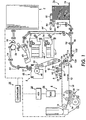
- the electrophotographic printing machine employs a photoconductive belt 10.
- the photoconductive belt 10 is made from a photoconductive material coated on a ground layer, which, in turn, is coated on an anti-curl backing layer.
- the photoconductive material is made from a transport layer coated on a selenium generator layer. The transport layer transports positive charges from the generator layer.
- the generator layer is coated on an interface layer.
- the interface layer is coated on the ground layer made from a titanium coated Mylar®. The interface layer aids in the transfer of electrons to the ground layer.
- the ground layer is very thin and allows light to pass therethrough.
- Other suitable photoconductive materials, ground layers, and anti-curl backing layers may also be employed.
- Belt 10 moves in the direction of arrow 12 to advance successive portions sequentially through the various processing stations disposed about the path of movement thereof.
- Belt 10 is entrained about stripping roller 14, tensioning roller 16, idler roll 18 and drive roller 20.
- Stripping roller 14 and idler roller 18 are mounted rotatably so as to rotate with belt 10.
- Tensioning roller 16 is resiliently urged against belt 10 to maintain belt 10 under the desired tension.
- Drive roller 20 is rotated by a motor coupled thereto by suitable means such as a belt drive. As roller 20 rotates, it advances belt 10 in the direction of arrow 12.
- a portion of the photoconductive surface passes through charging station A.
- two corona generating devices indicated generally by the reference numerals 22 and 24 charge the photoconductive belt 10 to a relatively high, substantially uniform potential.
- Corona generating device 22 places all of the required charge on photoconductive belt 10.
- Corona generating device 24 acts as a leveling device, and fills in any areas missed by corona generating device 22.
- the charged portion of the photoconductive surface is advanced through imaging station B.
- a raster output scanner indicated generally by the reference numeral 26 discharges selectively those portions of the charge corresponding to the image portions of the document to be reproduced. In this way, an electrostatic latent image is recorded on the photoconductive surface.
- An electronic subsystem indicated generally by the reference numerals 28, controls ROS 26.
- E S S 28 is adapted to receive signals from a computer and transpose these signals into suitable signals for controlling ROS 26 so as to record an electrostatic latent image corresponding to the document to be reproduced by the printing machine.
- ROS 26 may include a laser with a rotating polygon mirror block. The ROS 26 illuminates the charged portion of the photoconductive surface.
- a raster electrostatic latent image is recorded on the photoconductive surface which corresponds to the desired information to be printed on the sheet.
- Other types of imaging systems may also be used employing, for example, a pivoting or shiftable LED write bar or projection LCD (liquid crystal display) or other electro-optic display as the "write" source.
- belt 10 advances the electrostatic latent image recorded thereon to development station C.
- Development station C has three magnetic brush developer rolls indicated generally by the reference numerals 34, 36 and 38.
- a paddle wheel picks up developer material and delivers it to the developer rolls. When the developer material reaches rolls 34 and 36, it is magnetically split between the rolls with half of the developer material being delivered to each roll.
- Photoconductive belt 10 is partially wrapped about rolls 34 and 36 to form extended development zones.
- Developer roll 38 is a clean-up roll.
- a magnetic roll, positioned after developer roll 38, in the direction of arrow 12 is a carrier granule removal device adapted to remove any carrier granules adhering to belt 10.
- rolls 34 and 36 advance developer material into contact with the electrostatic latent image.
- the latent image attracts toner particles from the carrier granules of the developer material to form a toner powder image on the photoconductive surface of belt 10.
- Belt 10 then advances the toner powder image to transfer station D.
- a copy sheet is moved into contact with the toner powder image.
- photoconductive belt 10 is exposed to a pre-transfer light from a lamp (not shown) to reduce the attraction between photoconductive belt 10 and the toner powder image.
- a corona generating device 40 charges the copy sheet to the proper magnitude and polarity so that the copy sheet is tacked to photoconductive belt 10 and the toner powder image attracted from the photoconductive belt to the copy sheet.
- corona generator 42 charges the copy sheet to the opposite polarity to detack the copy sheet from belt 10.
- Conveyor 44 advances the copy sheet to fusing station E.
- Fusing station E includes a fuser assembly indicated generally by the reference numeral 46 which permanently affixes the transferred toner powder image to the copy sheet.
- fuser assembly 46 includes a heated fuser roller 48 and a pressure roller 50 with the powder image on the copy sheet contacting fuser roller 48.
- the pressure roller is cammed against the fuser roller to provide the necessary pressure to fix the toner powder image to the copy sheet.
- the fuser roll is internally heated by a quartz lamp.
- Release agent stored in a reservoir, is pumped to a metering roll. A trim blade trims off the excess release agent. The release agent transfers to a donor roll and then to the fuser roll.
- the copy sheets are fed through a decurler 52.
- Decurler 52 bends the copy sheet in one direction to put a known curl in the copy sheet and then bends it in the opposite direction to remove that curl.
- Forwarding rollers 54 then advance the sheet to duplex turn roll 56.
- Duplex solenoid gate 58 guides the sheet to the finishing station F, or to duplex tray 60.
- finishing station F copy sheets are stacked in a compiler tray and attached to one another to form sets. The sheets can be attached to one another by either a binder or a stapler. In either case, a plurality of sets of documents are formed in finishing station F.
- duplex solenoid gate 58 diverts the sheet into duplex tray 60.
- Duplex tray 60 provides an intermediate or buffer storage for those sheets that have been printed on one side and on which an image will be subsequently printed on the second, opposite side thereof, i.e., the sheets being duplexed.
- the sheets are stacked in duplex tray 60 face down on top of one another in the order in which they are copied.
- the simplex sheets in tray 60 are fed, in seriatim, by bottom feeder 62 from tray 60 back to transfer station D via conveyor 64 and rollers 66 for transfer of the toner powder image to the opposed sides of the copy sheets.
- bottom feeder 62 Inasmuch as successive bottom sheets are fed from duplex tray 60, the proper or clean side of the copy sheet is positioned in contact with belt 10 at transfer station D so that the toner powder image is transferred thereto.
- the duplex sheet is then fed through the same path as the simplex sheet to be advanced to finishing station F.
- Copy sheets are fed to transfer station D from the secondary tray 68.
- the secondary tray 68 includes an elevator driven by a bidirectional AC motor. Its controller has the ability to drive the tray up or down. When the tray is in the down position, stacks of copy sheets are loaded thereon or unloaded therefrom. In the up position, successive copy sheets may be fed therefrom by sheet feeder 70.
- Sheet feeder 70 is a friction retard feeder utilizing a feed belt and take-away rolls to advance successive copy sheets to transport 64 which advances the sheets to rolls 98 which feed the sheets to the registration device of the invention herein, described in detail below, and then to transfer station D.
- Copy sheets may also be fed to transfer station D from the auxiliary tray 72.
- the auxiliary tray 72 includes an elevator driven by a directional AC motor. Its controller has the ability to drive the tray up or down. When the tray is in the down position, stacks of copy sheets are loaded thereon or unloaded therefrom. In the up position, successive copy sheets may be fed therefrom by sheet feeder 74.
- Sheet feeder 74 is a friction retard feeder utilizing a feed belt and take-away rolls to advance successive copy sheets to transport 64 which advances the sheets to rolls 98 to the registration device and then to transfer station D.
- Secondary tray 68 and auxiliary tray 72 are secondary sources of copy sheets.
- the high capacity sheet feeder indicated generally by the reference numeral 76, is the primary source of copy sheets.
- Feed belt 81 feeds successive uppermost sheets from the stack to a take-away drive roll 82 and idler rolls 84.
- the drive roll and idler rolls guide the sheet onto transport 86.
- Transport 86 advances the sheet to rolls 98 which, in turn, move the sheet through the registration device to transfer station D.
- photoconductive belt 10 passes beneath corona generating device 94 which charges the residual toner particles to the proper polarity. Thereafter, the pre-charge erase lamp (not shown), located inside photoconductive belt 10, discharges the photoconductive belt in preparation for the next charging cycle. Residual particles are removed from the photoconductive surface at cleaning station G.
- Cleaning station G includes an electrically biased cleaner brush 88 and two de-toning rolls. The reclaim roll is electrically biased negatively relative to the cleaner roll so as to remove toner particles therefrom. The waste roll is electrically biased positively relative to the reclaim roll so as to remove paper debris and wrong sign toner particles. The toner particles on the reclaim roll are scraped off and deposited in a reclaim auger (not shown), where it is transported out of the rear of cleaning station G.
- the various machine functions are regulated by a controller 29.
- the controller 29 is preferably a programmable microprocessor which controls all of the machine functions hereinbefore described.
- the controller provides a comparison count of the copy sheets, the number of documents being recirculated, the number of copy sheets selected by the operator, time delays, jam corrections, etc.
- the control of all the exemplary systems heretofore described may be accomplished by conventional control switch inputs from the printing machine consoles selected by the operator.
- Conventional sheet path sensors or switches may be utilized to keep track of the position of the document and the copy sheets.
- the controller regulates the various positions of the gates depending upon the mode of operation selected.
- the invention herein has been illustrated in a high speed black and white printing machine. It is also very suitable for use in a high speed full color or highlight color printing machine where accurate sheet to image registration is critical.
- High quality documents require registration of sheets of paper to the photoreceptor for image transfer.
- Accurate registration control locates the image consistently with respect to the edge of the paper.
- each copy sheet 11 is delivered from the paper tray to the registration mechanisms by standard conveyance means.
- the registration mechanisms consist of two separately programmed pinch rollers 114, 116 laterally disposed with respect to the process direction.
- the position of the pinch rollers should always remain in control of the sheets while the distance between rollers should be maximized for best performance.
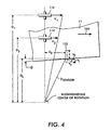
- a linear position sensor 132 positioned with its long axis substantially transverse to the process direction designated by arrow 100 so as to always be partially covered by one of the lateral edges of the sheet 11.
- Two possible arrangements are shown in Fig. 2 and Fig. 3. In the former, the sensor 132 is in line with the pinch rollers 114, 116 and in the latter the sensor 132 is not in line with the rollers 114, 116.
- Fig. 4 graphically indicates the concept of skew determination where P is the desired registration position at the sensor.
- the configuration of Fig. 2 offers the simplification of having a lateral velocity V l component of the sheet equal zero.
Landscapes
- Physics & Mathematics (AREA)
- General Physics & Mathematics (AREA)
- Registering Or Overturning Sheets (AREA)
- Paper Feeding For Electrophotography (AREA)
- Controlling Sheets Or Webs (AREA)
Claims (2)
- Procédé pour aligner et corriger le désalignement d'une feuille (11) le long d'un chemin de papier, comprenant :caractérisé en ce quela détection d'une position de bord avant et d'une position de bord latéral de ladite feuille (11) avec un seul capteur (132) ;la détermination d'une erreur d'inclinaison et d'une erreur de position d'alignement de la feuille (11) et la génération de signaux indiquant celles-ci ;l'entraínement d'une paire de lignes de contact d'entraínement (114, 116) indépendamment, en fonction d'un ensemble de signaux qui sont fonctions de l'erreur d'inclinaison et de l'erreur de position d'alignement de sorte que la feuille (11) arrive au niveau d'une position d'alignement aval dans le chemin de papier depuis le seul capteur (132) à un moment approprié et dans une position d'alignement correcte,
la détermination de l'erreur d'inclinaison comprend l'utilisation de données de vitesses des lignes..de contact d'entraínement de chaque ligne de contact d'entraínement de la paire de lignes de contact (114, 116) entraínées indépendamment et la détection des données dudit seul capteur (132). - Procédé selon la revendication 1, comprenant en outre la vérification d'une position de la feuille au niveau de la position d'alignement avec un seul deuxième capteur (134) et l'envoi des informations relatives à la position à un contrôleur pour mettre à jour une fonction de commande d'entraínement.
Applications Claiming Priority (2)
| Application Number | Priority Date | Filing Date | Title |
|---|---|---|---|
| US4293 | 1998-01-08 | ||
| US09/004,293 US5887996A (en) | 1998-01-08 | 1998-01-08 | Apparatus and method for sheet registration using a single sensor |
Publications (3)
| Publication Number | Publication Date |
|---|---|
| EP0928763A2 EP0928763A2 (fr) | 1999-07-14 |
| EP0928763A3 EP0928763A3 (fr) | 2002-12-04 |
| EP0928763B1 true EP0928763B1 (fr) | 2005-03-30 |
Family
ID=21710069
Family Applications (1)
| Application Number | Title | Priority Date | Filing Date |
|---|---|---|---|
| EP99100204A Expired - Lifetime EP0928763B1 (fr) | 1998-01-08 | 1999-01-07 | Procédé pour aligner des feuilles utilisant un seul capteur |
Country Status (4)
| Country | Link |
|---|---|
| US (1) | US5887996A (fr) |
| EP (1) | EP0928763B1 (fr) |
| JP (1) | JPH11255382A (fr) |
| DE (1) | DE69924414T2 (fr) |
Families Citing this family (50)
| Publication number | Priority date | Publication date | Assignee | Title |
|---|---|---|---|---|
| FR2768656B1 (fr) * | 1997-09-23 | 1999-12-10 | Neopost Ind | Dispositif de reorientation d'enveloppe |
| US6269995B1 (en) | 1998-04-29 | 2001-08-07 | Gerber Scientific Products, Inc. | Friction drive apparatus for strip material |
| US6283655B1 (en) | 1998-06-30 | 2001-09-04 | Gerber Scientific Products, Inc. | Friction-feed plotter with laterally-movable drive roller, and related method for plotting on sheets of different widths |
| US6229556B1 (en) * | 1998-10-15 | 2001-05-08 | Identity Group, Inc. | Printer and method of using same to print on thermoplastic medium |
| US6637634B1 (en) * | 1998-12-21 | 2003-10-28 | Gerber Scientific Products, Inc. | Methods for calibration and automatic alignment in friction drive apparatus |
| JP2000198581A (ja) * | 1998-12-28 | 2000-07-18 | Fujitsu Ltd | シ―ト供給装置及び記録装置 |
| US6338483B1 (en) | 1999-11-23 | 2002-01-15 | Jeffrey L. Andela | Single sheet feeder with selectively engageable prefeeding rolls |
| US6374075B1 (en) * | 2000-04-28 | 2002-04-16 | Xerox Corporation | Printing systems and methods |
| DE10023919A1 (de) * | 2000-05-17 | 2001-11-22 | Nexpress Solutions Llc | Verfahren zur Ausrichtung bogenförmigen Materials |
| US6511239B1 (en) * | 2000-11-17 | 2003-01-28 | Xerox Corporation | Flyer determination and elimination for side edge electronic registration |
| US6330424B1 (en) * | 2000-11-21 | 2001-12-11 | Lexmark International, Inc. | Method and apparatus for minimizing the open loop paper positional error in a control system for an electrophotographic printing apparatus |
| US6873820B2 (en) * | 2001-03-30 | 2005-03-29 | Canon Kabushiki Kaisha | Image forming apparatus |
| US6578844B2 (en) | 2001-04-10 | 2003-06-17 | Xerox Corporation | Sheet feeder |
| US6603953B2 (en) | 2001-12-14 | 2003-08-05 | Hewlett-Packard Development Company, L.P. | Nipped rollers for centering images on sheet media |
| DE10236028A1 (de) * | 2002-08-06 | 2004-02-19 | Giesecke & Devrient Gmbh | Vorrichtung und Verfahren für das Ausrichten von Banknoten |
| DE60311376T2 (de) | 2002-09-27 | 2007-11-29 | Eastman Kodak Co. | System zum Einstellen der Ausricht- und Taktgeschwindigkeit |
| US7088947B1 (en) | 2002-09-30 | 2006-08-08 | Eastman Kodak Company | Post processor inserter speed and timing adjust unit |
| JP2004182414A (ja) * | 2002-12-04 | 2004-07-02 | Noritsu Koki Co Ltd | 画像記録装置 |
| US6997455B2 (en) * | 2004-02-09 | 2006-02-14 | Eastman Kodak Company | Sheet deskewing method and apparatus |
| US20060197038A1 (en) * | 2005-06-13 | 2006-09-07 | Xerox Corporation | Incoming sheet skew, lateral and process position detection with an angled transverse sensor array bar |
| US7748708B2 (en) * | 2006-07-17 | 2010-07-06 | Xerox Corporation | Feedback-based document handling control system |
| US7628398B2 (en) * | 2006-07-17 | 2009-12-08 | Xerox Corporation | Feedback-based document handling control system |
| US8270049B2 (en) | 2006-08-01 | 2012-09-18 | Xerox Corporation | System and method for high resolution characterization of spatial variance of color separation misregistration |
| US8274717B2 (en) * | 2006-08-01 | 2012-09-25 | Xerox Corporation | System and method for characterizing color separation misregistration |
| US7894109B2 (en) | 2006-08-01 | 2011-02-22 | Xerox Corporation | System and method for characterizing spatial variance of color separation misregistration |
| JP4810407B2 (ja) * | 2006-11-15 | 2011-11-09 | キヤノン株式会社 | シート給送装置及び画像形成装置 |
| US7712737B2 (en) * | 2006-12-06 | 2010-05-11 | Xerox Corporation | Gain-scheduled feedback document handling control system |
| US7712738B2 (en) * | 2006-12-06 | 2010-05-11 | Xerox Corporation | Gain-scheduled feedback document handling control system |
| US7826095B2 (en) * | 2007-01-16 | 2010-11-02 | Xerox Corporation | System and method for estimating color separation misregistration utilizing frequency-shifted halftone patterns that form a moiré pattern |
| US7630672B2 (en) * | 2007-05-21 | 2009-12-08 | Xerox Corporation | System and method for determining and correcting color separation registration errors in a multi-color printing system |
| US8228559B2 (en) * | 2007-05-21 | 2012-07-24 | Xerox Corporation | System and method for characterizing color separation misregistration utilizing a broadband multi-channel scanning module |
| US7914000B2 (en) * | 2007-06-06 | 2011-03-29 | Xerox Corporation | Feedback-based document handling control system |
| US7806404B2 (en) * | 2007-11-09 | 2010-10-05 | Xerox Corporation | Skew adjustment of print sheets by loading force adjustment of idler wheel |
| US7914001B2 (en) * | 2008-06-12 | 2011-03-29 | Xerox Corporation | Systems and methods for determining skew contribution in lateral sheet registration |
| JP5163378B2 (ja) * | 2008-09-09 | 2013-03-13 | コニカミノルタビジネステクノロジーズ株式会社 | 用紙搬送装置及び画像形成装置 |
| US20100090391A1 (en) * | 2008-10-10 | 2010-04-15 | Xerox Corporation | Nip release system |
| US7922169B2 (en) * | 2008-10-29 | 2011-04-12 | Xerox Corporation | Friction retard feeder |
| US8573592B2 (en) * | 2009-03-06 | 2013-11-05 | Xerox Corporation | Inline skew and lateral measurement of a sheet during printing |
| US8746692B2 (en) * | 2009-04-30 | 2014-06-10 | Xerox Corporation | Moveable drive nip |
| US8020858B2 (en) * | 2009-05-29 | 2011-09-20 | Xerox Corporation | Accurate sheet leading edge registration system and method |
| US8348264B2 (en) * | 2009-06-30 | 2013-01-08 | Xerox Corporation | Two-point registration device control |
| US8317191B2 (en) * | 2009-10-13 | 2012-11-27 | Xerox Corporation | Sheet registration using multiple elongated sensors |
| DE102009046086B4 (de) | 2009-10-28 | 2014-01-30 | Koenig & Bauer Aktiengesellschaft | Ausrichteinheit einer Bogen verarbeitenden Maschine und ein Verfahren zum Abbremsen und Ausrichten zumindest eines Bogens |
| DE102009046089A1 (de) | 2009-10-28 | 2011-05-05 | Koenig & Bauer Aktiengesellschaft | Bogenanleger einer Bogen verarbeitenden Maschine |
| US8470733B2 (en) * | 2009-12-22 | 2013-06-25 | Zih Corp. | Direct thermal media and registration sensor system and method for use in a color thermal printer |
| US8083228B2 (en) * | 2009-12-28 | 2011-12-27 | Xerox Corporation | Closed loop lateral and skew control |
| US9056736B2 (en) * | 2013-07-15 | 2015-06-16 | Eastman Kodak Company | Media-tracking system using thermally-formed holes |
| US9751713B2 (en) * | 2014-12-18 | 2017-09-05 | Lexmark International, Inc. | Multiple edge media stapling system |
| US10363756B1 (en) * | 2018-05-17 | 2019-07-30 | Xerox Corporation | System and method for de-skewing substrates and laterally registering images on the substrates in a printer |
| CN114616200A (zh) * | 2019-10-25 | 2022-06-10 | 惠普发展公司,有限责任合伙企业 | 歪斜检测 |
Family Cites Families (16)
| Publication number | Priority date | Publication date | Assignee | Title |
|---|---|---|---|---|
| US4438917A (en) * | 1981-10-16 | 1984-03-27 | International Business Machines Corporation | Dual motor aligner |
| US4511242A (en) * | 1982-12-22 | 1985-04-16 | International Business Machines Corporation | Electronic alignment for a paper processing machine |
| JPS59186845A (ja) * | 1983-04-05 | 1984-10-23 | Ricoh Co Ltd | 紙葉体の搬送状態検出装置 |
| US4519700A (en) * | 1983-12-28 | 1985-05-28 | International Business Machines Corporation | Electronically gated paper aligner system |
| US4971304A (en) * | 1986-12-10 | 1990-11-20 | Xerox Corporation | Apparatus and method for combined deskewing and side registering |
| US5094442A (en) * | 1990-07-30 | 1992-03-10 | Xerox Corporation | Translating electronic registration system |
| US5078384A (en) * | 1990-11-05 | 1992-01-07 | Xerox Corporation | Combined differential deskewing and non-differential registration of sheet material using plural motors |
| US5156391A (en) * | 1991-11-04 | 1992-10-20 | Xerox Corporation | Short paper path electronic deskew system |
| US5169140A (en) * | 1991-11-25 | 1992-12-08 | Xerox Corporation | Method and apparatus for deskewing and side registering a sheet |
| US5278624A (en) * | 1992-07-07 | 1994-01-11 | Xerox Corporation | Differential drive for sheet registration drive rolls with skew detection |
| US5273274A (en) * | 1992-09-04 | 1993-12-28 | Xerox Corporation | Sheet feeding system with lateral registration and method for registering sheets |
| US5349199A (en) * | 1993-04-29 | 1994-09-20 | Xerox Corporation | Sensing apparatus for reducing sheet detection and registration errors by using multiple light beam reflections |
| JPH07257799A (ja) * | 1994-03-18 | 1995-10-09 | Oki Electric Ind Co Ltd | プリンタ及びその用紙振り分け方法 |
| JP3258203B2 (ja) * | 1994-07-26 | 2002-02-18 | 三菱電機株式会社 | シート搬送装置 |
| DE69609494T2 (de) * | 1996-06-17 | 2001-03-29 | C.P. Bourg S.A., Ottignies | Verfahren zum Ausrichten von Bogen und Blattstapler mit einer Blattausrichtungseinrichtung |
| US5678159A (en) * | 1996-06-26 | 1997-10-14 | Xerox Corporation | Sheet registration and deskewing device |
-
1998
- 1998-01-08 US US09/004,293 patent/US5887996A/en not_active Expired - Lifetime
-
1999
- 1999-01-06 JP JP11000868A patent/JPH11255382A/ja active Pending
- 1999-01-07 DE DE69924414T patent/DE69924414T2/de not_active Expired - Lifetime
- 1999-01-07 EP EP99100204A patent/EP0928763B1/fr not_active Expired - Lifetime
Also Published As
| Publication number | Publication date |
|---|---|
| EP0928763A3 (fr) | 2002-12-04 |
| EP0928763A2 (fr) | 1999-07-14 |
| DE69924414T2 (de) | 2005-08-11 |
| DE69924414D1 (de) | 2005-05-04 |
| US5887996A (en) | 1999-03-30 |
| JPH11255382A (ja) | 1999-09-21 |
Similar Documents
| Publication | Publication Date | Title |
|---|---|---|
| EP0928763B1 (fr) | Procédé pour aligner des feuilles utilisant un seul capteur | |
| US6059284A (en) | Process, lateral and skew sheet positioning apparatus and method | |
| US5697608A (en) | Agile lateral and shew sheet registration apparatus and method | |
| US5678159A (en) | Sheet registration and deskewing device | |
| US5697609A (en) | Lateral sheet pre-registration device | |
| CA2215431C (fr) | Systeme et methode de calibration pour le reperage et le realignement de feuillets | |
| US5720478A (en) | Gateless duplex inverter | |
| US5207416A (en) | Stack height sensing system | |
| US6137989A (en) | Sensor array and method to correct top edge misregistration | |
| CA2021746C (fr) | Decalage selectif de paquets de feuilles de papier | |
| US5335903A (en) | High capacity dual tray variable sheet size sheet feeder | |
| US4947214A (en) | Transfer apparatus | |
| EP0363153B1 (fr) | Dispositif pour détecter le bord d'une feuille | |
| US5374051A (en) | Relief device for offset stacker tamping mechanism | |
| US5657983A (en) | Wear resistant registration edge guide | |
| US5467171A (en) | Compact active steering roll for belt loops | |
| US6341777B1 (en) | Multiple-position idler roller | |
| US5086319A (en) | Multiple servo system for compensation of document mis-registration | |
| EP0361850B1 (fr) | Dispositif d'alimentation et de mise à niveau des feuilles | |
| US5941518A (en) | Sheet feeder with variable length, variable speed sheetpath | |
| US5300993A (en) | Transfer assist apparatus | |
| US5815766A (en) | Method and apparatus for clean convenient copy sheet jam clearance in an electrostatographic machine | |
| US20090152806A1 (en) | Sheet lateral positioning device | |
| US6201937B1 (en) | Image to paper registration utilizing differential transfer | |
| US5539508A (en) | Variable length transfer assist apparatus |
Legal Events
| Date | Code | Title | Description |
|---|---|---|---|
| PUAI | Public reference made under article 153(3) epc to a published international application that has entered the european phase |
Free format text: ORIGINAL CODE: 0009012 |
|
| AK | Designated contracting states |
Kind code of ref document: A2 Designated state(s): AT BE CH CY DE DK ES FI FR GB GR IE IT LI LU MC NL PT SE |
|
| AX | Request for extension of the european patent |
Free format text: AL;LT;LV;MK;RO;SI |
|
| PUAL | Search report despatched |
Free format text: ORIGINAL CODE: 0009013 |
|
| AK | Designated contracting states |
Kind code of ref document: A3 Designated state(s): AT BE CH CY DE DK ES FI FR GB GR IE IT LI LU MC NL PT SE |
|
| AX | Request for extension of the european patent |
Free format text: AL;LT;LV;MK;RO;SI |
|
| 17P | Request for examination filed |
Effective date: 20030604 |
|
| AKX | Designation fees paid |
Designated state(s): DE FR GB |
|
| 17Q | First examination report despatched |
Effective date: 20040324 |
|
| GRAP | Despatch of communication of intention to grant a patent |
Free format text: ORIGINAL CODE: EPIDOSNIGR1 |
|
| RTI1 | Title (correction) |
Free format text: METHOD FOR SHEET REGISTRATION USING A SINGLE SENSOR |
|
| GRAS | Grant fee paid |
Free format text: ORIGINAL CODE: EPIDOSNIGR3 |
|
| GRAA | (expected) grant |
Free format text: ORIGINAL CODE: 0009210 |
|
| AK | Designated contracting states |
Kind code of ref document: B1 Designated state(s): DE FR GB |
|
| REG | Reference to a national code |
Ref country code: GB Ref legal event code: FG4D |
|
| REF | Corresponds to: |
Ref document number: 69924414 Country of ref document: DE Date of ref document: 20050504 Kind code of ref document: P |
|
| ET | Fr: translation filed | ||
| PLBE | No opposition filed within time limit |
Free format text: ORIGINAL CODE: 0009261 |
|
| STAA | Information on the status of an ep patent application or granted ep patent |
Free format text: STATUS: NO OPPOSITION FILED WITHIN TIME LIMIT |
|
| 26N | No opposition filed |
Effective date: 20060102 |
|
| REG | Reference to a national code |
Ref country code: FR Ref legal event code: PLFP Year of fee payment: 18 |
|
| PGFP | Annual fee paid to national office [announced via postgrant information from national office to epo] |
Ref country code: GB Payment date: 20151224 Year of fee payment: 18 |
|
| PGFP | Annual fee paid to national office [announced via postgrant information from national office to epo] |
Ref country code: FR Payment date: 20151222 Year of fee payment: 18 |
|
| PGFP | Annual fee paid to national office [announced via postgrant information from national office to epo] |
Ref country code: DE Payment date: 20151217 Year of fee payment: 18 |
|
| REG | Reference to a national code |
Ref country code: DE Ref legal event code: R119 Ref document number: 69924414 Country of ref document: DE |
|
| GBPC | Gb: european patent ceased through non-payment of renewal fee |
Effective date: 20170107 |
|
| REG | Reference to a national code |
Ref country code: FR Ref legal event code: ST Effective date: 20170929 |
|
| PG25 | Lapsed in a contracting state [announced via postgrant information from national office to epo] |
Ref country code: FR Free format text: LAPSE BECAUSE OF NON-PAYMENT OF DUE FEES Effective date: 20170131 |
|
| PG25 | Lapsed in a contracting state [announced via postgrant information from national office to epo] |
Ref country code: DE Free format text: LAPSE BECAUSE OF NON-PAYMENT OF DUE FEES Effective date: 20170801 Ref country code: GB Free format text: LAPSE BECAUSE OF NON-PAYMENT OF DUE FEES Effective date: 20170107 |