EP0928886A2 - Mono-Endkammer für eine Zweikreiswärmetauscheranlage - Google Patents
Mono-Endkammer für eine Zweikreiswärmetauscheranlage Download PDFInfo
- Publication number
- EP0928886A2 EP0928886A2 EP99300024A EP99300024A EP0928886A2 EP 0928886 A2 EP0928886 A2 EP 0928886A2 EP 99300024 A EP99300024 A EP 99300024A EP 99300024 A EP99300024 A EP 99300024A EP 0928886 A2 EP0928886 A2 EP 0928886A2
- Authority
- EP
- European Patent Office
- Prior art keywords
- heat exchange
- tubes
- exchange circuit
- coolant
- radiator
- Prior art date
- Legal status (The legal status is an assumption and is not a legal conclusion. Google has not performed a legal analysis and makes no representation as to the accuracy of the status listed.)
- Granted
Links
- 230000009977 dual effect Effects 0.000 title 1
- 239000012530 fluid Substances 0.000 claims abstract description 42
- 239000002826 coolant Substances 0.000 claims description 67
- 238000002485 combustion reaction Methods 0.000 claims description 5
- 239000003570 air Substances 0.000 description 13
- 239000012080 ambient air Substances 0.000 description 1
- 238000001816 cooling Methods 0.000 description 1
- 230000001419 dependent effect Effects 0.000 description 1
- 238000010586 diagram Methods 0.000 description 1
- 238000002955 isolation Methods 0.000 description 1
- 239000002918 waste heat Substances 0.000 description 1
Images

Classifications
-
- F—MECHANICAL ENGINEERING; LIGHTING; HEATING; WEAPONS; BLASTING
- F28—HEAT EXCHANGE IN GENERAL
- F28D—HEAT-EXCHANGE APPARATUS, NOT PROVIDED FOR IN ANOTHER SUBCLASS, IN WHICH THE HEAT-EXCHANGE MEDIA DO NOT COME INTO DIRECT CONTACT
- F28D1/00—Heat-exchange apparatus having stationary conduit assemblies for one heat-exchange medium only, the media being in contact with different sides of the conduit wall, in which the other heat-exchange medium is a large body of fluid, e.g. domestic or motor car radiators
- F28D1/02—Heat-exchange apparatus having stationary conduit assemblies for one heat-exchange medium only, the media being in contact with different sides of the conduit wall, in which the other heat-exchange medium is a large body of fluid, e.g. domestic or motor car radiators with heat-exchange conduits immersed in the body of fluid
- F28D1/04—Heat-exchange apparatus having stationary conduit assemblies for one heat-exchange medium only, the media being in contact with different sides of the conduit wall, in which the other heat-exchange medium is a large body of fluid, e.g. domestic or motor car radiators with heat-exchange conduits immersed in the body of fluid with tubular conduits
- F28D1/0408—Multi-circuit heat exchangers, e.g. integrating different heat exchange sections in the same unit or heat exchangers for more than two fluids
- F28D1/0426—Multi-circuit heat exchangers, e.g. integrating different heat exchange sections in the same unit or heat exchangers for more than two fluids with units having particular arrangement relative to the large body of fluid, e.g. with interleaved units or with adjacent heat exchange units in common air flow or with units extending at an angle to each other or with units arranged around a central element
- F28D1/0443—Combination of units extending one beside or one above the other
-
- B—PERFORMING OPERATIONS; TRANSPORTING
- B60—VEHICLES IN GENERAL
- B60L—PROPULSION OF ELECTRICALLY-PROPELLED VEHICLES; SUPPLYING ELECTRIC POWER FOR AUXILIARY EQUIPMENT OF ELECTRICALLY-PROPELLED VEHICLES; ELECTRODYNAMIC BRAKE SYSTEMS FOR VEHICLES IN GENERAL; MAGNETIC SUSPENSION OR LEVITATION FOR VEHICLES; MONITORING OPERATING VARIABLES OF ELECTRICALLY-PROPELLED VEHICLES; ELECTRIC SAFETY DEVICES FOR ELECTRICALLY-PROPELLED VEHICLES
- B60L1/00—Supplying electric power to auxiliary equipment of vehicles
- B60L1/003—Supplying electric power to auxiliary equipment of vehicles to auxiliary motors, e.g. for pumps, compressors
-
- B—PERFORMING OPERATIONS; TRANSPORTING
- B60—VEHICLES IN GENERAL
- B60L—PROPULSION OF ELECTRICALLY-PROPELLED VEHICLES; SUPPLYING ELECTRIC POWER FOR AUXILIARY EQUIPMENT OF ELECTRICALLY-PROPELLED VEHICLES; ELECTRODYNAMIC BRAKE SYSTEMS FOR VEHICLES IN GENERAL; MAGNETIC SUSPENSION OR LEVITATION FOR VEHICLES; MONITORING OPERATING VARIABLES OF ELECTRICALLY-PROPELLED VEHICLES; ELECTRIC SAFETY DEVICES FOR ELECTRICALLY-PROPELLED VEHICLES
- B60L1/00—Supplying electric power to auxiliary equipment of vehicles
- B60L1/02—Supplying electric power to auxiliary equipment of vehicles to electric heating circuits
-
- B—PERFORMING OPERATIONS; TRANSPORTING
- B60—VEHICLES IN GENERAL
- B60L—PROPULSION OF ELECTRICALLY-PROPELLED VEHICLES; SUPPLYING ELECTRIC POWER FOR AUXILIARY EQUIPMENT OF ELECTRICALLY-PROPELLED VEHICLES; ELECTRODYNAMIC BRAKE SYSTEMS FOR VEHICLES IN GENERAL; MAGNETIC SUSPENSION OR LEVITATION FOR VEHICLES; MONITORING OPERATING VARIABLES OF ELECTRICALLY-PROPELLED VEHICLES; ELECTRIC SAFETY DEVICES FOR ELECTRICALLY-PROPELLED VEHICLES
- B60L3/00—Electric devices on electrically-propelled vehicles for safety purposes; Monitoring operating variables, e.g. speed, deceleration or energy consumption
- B60L3/0023—Detecting, eliminating, remedying or compensating for drive train abnormalities, e.g. failures within the drive train
-
- B—PERFORMING OPERATIONS; TRANSPORTING
- B60—VEHICLES IN GENERAL
- B60L—PROPULSION OF ELECTRICALLY-PROPELLED VEHICLES; SUPPLYING ELECTRIC POWER FOR AUXILIARY EQUIPMENT OF ELECTRICALLY-PROPELLED VEHICLES; ELECTRODYNAMIC BRAKE SYSTEMS FOR VEHICLES IN GENERAL; MAGNETIC SUSPENSION OR LEVITATION FOR VEHICLES; MONITORING OPERATING VARIABLES OF ELECTRICALLY-PROPELLED VEHICLES; ELECTRIC SAFETY DEVICES FOR ELECTRICALLY-PROPELLED VEHICLES
- B60L3/00—Electric devices on electrically-propelled vehicles for safety purposes; Monitoring operating variables, e.g. speed, deceleration or energy consumption
- B60L3/0023—Detecting, eliminating, remedying or compensating for drive train abnormalities, e.g. failures within the drive train
- B60L3/003—Detecting, eliminating, remedying or compensating for drive train abnormalities, e.g. failures within the drive train relating to inverters
-
- B—PERFORMING OPERATIONS; TRANSPORTING
- B60—VEHICLES IN GENERAL
- B60L—PROPULSION OF ELECTRICALLY-PROPELLED VEHICLES; SUPPLYING ELECTRIC POWER FOR AUXILIARY EQUIPMENT OF ELECTRICALLY-PROPELLED VEHICLES; ELECTRODYNAMIC BRAKE SYSTEMS FOR VEHICLES IN GENERAL; MAGNETIC SUSPENSION OR LEVITATION FOR VEHICLES; MONITORING OPERATING VARIABLES OF ELECTRICALLY-PROPELLED VEHICLES; ELECTRIC SAFETY DEVICES FOR ELECTRICALLY-PROPELLED VEHICLES
- B60L50/00—Electric propulsion with power supplied within the vehicle
- B60L50/50—Electric propulsion with power supplied within the vehicle using propulsion power supplied by batteries or fuel cells
- B60L50/60—Electric propulsion with power supplied within the vehicle using propulsion power supplied by batteries or fuel cells using power supplied by batteries
- B60L50/61—Electric propulsion with power supplied within the vehicle using propulsion power supplied by batteries or fuel cells using power supplied by batteries by batteries charged by engine-driven generators, e.g. series hybrid electric vehicles
-
- F—MECHANICAL ENGINEERING; LIGHTING; HEATING; WEAPONS; BLASTING
- F01—MACHINES OR ENGINES IN GENERAL; ENGINE PLANTS IN GENERAL; STEAM ENGINES
- F01P—COOLING OF MACHINES OR ENGINES IN GENERAL; COOLING OF INTERNAL-COMBUSTION ENGINES
- F01P3/00—Liquid cooling
- F01P3/20—Cooling circuits not specific to a single part of engine or machine
-
- F—MECHANICAL ENGINEERING; LIGHTING; HEATING; WEAPONS; BLASTING
- F01—MACHINES OR ENGINES IN GENERAL; ENGINE PLANTS IN GENERAL; STEAM ENGINES
- F01P—COOLING OF MACHINES OR ENGINES IN GENERAL; COOLING OF INTERNAL-COMBUSTION ENGINES
- F01P7/00—Controlling of coolant flow
- F01P7/14—Controlling of coolant flow the coolant being liquid
- F01P7/16—Controlling of coolant flow the coolant being liquid by thermostatic control
- F01P7/165—Controlling of coolant flow the coolant being liquid by thermostatic control characterised by systems with two or more loops
-
- B—PERFORMING OPERATIONS; TRANSPORTING
- B60—VEHICLES IN GENERAL
- B60L—PROPULSION OF ELECTRICALLY-PROPELLED VEHICLES; SUPPLYING ELECTRIC POWER FOR AUXILIARY EQUIPMENT OF ELECTRICALLY-PROPELLED VEHICLES; ELECTRODYNAMIC BRAKE SYSTEMS FOR VEHICLES IN GENERAL; MAGNETIC SUSPENSION OR LEVITATION FOR VEHICLES; MONITORING OPERATING VARIABLES OF ELECTRICALLY-PROPELLED VEHICLES; ELECTRIC SAFETY DEVICES FOR ELECTRICALLY-PROPELLED VEHICLES
- B60L2200/00—Type of vehicles
- B60L2200/18—Buses
-
- B—PERFORMING OPERATIONS; TRANSPORTING
- B60—VEHICLES IN GENERAL
- B60L—PROPULSION OF ELECTRICALLY-PROPELLED VEHICLES; SUPPLYING ELECTRIC POWER FOR AUXILIARY EQUIPMENT OF ELECTRICALLY-PROPELLED VEHICLES; ELECTRODYNAMIC BRAKE SYSTEMS FOR VEHICLES IN GENERAL; MAGNETIC SUSPENSION OR LEVITATION FOR VEHICLES; MONITORING OPERATING VARIABLES OF ELECTRICALLY-PROPELLED VEHICLES; ELECTRIC SAFETY DEVICES FOR ELECTRICALLY-PROPELLED VEHICLES
- B60L2210/00—Converter types
- B60L2210/40—DC to AC converters
-
- B—PERFORMING OPERATIONS; TRANSPORTING
- B60—VEHICLES IN GENERAL
- B60L—PROPULSION OF ELECTRICALLY-PROPELLED VEHICLES; SUPPLYING ELECTRIC POWER FOR AUXILIARY EQUIPMENT OF ELECTRICALLY-PROPELLED VEHICLES; ELECTRODYNAMIC BRAKE SYSTEMS FOR VEHICLES IN GENERAL; MAGNETIC SUSPENSION OR LEVITATION FOR VEHICLES; MONITORING OPERATING VARIABLES OF ELECTRICALLY-PROPELLED VEHICLES; ELECTRIC SAFETY DEVICES FOR ELECTRICALLY-PROPELLED VEHICLES
- B60L2240/00—Control parameters of input or output; Target parameters
- B60L2240/10—Vehicle control parameters
- B60L2240/36—Temperature of vehicle components or parts
-
- B—PERFORMING OPERATIONS; TRANSPORTING
- B60—VEHICLES IN GENERAL
- B60L—PROPULSION OF ELECTRICALLY-PROPELLED VEHICLES; SUPPLYING ELECTRIC POWER FOR AUXILIARY EQUIPMENT OF ELECTRICALLY-PROPELLED VEHICLES; ELECTRODYNAMIC BRAKE SYSTEMS FOR VEHICLES IN GENERAL; MAGNETIC SUSPENSION OR LEVITATION FOR VEHICLES; MONITORING OPERATING VARIABLES OF ELECTRICALLY-PROPELLED VEHICLES; ELECTRIC SAFETY DEVICES FOR ELECTRICALLY-PROPELLED VEHICLES
- B60L2270/00—Problem solutions or means not otherwise provided for
- B60L2270/46—Heat pumps, e.g. for cabin heating
-
- F—MECHANICAL ENGINEERING; LIGHTING; HEATING; WEAPONS; BLASTING
- F01—MACHINES OR ENGINES IN GENERAL; ENGINE PLANTS IN GENERAL; STEAM ENGINES
- F01P—COOLING OF MACHINES OR ENGINES IN GENERAL; COOLING OF INTERNAL-COMBUSTION ENGINES
- F01P3/00—Liquid cooling
- F01P3/18—Arrangements or mounting of liquid-to-air heat-exchangers
- F01P2003/185—Arrangements or mounting of liquid-to-air heat-exchangers arranged in parallel
-
- F—MECHANICAL ENGINEERING; LIGHTING; HEATING; WEAPONS; BLASTING
- F01—MACHINES OR ENGINES IN GENERAL; ENGINE PLANTS IN GENERAL; STEAM ENGINES
- F01P—COOLING OF MACHINES OR ENGINES IN GENERAL; COOLING OF INTERNAL-COMBUSTION ENGINES
- F01P5/00—Pumping cooling-air or liquid coolants
- F01P5/10—Pumping liquid coolant; Arrangements of coolant pumps
- F01P2005/105—Using two or more pumps
-
- F—MECHANICAL ENGINEERING; LIGHTING; HEATING; WEAPONS; BLASTING
- F01—MACHINES OR ENGINES IN GENERAL; ENGINE PLANTS IN GENERAL; STEAM ENGINES
- F01P—COOLING OF MACHINES OR ENGINES IN GENERAL; COOLING OF INTERNAL-COMBUSTION ENGINES
- F01P2050/00—Applications
- F01P2050/02—Marine engines
- F01P2050/06—Marine engines using liquid-to-liquid heat exchangers
-
- F—MECHANICAL ENGINEERING; LIGHTING; HEATING; WEAPONS; BLASTING
- F01—MACHINES OR ENGINES IN GENERAL; ENGINE PLANTS IN GENERAL; STEAM ENGINES
- F01P—COOLING OF MACHINES OR ENGINES IN GENERAL; COOLING OF INTERNAL-COMBUSTION ENGINES
- F01P2050/00—Applications
- F01P2050/24—Hybrid vehicles
-
- F—MECHANICAL ENGINEERING; LIGHTING; HEATING; WEAPONS; BLASTING
- F01—MACHINES OR ENGINES IN GENERAL; ENGINE PLANTS IN GENERAL; STEAM ENGINES
- F01P—COOLING OF MACHINES OR ENGINES IN GENERAL; COOLING OF INTERNAL-COMBUSTION ENGINES
- F01P2060/00—Cooling circuits using auxiliaries
-
- F—MECHANICAL ENGINEERING; LIGHTING; HEATING; WEAPONS; BLASTING
- F01—MACHINES OR ENGINES IN GENERAL; ENGINE PLANTS IN GENERAL; STEAM ENGINES
- F01P—COOLING OF MACHINES OR ENGINES IN GENERAL; COOLING OF INTERNAL-COMBUSTION ENGINES
- F01P2060/00—Cooling circuits using auxiliaries
- F01P2060/04—Lubricant cooler
-
- F—MECHANICAL ENGINEERING; LIGHTING; HEATING; WEAPONS; BLASTING
- F01—MACHINES OR ENGINES IN GENERAL; ENGINE PLANTS IN GENERAL; STEAM ENGINES
- F01P—COOLING OF MACHINES OR ENGINES IN GENERAL; COOLING OF INTERNAL-COMBUSTION ENGINES
- F01P2060/00—Cooling circuits using auxiliaries
- F01P2060/04—Lubricant cooler
- F01P2060/045—Lubricant cooler for transmissions
-
- F—MECHANICAL ENGINEERING; LIGHTING; HEATING; WEAPONS; BLASTING
- F28—HEAT EXCHANGE IN GENERAL
- F28D—HEAT-EXCHANGE APPARATUS, NOT PROVIDED FOR IN ANOTHER SUBCLASS, IN WHICH THE HEAT-EXCHANGE MEDIA DO NOT COME INTO DIRECT CONTACT
- F28D21/00—Heat-exchange apparatus not covered by any of the groups F28D1/00 - F28D20/00
- F28D2021/0019—Other heat exchangers for particular applications; Heat exchange systems not otherwise provided for
- F28D2021/0028—Other heat exchangers for particular applications; Heat exchange systems not otherwise provided for for cooling heat generating elements, e.g. for cooling electronic components or electric devices
- F28D2021/0031—Radiators for recooling a coolant of cooling systems
-
- F—MECHANICAL ENGINEERING; LIGHTING; HEATING; WEAPONS; BLASTING
- F28—HEAT EXCHANGE IN GENERAL
- F28D—HEAT-EXCHANGE APPARATUS, NOT PROVIDED FOR IN ANOTHER SUBCLASS, IN WHICH THE HEAT-EXCHANGE MEDIA DO NOT COME INTO DIRECT CONTACT
- F28D21/00—Heat-exchange apparatus not covered by any of the groups F28D1/00 - F28D20/00
- F28D2021/0019—Other heat exchangers for particular applications; Heat exchange systems not otherwise provided for
- F28D2021/008—Other heat exchangers for particular applications; Heat exchange systems not otherwise provided for for vehicles
- F28D2021/0091—Radiators
- F28D2021/0094—Radiators for recooling the engine coolant
-
- F—MECHANICAL ENGINEERING; LIGHTING; HEATING; WEAPONS; BLASTING
- F28—HEAT EXCHANGE IN GENERAL
- F28F—DETAILS OF HEAT-EXCHANGE AND HEAT-TRANSFER APPARATUS, OF GENERAL APPLICATION
- F28F9/00—Casings; Header boxes; Auxiliary supports for elements; Auxiliary members within casings
- F28F9/02—Header boxes; End plates
- F28F2009/0285—Other particular headers or end plates
- F28F2009/0287—Other particular headers or end plates having passages for different heat exchange media
-
- Y—GENERAL TAGGING OF NEW TECHNOLOGICAL DEVELOPMENTS; GENERAL TAGGING OF CROSS-SECTIONAL TECHNOLOGIES SPANNING OVER SEVERAL SECTIONS OF THE IPC; TECHNICAL SUBJECTS COVERED BY FORMER USPC CROSS-REFERENCE ART COLLECTIONS [XRACs] AND DIGESTS
- Y02—TECHNOLOGIES OR APPLICATIONS FOR MITIGATION OR ADAPTATION AGAINST CLIMATE CHANGE
- Y02T—CLIMATE CHANGE MITIGATION TECHNOLOGIES RELATED TO TRANSPORTATION
- Y02T10/00—Road transport of goods or passengers
- Y02T10/60—Other road transportation technologies with climate change mitigation effect
- Y02T10/62—Hybrid vehicles
-
- Y—GENERAL TAGGING OF NEW TECHNOLOGICAL DEVELOPMENTS; GENERAL TAGGING OF CROSS-SECTIONAL TECHNOLOGIES SPANNING OVER SEVERAL SECTIONS OF THE IPC; TECHNICAL SUBJECTS COVERED BY FORMER USPC CROSS-REFERENCE ART COLLECTIONS [XRACs] AND DIGESTS
- Y02—TECHNOLOGIES OR APPLICATIONS FOR MITIGATION OR ADAPTATION AGAINST CLIMATE CHANGE
- Y02T—CLIMATE CHANGE MITIGATION TECHNOLOGIES RELATED TO TRANSPORTATION
- Y02T10/00—Road transport of goods or passengers
- Y02T10/60—Other road transportation technologies with climate change mitigation effect
- Y02T10/70—Energy storage systems for electromobility, e.g. batteries
-
- Y—GENERAL TAGGING OF NEW TECHNOLOGICAL DEVELOPMENTS; GENERAL TAGGING OF CROSS-SECTIONAL TECHNOLOGIES SPANNING OVER SEVERAL SECTIONS OF THE IPC; TECHNICAL SUBJECTS COVERED BY FORMER USPC CROSS-REFERENCE ART COLLECTIONS [XRACs] AND DIGESTS
- Y02—TECHNOLOGIES OR APPLICATIONS FOR MITIGATION OR ADAPTATION AGAINST CLIMATE CHANGE
- Y02T—CLIMATE CHANGE MITIGATION TECHNOLOGIES RELATED TO TRANSPORTATION
- Y02T10/00—Road transport of goods or passengers
- Y02T10/60—Other road transportation technologies with climate change mitigation effect
- Y02T10/7072—Electromobility specific charging systems or methods for batteries, ultracapacitors, supercapacitors or double-layer capacitors
-
- Y—GENERAL TAGGING OF NEW TECHNOLOGICAL DEVELOPMENTS; GENERAL TAGGING OF CROSS-SECTIONAL TECHNOLOGIES SPANNING OVER SEVERAL SECTIONS OF THE IPC; TECHNICAL SUBJECTS COVERED BY FORMER USPC CROSS-REFERENCE ART COLLECTIONS [XRACs] AND DIGESTS
- Y02—TECHNOLOGIES OR APPLICATIONS FOR MITIGATION OR ADAPTATION AGAINST CLIMATE CHANGE
- Y02T—CLIMATE CHANGE MITIGATION TECHNOLOGIES RELATED TO TRANSPORTATION
- Y02T10/00—Road transport of goods or passengers
- Y02T10/60—Other road transportation technologies with climate change mitigation effect
- Y02T10/72—Electric energy management in electromobility
-
- Y—GENERAL TAGGING OF NEW TECHNOLOGICAL DEVELOPMENTS; GENERAL TAGGING OF CROSS-SECTIONAL TECHNOLOGIES SPANNING OVER SEVERAL SECTIONS OF THE IPC; TECHNICAL SUBJECTS COVERED BY FORMER USPC CROSS-REFERENCE ART COLLECTIONS [XRACs] AND DIGESTS
- Y02—TECHNOLOGIES OR APPLICATIONS FOR MITIGATION OR ADAPTATION AGAINST CLIMATE CHANGE
- Y02T—CLIMATE CHANGE MITIGATION TECHNOLOGIES RELATED TO TRANSPORTATION
- Y02T90/00—Enabling technologies or technologies with a potential or indirect contribution to GHG emissions mitigation
- Y02T90/10—Technologies relating to charging of electric vehicles
- Y02T90/16—Information or communication technologies improving the operation of electric vehicles
Definitions
- This invention is directed to a heat exchange system having a single core which is in fluid communication with two heat exchange circuits, and in particular, to a heat exchange system having a single core which is in fluid communication with a first heat exchange circuit in heat exchange relationship with an engine and a second heat exchange circuit in heat exchange relationship with an inverter.
- the engine, the inverter and the traction motor all generate heat. It is therefore necessary to equip the vehicle with a heat exchange system to remove a substantial portion of the heat generated by the engine, the inverter and the traction motor from the vehicle.
- One way in which the heat can be removed is by equipping the vehicle with a single core radiator and a single heat exchange circuit in fluid communication with the single core radiator and in heat exchange relationship with the engine, the inverter and the traction motor.
- a single core radiator and a single heat exchange circuit in fluid communication with the single core radiator and in heat exchange relationship with the engine, the inverter and the traction motor.
- the inverter it is necessary to keep the operating temperature of the coolant in heat exchange relationship with the inverter relatively low, approximately 70 C.
- a system has an engine, a generator driven by the engine to generate a DC voltage, and an inverter electrically coupled to the generator to convert the DC voltage to an AC signal.
- the system also has a first heat exchange circuit in heat exchange relationship with the engine to remove heat from the engine, and a second heat exchange circuit in heat exchange relationship with the inverter to remove heat from the inverter.
- the system further has a single radiator divided into first and second sections, the first section being substantially hydraulically isolated from fluid communication with the second section. The first section of the radiator is in fluid communication with the first heat exchange circuit, and the second section is in fluid communication with the second heat exchange circuit.
- the inverter supplies AC power to a traction motor for driving a vehicle.
- the first section of the radiator may have a first heat exchange zone and the second section of the radiator may have a second heat exchange zone, the first zone being larger than the second zone.
- the first section of the radiator may have a first plurality of tubes through which a coolant from the first heat exchange circuit may pass.
- the second section of the radiator may have a second plurality of tubes through which a coolant from the second heat exchange circuit may pass.
- the number of tubes in the first plurality of tubes may be greater than the number of tubes in the second plurality of tubes.
- the ratio of the number of tubes in the first plurality of tubes to the number of tubes in the second plurality of tubes may be about 6:1.
- the radiator may have a first tank, a second tank, a first plurality of tubes in fluid communication with the first and second tanks so that a coolant may pass between the first tank and the second tank through the first plurality of tubes and a second plurality of tubes in fluid communication with the first and second tanks so that a coolant may pass between the first tank and the second tank through the second plurality of tubes.
- the radiator may have first and second ports in fluid communication with the first tank in spaced relation to one another and first and second ports in fluid communication with the second tank in spaced relation to one another, two of the ports serving as inlets and two of the ports serving as outlets.
- One inlet and outlet may be in fluid communication with the first plurality of tubes and the first heat exchange circuit and the other inlet and outlet may be in fluid communication with the second plurality of tubes and the second heat exchange circuit.
- the radiator may have a first baffle disposed in the first tank between the first and second ports therein to hydraulically isolate the first port therein from the second port therein and a second baffle disposed in the second tank between the first and second ports therein to hydraulically isolate the first port therein from the second port therein to hydraulically isolate the first plurality of tubes from the second plurality of tubes.
- the number of tubes in the first plurality of tubes may be greater than the number of tubes in the second plurality of tubes.
- the first heat exchange circuit may have a first pump disposed between the engine and the port serving as the inlet between the radiator and the first heat exchange circuit to circulate a coolant in the first heat exchange circuit.
- the second heat exchange circuit may have a second pump disposed between the inverter and the port serving as the outlet between the radiator and the second heat exchange circuit to circulate a coolant in the second heat exchange circuit.
- the system may include a traction motor electrically coupled to the inverter, and an air compressor driven by the engine.
- the first heat exchange circuit may be in heat exchange relationship with the traction motor and the air compressor.
- the engine may be an internal combustion engine.
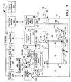
- a vehicle 20 is shown in Fig. 1.
- the vehicle 20 has a chassis 22 which mounts an engine 24, an air compressor 26, a generator 28, a battery or battery assembly 29, an inverter 30, a traction motor 32 and a drive assembly 34.
- the inverter 30 is electrically coupled to the battery or battery assembly 29 to invert the DC voltage of the battery or battery assembly 29 into an AC signal.
- the AC signal from the inverter 30 is used to power the traction motor 32, which drives the drive assembly 34 to propel the vehicle 20.
- the vehicle 20 also has a heat exchange system 36.
- the heat exchange system 36 includes a single core, single pass radiator 38 with first and second sections 40, 42 which are hydraulically separated from each other as will be explained in greater detail below.
- the heat exchange system 36 also includes first and second heat exchange circuits 44, 46.
- the first heat exchange circuit 44 is connected to the first section 40 between a first port 48 and a second port 50 of the radiator 38.
- the first heat exchange circuit 44 is in heat exchange relationship with the engine 24, the air compressor 26 and the traction motor 32 to cool each.
- the second heat exchange circuit 46 is connected to the second section 42 between a first port 52 and a second port 54 of the radiator 38.
- the second heat exchange circuit 46 is in heat exchange relationship with the inverter 30 to cool the same.
- the radiator 38 has a first tank 56 and a second tank 58.
- the first ports or outlets 48, 52 are formed in the first tank 56, while the second ports or inlets 50, 54 are formed in the second tank 58.
- the first ports 48, 52 are spaced from each other along the length of the first tank 56, and the second ports 50, 54 are spaced from each other along the length of the second tank 58.
- a baffle 60 is disposed in the first tank 56 between the first ports 48, 52.
- a similar baffle 62 is disposed in the second tank 58 between the second ports 50, 54.
- the baffles 60, 62 are secured to the interior walls 64, 66 of the first and second tanks 56, 58 to substantially prevent the communication of fluid between the first ports 48, 52 in the first tank 56 and the second ports 50, 54 in the second tank 58. That is, the baffles 60, 62 provide hydraulic isolation between the ports 48, 52 as well as between the ports 50, 54.
- the baffles 60, 62 may be of any shape, but should preferably conform to the shape of the interior walls 64, 66.
- the baffle 60 separates the first tank 56 into two first headers 68, 70. Similarly, the baffle 62 separates the second tank into two second headers 72, 74.
- a first plurality of tubes 76 which may be thin, flat tubes of non-circular cross-section, are disposed between the first header 68 and the second header 72.
- the tubes 76 are secured and sealed to the first header 68 at ends 78 and the second header 72 at ends 80 such that fluid from the second header 72 may pass through the tubes 76 to the first header 68.
- the tubes 76 are connected to the respective headers on one side of the baffles 60, 62.
- the tubes 76 present a first heat exchange zone for heat exchange between a coolant in the tubes and the ambient.
- a second plurality of tubes 82 which also may be thin, flat tubes of non-circular cross-section, are disposed between the first header 70 and the second header 74.
- the tubes 82 are secured and sealed to the first header 70 at ends 84 and the second header 74 at ends 86 such that fluid from the second header 74 may pass through the tubes 82 to the first header 70.
- the tubes 82 are connected to the respective headers on the side of the baffles 60, 62 opposite the tubes 76.
- the second plurality of tubes 82 presents a second heat exchange zone for heat exchange between a coolant in the tubes and the ambient.
- substantially all of the fluid passing from the second header 72 to the first header 68 passes through the tubes 76, while substantially all of the fluid passing from the second header 74 to the first header 70 passes through the tubes 82.
- the number of tubes 76 is greater than the number of tubes 82. Stated slightly differently, the heat exchange zone of the first section 40 is greater than the heat exchange zone of the second section 42.
- the radiator 38 also includes air side fins 87 which promote heat exchange between the tubes 76, 82 and the cooling air flow.
- the radiator 38 is in fluid communication with the first heat exchange circuit 44 which includes a traction motor heat exchange assembly 88, an engine jacket 90, an air compressor heat exchanger 92, a pump 94, and conduits 96, 98, 100, 102, 104, 106.
- the radiator 38 is also in fluid communication with the second heat exchange circuit 46 which includes an inverter heat exchanger 108, a pump 110, and conduits 112, 114, 116.
- Arrows 118, 120, 122, 124, 126, 128, 130, 132, 134 show the direction of flow of first and second coolants through the first and second circuits 44, 46 and the radiator 38.
- the first heat exchange circuit 44 is assembled as follows.
- the conduit 96 is attached at a first end 136 to the first port 48 of the radiator 38, and at a second end 138 to an inlet 140 of the traction motor heat exchanger assembly 88.
- the traction motor heat exchanger assembly 88 preferably includes a first heat exchanger in a direct heat exchange relationship with the traction motor 32 and using oil as the coolant, and a second heat exchanger wherein the oil is allowed to reject heat into the coolant stream passing through the first heat exchange circuit 44.
- the conduit 98 is attached at a first end 142 to an outlet 144 of the traction motor heat exchanger assembly 88, and at a second end 146 to an inlet 148 of the engine jacket 90.
- the conduit 100 is attached at a first end 150 to an outlet 152 of the engine jacket 90.
- the conduit 100 is also attached at a second end 154 to an inlet 156 of the pump 94.
- the conduits 102 and 104 are attached at first ends 158, 160 to an outlet 162 of the pump 94.
- the conduit 102 is attached at a second end 164 to an inlet 166 of the air compressor heat exchanger 92.
- the conduit 104 is attached at a second end 168 to an inlet 50 of the radiator 38.
- the conduit 106 is attached at a first end 170 to an outlet 172 of the air compressor heat exchanger 92.
- the conduit 106 is also attached at a second end 174 to the conduit 98.
- the second heat exchange circuit 46 is assembled as follows.
- the conduit 112 is attached at a first end 176 to the first port 52 of the radiator 38.
- the conduit 112 is attached at a second end 178 to an inlet 180 of the pump 110.
- the conduit 114 is attached at a first end 182 to an outlet 184 of the pump 110.
- the conduit 114 is also attached at a second end 186 to an inlet 188 of the inverter heat exchanger 108.
- the conduit 116 is attached at a first end 190 to an outlet 192 of the inverter heat exchanger 108.
- the conduit 116 is attached at a second end 194 to the second port 54 of the radiator 38.
- a first coolant would be circulated in the first circuit 44 as shown by arrows 118, 120, 122, 124, 126, 128.
- the coolant leaves the radiator 38 through the first port or outlet 48 of the first section 40 of the radiator 38 in the direction of arrow 118.
- the coolant exits the radiator 38 at an approximate temperature of 91 C (195° F), with a flow rate of approximately 187 kg/min (412 lbs./min.).
- the coolant passes through the conduit 96 into the inlet 140 of the traction motor heat exchanger 88.
- the coolant absorbs approximately 1.14 Mj/min. (1081 Btu/min.) as it passes through the traction motor heat exchanger 88.
- the coolant exits the traction motor heat exchanger 88 through the outlet 144 at a temperature of 91.7 C (197° F).
- the coolant then passes through the conduit 98 in the direction of arrow 120. Before the coolant enters the engine jacket 90, it is combined with coolant which has passed through the air compressor heat exchanger 92.
- the coolant exiting the air compressor heat exchanger 92 has an approximate temperature of 104 C (220° F), with a flow rate of 9 kg/min (20 lbs./min.).
- the coolant which passed through the air compressor heat exchanger 92 absorbed approximately 211 kj/min. (200 Btu/min.).
- the coolant entering the engine jacket 90 has a temperature of approximately 92 C (198° F), with a flow rate of 196 kg/min. (432 lbs./min.).
- the coolant passing through the engine jacket 90 absorbs 5.34 Mj/min. (5060 Btu/min.).
- the coolant emptying from the engine jacket 90 through outlet 152 into the conduit 100 does so at a temperature of approximately 99 C (210° F), with a flow rate of 196 kg/min. (432 lbs./min.).
- the coolant Shortly after the coolant exits the pump 94, the coolant divides into the conduits 102, 104, the conduit 102 returning to the air compressor heat exchanger 92, and the conduit 104 returning to the second port or inlet 50 of the section of the radiator 38.
- the coolant entering the radiator 38 through the inlet 50 is at a temperature of approximately 99 C (210° F) and at a flow rate of 187 kg/min. (412 lbs./min.).
- the first section 40 of the radiator 38 allows 6.67 Mj/min. (6341 Btu/min.) to be rejected to the ambient environment (approximately 49 C (120° F)), thus lowering the temperature of the coolant to 91 C (195° F).
- the coolant exits the first port or outlet 52 of the second section 42 of the radiator 38 at a temperature of 63 C (146° F) and at a flow rate of 30.5 kg/min. (67 lbs./min.).
- the coolant passes through the inlet 188 into the inverter heat exchanger 108, wherein the coolant absorbs 510 kj/min. (484 Btu/min.). This raises the temperature of the coolant exiting the inverter heat exchanger 108 at outlet 192 to 67 C (153° F).
- the second section 42 of the radiator 38 allows 510 kj/min. (484 Btu/min.) to be rejected to the ambient environment to return the temperature of the coolant to 63 C (146° F).
- the temperature of the coolant circulating in the first circuit 44 is approximately 27 C (49° F) higher than temperature of the coolant circulating in the second circuit 46 at the outlets 48, 52 of the radiator 38, and approximately 32 C (57° F) higher at the inlets 50, 54 ofthe radiator 38.
- the heat exchange system 36 provides for rejection of heat for the first circuit 44 in heat exchange relationship with the engine 24 at a substantially higher temperature differential relative to the ambient temperature than in the second circuit 46, while also allowing the coolant in the second circuit 46 to remain at a substantially lower temperature to protect the inverter 30.
- first coolant has been shown flowing through the first circuit 44 from the port 48 to the port 50 and the second coolant flowing through the second circuit 46 from the port 52 to the port 54, it is recognized that the flow of the coolants in either or both of the circuits could be reversed. If the flow of one or both of the coolants is reversed, then it may be necessary to change the position of the pumps 94, 110 relative to the ports so that the pump 94 remains connected between the outlet 152 of the engine jacket 90 and the first circuit radiator inlet, and the pump 110 remains connected between the second circuit radiator outlet and the inlet 188 of the inverter heat exchanger 108.
Landscapes
- Engineering & Computer Science (AREA)
- Mechanical Engineering (AREA)
- Power Engineering (AREA)
- Transportation (AREA)
- General Engineering & Computer Science (AREA)
- Life Sciences & Earth Sciences (AREA)
- Sustainable Development (AREA)
- Sustainable Energy (AREA)
- Chemical & Material Sciences (AREA)
- Combustion & Propulsion (AREA)
- Thermal Sciences (AREA)
- Physics & Mathematics (AREA)
- Hybrid Electric Vehicles (AREA)
- Cooling, Air Intake And Gas Exhaust, And Fuel Tank Arrangements In Propulsion Units (AREA)
- Electric Propulsion And Braking For Vehicles (AREA)
- Engine Equipment That Uses Special Cycles (AREA)
- Compression-Type Refrigeration Machines With Reversible Cycles (AREA)
- Filling Or Discharging Of Gas Storage Vessels (AREA)
- Control Of Combustion (AREA)
Applications Claiming Priority (2)
| Application Number | Priority Date | Filing Date | Title |
|---|---|---|---|
| US09/006,145 US6124644A (en) | 1998-01-13 | 1998-01-13 | Single core dual circuit heat exchange system |
| US6145 | 1998-01-13 |
Publications (3)
| Publication Number | Publication Date |
|---|---|
| EP0928886A2 true EP0928886A2 (de) | 1999-07-14 |
| EP0928886A3 EP0928886A3 (de) | 2000-09-27 |
| EP0928886B1 EP0928886B1 (de) | 2004-03-31 |
Family
ID=21719520
Family Applications (1)
| Application Number | Title | Priority Date | Filing Date |
|---|---|---|---|
| EP99300024A Expired - Lifetime EP0928886B1 (de) | 1998-01-13 | 1999-01-04 | Mono-Endkammer für eine Zweikreiswärmetauscheranlage |
Country Status (7)
| Country | Link |
|---|---|
| US (1) | US6124644A (de) |
| EP (1) | EP0928886B1 (de) |
| CN (1) | CN1228378A (de) |
| AT (1) | ATE263311T1 (de) |
| BR (1) | BR9908666A (de) |
| CA (1) | CA2257785A1 (de) |
| DE (1) | DE69915896T2 (de) |
Cited By (10)
| Publication number | Priority date | Publication date | Assignee | Title |
|---|---|---|---|---|
| FR2813385A1 (fr) * | 2000-08-31 | 2002-03-01 | Denso Corp | Double echangeur de chaleur, notamment radiateur et condenseur pour la climatisation d'un vehicule |
| FR2815402A1 (fr) * | 2000-10-13 | 2002-04-19 | Renault | Dispositif, systeme et procede de refroidissement d'un fluide caloporteur |
| FR2815401A1 (fr) * | 2000-10-13 | 2002-04-19 | Renault | Dispositif, systeme et procede de refroidissement d'un fluide caloporteur |
| WO2002052132A1 (de) * | 2000-12-23 | 2002-07-04 | Robert Bosch Gmbh | Kühlsystem für ein kraftfahrzeug |
| WO2002079621A1 (fr) * | 2001-01-05 | 2002-10-10 | Renault S.A.S | Dispositif, systeme et procede de refroidissement d'un fluide caloporteur |
| US6789613B1 (en) | 1999-08-20 | 2004-09-14 | Denso Corporation | Double heat exchanger for vehicle air conditioner |
| WO2005080765A1 (en) * | 2004-02-13 | 2005-09-01 | Toyota Jidosha Kabushiki Kaisha | Cooling system |
| EP1341995A4 (de) * | 2000-12-11 | 2006-05-17 | Samsung Climate Control Co Ltd | Hoch-/niedrigtemperatur-wasserkühlsystem |
| EP1961601A3 (de) * | 2007-02-23 | 2010-08-18 | Halla Climate Control Corporation | Batteriekühlvorrichtung für Fahrzeuge und Steuerungsverfahren dafür |
| RU2750502C1 (ru) * | 2019-12-30 | 2021-06-29 | федеральное государственное бюджетное образовательное учреждение высшего образования "Московский государственный технический университет имени Н.Э. Баумана (национальный исследовательский университет)" (МГТУ им. Н.Э. Баумана) | Схема N 2 охлаждения комбинированной энергетической установки последовательного типа |
Families Citing this family (29)
| Publication number | Priority date | Publication date | Assignee | Title |
|---|---|---|---|---|
| US6575258B1 (en) * | 1999-12-21 | 2003-06-10 | Steven Lynn Clemmer | Electric current and controlled heat co-generation system for a hybrid electric vehicle |
| US6860349B2 (en) * | 2000-05-26 | 2005-03-01 | Honda Giken Kogyo Kabushiki Kaisha | Cooling system for fuel cell powered vehicle and fuel cell powered vehicle employing the same |
| US6616059B2 (en) * | 2002-01-04 | 2003-09-09 | Visteon Global Technologies, Inc. | Hybrid vehicle powertrain thermal management system and method for cabin heating and engine warm up |
| US7012822B2 (en) * | 2002-02-20 | 2006-03-14 | Ballard Power Systems Corporation | Integrated traction inverter module and DC/DC converter |
| KR100702039B1 (ko) * | 2004-12-10 | 2007-03-30 | 엘지전자 주식회사 | 열병합 발전 시스템 |
| US20080078537A1 (en) * | 2006-09-29 | 2008-04-03 | Valeo, Inc. | Multi-zone heat exchangers with separated manifolds |
| US7789176B2 (en) * | 2007-04-11 | 2010-09-07 | Tesla Motors, Inc. | Electric vehicle thermal management system |
| US8327654B2 (en) * | 2008-03-17 | 2012-12-11 | Denso International America, Inc. | Condenser, radiator, and fan module with Rankine cycle fan |
| US8336319B2 (en) | 2010-06-04 | 2012-12-25 | Tesla Motors, Inc. | Thermal management system with dual mode coolant loops |
| US8773058B2 (en) | 2010-07-08 | 2014-07-08 | Tesla Motors, Inc. | Rotor temperature estimation and motor control torque limiting for vector-controlled AC induction motors |
| US10427491B2 (en) | 2011-09-28 | 2019-10-01 | Tesla, Inc. | Thermal management system with heat exchanger blending valve |
| US10522845B2 (en) | 2011-09-28 | 2019-12-31 | Tesla, Inc. | Battery centric thermal management system utilizing a heat exchanger blending valve |
| US8800521B2 (en) * | 2011-12-20 | 2014-08-12 | GM Global Technology Operations LLC | Electric vehicle fluid preheater |
| JP6135256B2 (ja) * | 2012-05-23 | 2017-05-31 | 株式会社デンソー | 車両用熱管理システム |
| JP6060797B2 (ja) * | 2012-05-24 | 2017-01-18 | 株式会社デンソー | 車両用熱管理システム |
| CN103032146A (zh) * | 2013-01-16 | 2013-04-10 | 重庆华伟联龙科技有限公司 | 静音型发电机组双路水循环系统 |
| US9914338B2 (en) * | 2014-03-06 | 2018-03-13 | GM Global Technology Operations LLC | Thermal management system for a vehicle |
| US10286774B2 (en) * | 2014-04-18 | 2019-05-14 | Ford Global Technologies, Llc | Multiple zoned radiator |
| JP6922645B2 (ja) * | 2017-10-20 | 2021-08-18 | 株式会社デンソー | 熱交換器 |
| KR20190124899A (ko) * | 2018-04-27 | 2019-11-06 | 한온시스템 주식회사 | 열관리 시스템 |
| JP2020104827A (ja) * | 2018-12-28 | 2020-07-09 | 株式会社マーレ フィルターシステムズ | 熱交換器、及び、車両用の熱交換システム |
| KR102703173B1 (ko) * | 2019-05-21 | 2024-09-04 | 현대자동차 주식회사 | 차량용 히트펌프 시스템 |
| CN114144632B (zh) | 2019-07-31 | 2025-09-16 | 泽菲罗斯有限公司 | 热交换板 |
| US11390137B2 (en) * | 2020-01-15 | 2022-07-19 | Ford Global Technologies, Llc | Thermal management for electrified vehicle |
| US11407280B1 (en) | 2022-02-10 | 2022-08-09 | Rancho Del I.P. | Ultra-low-cost coolant heating apparatus for electric vehicle applications |
| US11766920B2 (en) | 2022-02-10 | 2023-09-26 | Rancho Del I.P. | Selective efficiency traction inverters and chargers as heat sources for thermal conditioning of electric vehicles |
| KR20240068939A (ko) * | 2022-11-10 | 2024-05-20 | 현대자동차주식회사 | 모빌리티용 냉각수 관리 시스템 |
| KR20240083403A (ko) * | 2022-12-05 | 2024-06-12 | 현대자동차주식회사 | 차량용 히트펌프 시스템 |
| KR20250108204A (ko) * | 2024-01-08 | 2025-07-15 | 현대자동차주식회사 | 차량의 열관리 시스템 |
Family Cites Families (19)
| Publication number | Priority date | Publication date | Assignee | Title |
|---|---|---|---|---|
| US4472944A (en) * | 1982-12-15 | 1984-09-25 | Chamberlain Neil W | Diesel and electric hydraulic systems for transportation |
| EP0134006B1 (de) * | 1983-08-09 | 1989-01-18 | Nissan Motor Co., Ltd. | Kühlanlage für Fahrzeugbrennkraftmaschinen |
| US4698761A (en) * | 1985-03-21 | 1987-10-06 | General Electric Company | Automatic tunnel detector for a self-propelled traction vehicle |
| US4620509A (en) * | 1985-08-05 | 1986-11-04 | Cummins Engine Company, Inc. | Twin-flow cooling system |
| WO1987007360A1 (fr) * | 1986-05-19 | 1987-12-03 | Yamato Kosan Co., Ltd. | Systeme echangeur de chaleur |
| JPH076081Y2 (ja) * | 1989-03-24 | 1995-02-15 | 四国化工機株式会社 | 液体定量充填装置 |
| DE3917108C1 (de) * | 1989-05-26 | 1990-08-02 | Daimler-Benz Aktiengesellschaft, 7000 Stuttgart, De | |
| US5526873A (en) * | 1989-07-19 | 1996-06-18 | Valeo Thermique Moteur | Heat exchanger apparatus for a plurality of cooling circuits using the same coolant |
| GB9116661D0 (en) * | 1991-08-01 | 1991-09-18 | The Technology Partnership Ltd | Vehicle cooling system |
| FR2682160B1 (fr) * | 1991-10-07 | 1995-04-21 | Renault Vehicules Ind | Systeme de refroidissement pour moteur a combustion interne comportant deux parties distinctes de radiateur. |
| JPH05131848A (ja) * | 1991-11-15 | 1993-05-28 | Toyota Motor Corp | ハイブリツド車の駆動システム制御装置 |
| US5327987A (en) * | 1992-04-02 | 1994-07-12 | Abdelmalek Fawzy T | High efficiency hybrid car with gasoline engine, and electric battery powered motor |
| US5186245A (en) * | 1992-04-06 | 1993-02-16 | General Motors Corporation | Flow control baffle for radiator in-tank cooler |
| US5351487A (en) * | 1992-05-26 | 1994-10-04 | Abdelmalek Fawzy T | High efficiency natural gas engine driven cooling system |
| JP3422036B2 (ja) * | 1992-07-13 | 2003-06-30 | 株式会社デンソー | 車両用冷却装置 |
| DE19508570C2 (de) * | 1995-03-10 | 1997-10-16 | Behr Gmbh & Co | Kühler für ein Kraftfahrzeug |
| US5669338A (en) * | 1996-04-15 | 1997-09-23 | Caterpillar Inc. | Dual circuit cooling systems |
| FR2748428B1 (fr) * | 1996-05-07 | 1998-06-19 | Renault | Systeme de refroidissement pour vehicule a propulsion hybride |
| US5823250A (en) * | 1997-09-05 | 1998-10-20 | General Motors Corporation | Integrally extruded radiator tank and oil cooler |
-
1998
- 1998-01-13 US US09/006,145 patent/US6124644A/en not_active Expired - Lifetime
-
1999
- 1999-01-04 AT AT99300024T patent/ATE263311T1/de not_active IP Right Cessation
- 1999-01-04 EP EP99300024A patent/EP0928886B1/de not_active Expired - Lifetime
- 1999-01-04 DE DE69915896T patent/DE69915896T2/de not_active Expired - Lifetime
- 1999-01-05 CA CA002257785A patent/CA2257785A1/en not_active Abandoned
- 1999-01-12 BR BR9908666-2A patent/BR9908666A/pt active Search and Examination
- 1999-01-13 CN CN99100936A patent/CN1228378A/zh active Pending
Non-Patent Citations (1)
| Title |
|---|
| None |
Cited By (13)
| Publication number | Priority date | Publication date | Assignee | Title |
|---|---|---|---|---|
| US6789613B1 (en) | 1999-08-20 | 2004-09-14 | Denso Corporation | Double heat exchanger for vehicle air conditioner |
| FR2813385A1 (fr) * | 2000-08-31 | 2002-03-01 | Denso Corp | Double echangeur de chaleur, notamment radiateur et condenseur pour la climatisation d'un vehicule |
| FR2815402A1 (fr) * | 2000-10-13 | 2002-04-19 | Renault | Dispositif, systeme et procede de refroidissement d'un fluide caloporteur |
| FR2815401A1 (fr) * | 2000-10-13 | 2002-04-19 | Renault | Dispositif, systeme et procede de refroidissement d'un fluide caloporteur |
| EP1341995A4 (de) * | 2000-12-11 | 2006-05-17 | Samsung Climate Control Co Ltd | Hoch-/niedrigtemperatur-wasserkühlsystem |
| WO2002052132A1 (de) * | 2000-12-23 | 2002-07-04 | Robert Bosch Gmbh | Kühlsystem für ein kraftfahrzeug |
| WO2002079621A1 (fr) * | 2001-01-05 | 2002-10-10 | Renault S.A.S | Dispositif, systeme et procede de refroidissement d'un fluide caloporteur |
| WO2005080765A1 (en) * | 2004-02-13 | 2005-09-01 | Toyota Jidosha Kabushiki Kaisha | Cooling system |
| KR100760411B1 (ko) | 2004-02-13 | 2007-09-19 | 도요다 지도샤 가부시끼가이샤 | 냉각시스템 |
| CN100485173C (zh) * | 2004-02-13 | 2009-05-06 | 丰田自动车株式会社 | 冷却系统 |
| US7628125B2 (en) | 2004-02-13 | 2009-12-08 | Toyota Jidosha Kabushiki Kaisha | Cooling system |
| EP1961601A3 (de) * | 2007-02-23 | 2010-08-18 | Halla Climate Control Corporation | Batteriekühlvorrichtung für Fahrzeuge und Steuerungsverfahren dafür |
| RU2750502C1 (ru) * | 2019-12-30 | 2021-06-29 | федеральное государственное бюджетное образовательное учреждение высшего образования "Московский государственный технический университет имени Н.Э. Баумана (национальный исследовательский университет)" (МГТУ им. Н.Э. Баумана) | Схема N 2 охлаждения комбинированной энергетической установки последовательного типа |
Also Published As
| Publication number | Publication date |
|---|---|
| CA2257785A1 (en) | 1999-07-13 |
| CN1228378A (zh) | 1999-09-15 |
| EP0928886B1 (de) | 2004-03-31 |
| EP0928886A3 (de) | 2000-09-27 |
| DE69915896D1 (de) | 2004-05-06 |
| US6124644A (en) | 2000-09-26 |
| DE69915896T2 (de) | 2005-03-10 |
| BR9908666A (pt) | 2000-11-21 |
| ATE263311T1 (de) | 2004-04-15 |
Similar Documents
| Publication | Publication Date | Title |
|---|---|---|
| US6124644A (en) | Single core dual circuit heat exchange system | |
| KR100389698B1 (ko) | 고/저온 수냉식 냉각시스템 | |
| US5896834A (en) | Heat transfer arrangement and method of making same | |
| CN101742893B (zh) | 具有多个分区结构的集成混合热交换器 | |
| KR101764611B1 (ko) | 차량용 배터리 냉각 시스템 | |
| US11214240B2 (en) | Electric oil pump system | |
| US5097891A (en) | Parallel core charge air cooler | |
| CN116252617A (zh) | 由轮内马达驱动的车辆的冷却系统 | |
| US20230100546A1 (en) | Cooling system for an electric vehicle | |
| EP0969189A1 (de) | Totaler Kühlungszusammenbau für Kraftfahrzeuge, die mit Brennkraftmaschinen angetrieben werden | |
| JP2024172115A (ja) | 車両駆動装置 | |
| JP2024172114A (ja) | 車両駆動装置 | |
| JP3728747B2 (ja) | ハイブリッド車の冷却装置 | |
| KR20070012454A (ko) | 내연 엔진을 위한 최적화된 오일 냉각 시스템 | |
| CN110388446A (zh) | 热交换器一体型电动油泵系统 | |
| JP2024173560A (ja) | インホイールモーター車両の冷却システム | |
| ES2213525T3 (es) | Dispositivo de refrigeracion para un motor de combustion. | |
| CN114435066A (zh) | 用于电动化车辆热管理系统的脱气装置 | |
| US10766354B2 (en) | Vehicle having cooling arrangement disposed below floor surface | |
| CN114285297A (zh) | 逆变器、动力总成及电动车 | |
| KR20100023600A (ko) | 자동차의 라디에이터 | |
| MXPA99000540A (en) | Single tan double circuit heat exchange system | |
| CN117841645A (zh) | 用于机动车辆的牵引电机的冷却系统 | |
| JP4788088B2 (ja) | 電気自動車のモータユニット | |
| US20260001391A1 (en) | Hybrid electric vehicle |
Legal Events
| Date | Code | Title | Description |
|---|---|---|---|
| PUAI | Public reference made under article 153(3) epc to a published international application that has entered the european phase |
Free format text: ORIGINAL CODE: 0009012 |
|
| AK | Designated contracting states |
Kind code of ref document: A2 Designated state(s): AT BE CH DE ES FR GB IT LI NL SE |
|
| AX | Request for extension of the european patent |
Free format text: AL;LT;LV;MK;RO;SI |
|
| RIN1 | Information on inventor provided before grant (corrected) |
Inventor name: GOVER, BENJAMIN Inventor name: OLSON, GREGG |
|
| PUAL | Search report despatched |
Free format text: ORIGINAL CODE: 0009013 |
|
| AK | Designated contracting states |
Kind code of ref document: A3 Designated state(s): AT BE CH CY DE DK ES FI FR GB GR IE IT LI LU MC NL PT SE |
|
| AX | Request for extension of the european patent |
Free format text: AL;LT;LV;MK;RO;SI |
|
| 17P | Request for examination filed |
Effective date: 20010308 |
|
| AKX | Designation fees paid |
Free format text: AT BE CH DE ES FR GB IT LI NL SE |
|
| 17Q | First examination report despatched |
Effective date: 20020606 |
|
| GRAP | Despatch of communication of intention to grant a patent |
Free format text: ORIGINAL CODE: EPIDOSNIGR1 |
|
| GRAS | Grant fee paid |
Free format text: ORIGINAL CODE: EPIDOSNIGR3 |
|
| GRAA | (expected) grant |
Free format text: ORIGINAL CODE: 0009210 |
|
| AK | Designated contracting states |
Kind code of ref document: B1 Designated state(s): AT BE CH DE ES FR GB IT LI NL SE |
|
| PG25 | Lapsed in a contracting state [announced via postgrant information from national office to epo] |
Ref country code: NL Free format text: LAPSE BECAUSE OF FAILURE TO SUBMIT A TRANSLATION OF THE DESCRIPTION OR TO PAY THE FEE WITHIN THE PRESCRIBED TIME-LIMIT Effective date: 20040331 Ref country code: LI Free format text: LAPSE BECAUSE OF FAILURE TO SUBMIT A TRANSLATION OF THE DESCRIPTION OR TO PAY THE FEE WITHIN THE PRESCRIBED TIME-LIMIT Effective date: 20040331 Ref country code: CH Free format text: LAPSE BECAUSE OF FAILURE TO SUBMIT A TRANSLATION OF THE DESCRIPTION OR TO PAY THE FEE WITHIN THE PRESCRIBED TIME-LIMIT Effective date: 20040331 Ref country code: BE Free format text: LAPSE BECAUSE OF FAILURE TO SUBMIT A TRANSLATION OF THE DESCRIPTION OR TO PAY THE FEE WITHIN THE PRESCRIBED TIME-LIMIT Effective date: 20040331 Ref country code: AT Free format text: LAPSE BECAUSE OF FAILURE TO SUBMIT A TRANSLATION OF THE DESCRIPTION OR TO PAY THE FEE WITHIN THE PRESCRIBED TIME-LIMIT Effective date: 20040331 |
|
| REG | Reference to a national code |
Ref country code: GB Ref legal event code: FG4D Ref country code: CH Ref legal event code: EP |
|
| REF | Corresponds to: |
Ref document number: 69915896 Country of ref document: DE Date of ref document: 20040506 Kind code of ref document: P |
|
| REG | Reference to a national code |
Ref country code: SE Ref legal event code: TRGR |
|
| PG25 | Lapsed in a contracting state [announced via postgrant information from national office to epo] |
Ref country code: ES Free format text: LAPSE BECAUSE OF FAILURE TO SUBMIT A TRANSLATION OF THE DESCRIPTION OR TO PAY THE FEE WITHIN THE PRESCRIBED TIME-LIMIT Effective date: 20040712 |
|
| NLV1 | Nl: lapsed or annulled due to failure to fulfill the requirements of art. 29p and 29m of the patents act | ||
| REG | Reference to a national code |
Ref country code: CH Ref legal event code: PL |
|
| ET | Fr: translation filed | ||
| PGFP | Annual fee paid to national office [announced via postgrant information from national office to epo] |
Ref country code: SE Payment date: 20050120 Year of fee payment: 7 |
|
| PLBE | No opposition filed within time limit |
Free format text: ORIGINAL CODE: 0009261 |
|
| STAA | Information on the status of an ep patent application or granted ep patent |
Free format text: STATUS: NO OPPOSITION FILED WITHIN TIME LIMIT |
|
| 26N | No opposition filed |
Effective date: 20050104 |
|
| PGFP | Annual fee paid to national office [announced via postgrant information from national office to epo] |
Ref country code: GB Payment date: 20051229 Year of fee payment: 8 |
|
| PG25 | Lapsed in a contracting state [announced via postgrant information from national office to epo] |
Ref country code: SE Free format text: LAPSE BECAUSE OF NON-PAYMENT OF DUE FEES Effective date: 20060105 |
|
| PGFP | Annual fee paid to national office [announced via postgrant information from national office to epo] |
Ref country code: IT Payment date: 20060131 Year of fee payment: 8 |
|
| EUG | Se: european patent has lapsed | ||
| GBPC | Gb: european patent ceased through non-payment of renewal fee |
Effective date: 20070104 |
|
| PG25 | Lapsed in a contracting state [announced via postgrant information from national office to epo] |
Ref country code: GB Free format text: LAPSE BECAUSE OF NON-PAYMENT OF DUE FEES Effective date: 20070104 |
|
| PGFP | Annual fee paid to national office [announced via postgrant information from national office to epo] |
Ref country code: FR Payment date: 20070117 Year of fee payment: 9 |
|
| REG | Reference to a national code |
Ref country code: FR Ref legal event code: ST Effective date: 20081029 |
|
| PG25 | Lapsed in a contracting state [announced via postgrant information from national office to epo] |
Ref country code: FR Free format text: LAPSE BECAUSE OF NON-PAYMENT OF DUE FEES Effective date: 20080131 |
|
| PG25 | Lapsed in a contracting state [announced via postgrant information from national office to epo] |
Ref country code: IT Free format text: LAPSE BECAUSE OF NON-PAYMENT OF DUE FEES Effective date: 20070104 |
|
| PGFP | Annual fee paid to national office [announced via postgrant information from national office to epo] |
Ref country code: DE Payment date: 20140129 Year of fee payment: 16 |
|
| REG | Reference to a national code |
Ref country code: DE Ref legal event code: R119 Ref document number: 69915896 Country of ref document: DE |
|
| PG25 | Lapsed in a contracting state [announced via postgrant information from national office to epo] |
Ref country code: DE Free format text: LAPSE BECAUSE OF NON-PAYMENT OF DUE FEES Effective date: 20150801 |