EP0928916A2 - Einsatz für einen Strömungsdrosselkugelhahn - Google Patents
Einsatz für einen Strömungsdrosselkugelhahn Download PDFInfo
- Publication number
- EP0928916A2 EP0928916A2 EP99100279A EP99100279A EP0928916A2 EP 0928916 A2 EP0928916 A2 EP 0928916A2 EP 99100279 A EP99100279 A EP 99100279A EP 99100279 A EP99100279 A EP 99100279A EP 0928916 A2 EP0928916 A2 EP 0928916A2
- Authority
- EP
- European Patent Office
- Prior art keywords
- ball valve
- insert
- valving member
- volume control
- valve
- Prior art date
- Legal status (The legal status is an assumption and is not a legal conclusion. Google has not performed a legal analysis and makes no representation as to the accuracy of the status listed.)
- Withdrawn
Links
- 239000012530 fluid Substances 0.000 claims abstract description 36
- 238000011144 upstream manufacturing Methods 0.000 claims description 10
- 239000004033 plastic Substances 0.000 claims description 7
- 229920003023 plastic Polymers 0.000 claims description 7
- 229910001369 Brass Inorganic materials 0.000 claims description 3
- 239000010951 brass Substances 0.000 claims description 3
- 229910001220 stainless steel Inorganic materials 0.000 claims description 3
- 239000010935 stainless steel Substances 0.000 claims description 3
- 238000004519 manufacturing process Methods 0.000 description 6
- 238000000034 method Methods 0.000 description 6
- 239000000463 material Substances 0.000 description 5
- 238000003754 machining Methods 0.000 description 3
- 230000035945 sensitivity Effects 0.000 description 3
- 238000004378 air conditioning Methods 0.000 description 2
- 238000005266 casting Methods 0.000 description 2
- 238000010438 heat treatment Methods 0.000 description 2
- 239000002184 metal Substances 0.000 description 2
- 238000012986 modification Methods 0.000 description 2
- 230000004048 modification Effects 0.000 description 2
- 230000008569 process Effects 0.000 description 2
- PEDCQBHIVMGVHV-UHFFFAOYSA-N Glycerine Chemical compound OCC(O)CO PEDCQBHIVMGVHV-UHFFFAOYSA-N 0.000 description 1
- 239000004809 Teflon Substances 0.000 description 1
- 229920006362 Teflon® Polymers 0.000 description 1
- 239000000853 adhesive Substances 0.000 description 1
- 230000001070 adhesive effect Effects 0.000 description 1
- 230000008859 change Effects 0.000 description 1
- 150000001875 compounds Chemical class 0.000 description 1
- 230000001143 conditioned effect Effects 0.000 description 1
- 238000007796 conventional method Methods 0.000 description 1
- 230000001419 dependent effect Effects 0.000 description 1
- 238000013461 design Methods 0.000 description 1
- 238000002347 injection Methods 0.000 description 1
- 239000007924 injection Substances 0.000 description 1
- 230000013011 mating Effects 0.000 description 1
- 238000005259 measurement Methods 0.000 description 1
- 230000007246 mechanism Effects 0.000 description 1
- 239000002991 molded plastic Substances 0.000 description 1
- 230000009467 reduction Effects 0.000 description 1
- 238000007789 sealing Methods 0.000 description 1
Images


Classifications
-
- F—MECHANICAL ENGINEERING; LIGHTING; HEATING; WEAPONS; BLASTING
- F16—ENGINEERING ELEMENTS AND UNITS; GENERAL MEASURES FOR PRODUCING AND MAINTAINING EFFECTIVE FUNCTIONING OF MACHINES OR INSTALLATIONS; THERMAL INSULATION IN GENERAL
- F16K—VALVES; TAPS; COCKS; ACTUATING-FLOATS; DEVICES FOR VENTING OR AERATING
- F16K5/00—Plug valves; Taps or cocks comprising only cut-off apparatus having at least one of the sealing faces shaped as a more or less complete surface of a solid of revolution, the opening and closing movement being predominantly rotary
- F16K5/08—Details
- F16K5/10—Means for additional adjustment of the rate of flow
-
- F—MECHANICAL ENGINEERING; LIGHTING; HEATING; WEAPONS; BLASTING
- F16—ENGINEERING ELEMENTS AND UNITS; GENERAL MEASURES FOR PRODUCING AND MAINTAINING EFFECTIVE FUNCTIONING OF MACHINES OR INSTALLATIONS; THERMAL INSULATION IN GENERAL
- F16K—VALVES; TAPS; COCKS; ACTUATING-FLOATS; DEVICES FOR VENTING OR AERATING
- F16K5/00—Plug valves; Taps or cocks comprising only cut-off apparatus having at least one of the sealing faces shaped as a more or less complete surface of a solid of revolution, the opening and closing movement being predominantly rotary
- F16K5/06—Plug valves; Taps or cocks comprising only cut-off apparatus having at least one of the sealing faces shaped as a more or less complete surface of a solid of revolution, the opening and closing movement being predominantly rotary with plugs having spherical surfaces; Packings therefor
- F16K5/0605—Plug valves; Taps or cocks comprising only cut-off apparatus having at least one of the sealing faces shaped as a more or less complete surface of a solid of revolution, the opening and closing movement being predominantly rotary with plugs having spherical surfaces; Packings therefor with particular plug arrangements, e.g. particular shape or built-in means
-
- F—MECHANICAL ENGINEERING; LIGHTING; HEATING; WEAPONS; BLASTING
- F16—ENGINEERING ELEMENTS AND UNITS; GENERAL MEASURES FOR PRODUCING AND MAINTAINING EFFECTIVE FUNCTIONING OF MACHINES OR INSTALLATIONS; THERMAL INSULATION IN GENERAL
- F16K—VALVES; TAPS; COCKS; ACTUATING-FLOATS; DEVICES FOR VENTING OR AERATING
- F16K5/00—Plug valves; Taps or cocks comprising only cut-off apparatus having at least one of the sealing faces shaped as a more or less complete surface of a solid of revolution, the opening and closing movement being predominantly rotary
- F16K5/08—Details
- F16K5/12—Arrangements for modifying the way in which the rate of flow varies during the actuation of the valve
-
- Y—GENERAL TAGGING OF NEW TECHNOLOGICAL DEVELOPMENTS; GENERAL TAGGING OF CROSS-SECTIONAL TECHNOLOGIES SPANNING OVER SEVERAL SECTIONS OF THE IPC; TECHNICAL SUBJECTS COVERED BY FORMER USPC CROSS-REFERENCE ART COLLECTIONS [XRACs] AND DIGESTS
- Y10—TECHNICAL SUBJECTS COVERED BY FORMER USPC
- Y10T—TECHNICAL SUBJECTS COVERED BY FORMER US CLASSIFICATION
- Y10T137/00—Fluid handling
- Y10T137/5109—Convertible
- Y10T137/5283—Units interchangeable between alternate locations
Definitions
- the present invention relates generally to ball valves for volumetric control of fluid flow in a conduit, and more particularly to an insert for a ball valve and a set of inserts for providing a selectable flow rate condition in a heating ventilating and air conditioning system.
- Ball valves whether manually, hydraulically or electrically actuated, typically include a spherical ball entrapped between two seals secured within a valve body.
- An actuator by means of a sealed stem extending from the ball, rotates the ball within the valve body between full open and full closed positions.
- the spherical ball has a uniform diameter bore extending through it, corresponding to similar passages extending through each end of the valve body. When in the full open position, the bores are aligned axially, thereby providing the least amount of resistance to fluid flow through the passages.
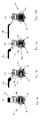
- the exposed area of the ball and its mating seal resemble a small "nail” or moon shape that widens dramatically with each degree of movement of the handle, as shown particularly in FIGS. 1B and 1C.
- the resulting intersecting area of the two round passages creates an unpredictable and extremely sensitive "exposed" area to fluid flow that often makes ball valves difficult to set for a desired flow rate.
- ball valves are often used to balance hydronic (heating ventilating and air conditioning or "HVAC") closed loop systems.
- HVAC heating ventilating and air conditioning
- the ball valves are often provided with built-in venturi and/or orifices to allow precise measurement of the flow rate through the ball valve.
- the standard configuration of a ball valve may not facilitate precise setting because of the sensitivity by degree of handle movement. Thus, it may take several passes on either side of the final actuator setting before a desired flow rate is achieved.
- ball valves have been provided with relatively small bore sizes to alleviate low flow settings. Although providing better volume control, these ball valves may create an undesirably high friction loss for systems that require high flow conditions when the valve is fully open.
- the passage of the ball valve may be provided with alternative bore openings in an attempt to improve throttling and control.
- Toyo Company of Japan distributes ball valves that have spherical balls with diamond-shaped bores.
- U.S. Patent No. 5,593,135 issued to Lester et al discloses a ball valve that has a plastic spherical ball with a cylindrical bore extending most of the way through the ball. At one end, however, the bore is partially closed by a throttling wall formed as part of the spherical ball.
- the throttling wall has an oblong opening therein for providing a more linear flow condition as the ball is rotated within the valve body.
- Such ball valves require uniquely cast or machined spherical balls for each desired flow condition or "C v offering.”
- diamond-shaped or other special port openings may not provide linear or other desired volumetric flow control for certain applications.
- the cost and difficulty in manufacturing such customized ball valves may be further exacerbated when they are machined or formed from conventional materials, such as brass or stainless steel.
- the present invention is directed to a ball valve and to an insert for a ball valve adapted to provide precise, substantially linear and/or equal percentage volumetric flow control of fluid flow through the ball valve.
- the present invention is also directed to a volume control insert and to a set of inserts for a ball valve for providing a variety of predetermined flow conditions.
- an insert device is provided that is attachable to a valving member in a ball valve for providing a predetermined flow condition through the ball valve.
- the insert device has a substantially convex shape corresponding to an outer surface of the valving member.
- a connector is disposed on a periphery of the insert device to attach it across a passage through the valving member.
- the insert device has an elongate slot, such as an oblong or parabolic shaped opening, through it that is adapted to provide the predetermined flow condition through the passage of the valving member.
- a versatile flow control device in another aspect of the present invention, includes a ball valve and a plurality of volume control inserts for providing a range of predetermined flow conditions through the ball valve.
- the ball valve has a valve housing with upstream and downstream passages extending into and out of a valve seat within the valve housing, thereby defining a longitudinal axis through the valve housing.
- a valving member with a bore extending through it, is rotatably mounted within the valve seat, such that the bore is alignable with the longitudinal axis.
- the bore and the upstream and downstream passages together define an adjustable fluid passage through the valve housing as the valving member is turned between full open and full closed positions.
- the plurality of inserts are individually attachable across the fluid passage, each of the inserts having an elongate opening therethrough adapted to provide a predetermined flow condition through the fluid passage.
- the valving member and each insert include a connector for attaching the insert to the valving member across the bore, such as cooperating legs and pockets.
- a ball valve that allows substantially linear volumetric flow control.
- the ball valve includes a valve housing having a passage extending through it along a longitudinal axis.
- a valving member having a bore extending through it, is seated in the valve housing, the bore being alignable with the passage.
- the valving member is rotatable about a transverse axis between open and closed positions, such that the bore and passage define a fluid passage adjustable between maximum and minimum flow rate conditions as the valving member is rotated between its open and closed positions respectively.
- the ball valve includes a volume control member extending substantially across the fluid passage that has a parabolic opening therethrough.
- the parabolic opening has a parabolic shape adapted to provide a substantially equal percentage flow characteristic between the maximum and minimum flow rate conditions when the valving member is rotated, i.e. by each degree of movement of the valving member between its open and closed positions.
- the volume control member is a volume control insert that is attachable across said fluid passage, such as that described above.
- a principal object of the present invention is to provide a volume control insert and a set of such inserts that may be selectively attached to a ball valve to provide a predetermined flow condition through the ball valve.
- FIGS. 1A through 1D are cross-sectional end views of a conventional ball valve, showing the spherical ball being moved between its full open and full closed positions.
- FIG. 2A is a cross-sectional view of a ball valve in accordance with the present invention.
- FIG. 2B is a front view of a volume control insert in accordance with the present invention.
- FIG. 2C is a partial cross-sectional view of an alternative embodiment of the ball valve of FIG. 2A.
- FIGS. 3A through 3D are cross-sectional end views of the ball valve of FIG. 2A, showing the valving member being moved between its full open and full closed positions.
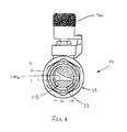
- FIG. 4 is an end view of a ball valve in accordance with the present invention having a parabolic opening across the fluid passage of the ball valve.
- FIGS. 5A through 5D are cross-sectional end views of the ball valve of FIG. 4.
- FIG. 6 is a cross-sectional view of an alternative embodiment of a ball valve in accordance with the present invention.
- FIG. 7 is a table comparing the flow characteristics of a conventional ball valve with ball valve openings in accordance with the present invention.
- FIG. 2A shows a ball valve 10 in accordance with the present invention.
- the ball valve 10 generally includes a valve housing 12, a valve seat 14, a valving member 16, and a volume control insert 18.
- the valve housing 12, which may be provided from conventional materials, has a cavity 20 for receiving the valve seat 14 and valving member 16, and a passage 22 extending axially in and out of the cavity 20 along the longitudinal axis 23.
- the passage 22 defines a conduit through which a fluid, such as conditioned air, may flow when the ball valve 10 is installed in a fluid delivery system, such as a hydronic HVAC system (not shown).
- the valve seat 14 is a sealing member for rotatably seating the valving member 16 within the cavity 20.
- the valve seat 14 provides a fluid-tight seal between an outer surface 38 of the valving member 16 and the valve housing 12, while allowing the valving member 18 to be rotated therein.
- the valve seat 14 is generally provided from conventional materials, such as plastic or compound plastic, and more preferably Teflon, and may be provided in a plurality of segments, such as upstream and downstream portions or upper and lower portions (not shown), which may be individually mounted in the cavity 20 to seat the valving member 16.
- the valving member 16 is generally a substantially spherical ball 24 having a cylindrical bore 26 extending axially therethrough.
- the cylindrical bore 26 generally has a diameter corresponding substantially to the diameter of the passage 22 extending through the valve housing 12.
- the spherical ball 24 also includes a pocket 28 within the bore 26 for securing the volume control insert 18, as explained further below.
- a plurality of pockets 28 are provided at predetermined locations about the periphery of the bore 26 adjacent one end thereof to detachably secure the volume control insert 18 in a predetermined orientation, although alternatively, the valving member 16 may include an annular groove (not shown) instead.
- the valving member 16 is generally formed from conventional ball valve materials that provide a durable device capable of withstanding the flow conditions and fluids encountered during its use.
- the valving member is machined from a metal, such as brass or stainless steel, thereby providing precise tolerances as compared to other processes such as casting.
- the valving member 16 may also be formed in alternative configurations, such as a cylindrical or frusto-conical shape, and/or using alternative methods of manufacturing as should be appreciated by those skilled in the art.
- the valving member 16 includes a valve stem 30 which extends from the valving member through a stem aperture 32 in the valve housing 12.
- the valve stem 30 is attached to the spherical ball 28 along a transverse axis 34 that is substantially perpendicular to the longitudinal axis 23.
- a handle 36 or alternatively an electric, hydraulic or other motorized actuator (not shown), is attached to the valve stem 30 to rotate the valving member 16 within the valve seat 14 and cavity 20.
- the ball valve 10 also includes a volume control insert 18 which is attachable across the bore 26 of the valving member 16.
- the volume control insert 18 is a disc-shaped member 40 having a diameter corresponding substantially to the diameter of the bore 26 of the valving member 16.
- the disc-shaped member 40 has a convex outer surface 42 corresponding substantially to the outer surface 38 of the valving member 16.
- the inner surface 44 may be substantially flat, as shown, or may have a concave shape (not shown) similar to the outer surface 42.
- the volume control insert 18 may have other shapes, such as a substantially rectangular shape (not shown).
- the volume control insert 18 should be small enough to be insertable into the passage 22, and its outer periphery should correspond substantially to the shape of the bore 26 at the location where the volume control insert 18 is to be attached to the valving member 16.
- a disk-shaped volume control insert 18 is preferred as it allows the valving member 16 to be made using generally conventional machining processes, rather than requiring specialized design and fabrication methods.
- the disc-shaped member 40 has a plurality of legs or tabs 48 for securing the volume control insert 18 to the valving member 16.
- the legs 48 are integrally formed on the periphery of the disc-shaped member 40 at predetermined locations corresponding to the pockets 28 in the valving member 16, and are resiliently deformable to facilitate attachment of the volume control insert 18 as described below.
- the disc-shaped member 40 may include an annular groove or tab (not shown) to correspond with a similar groove (not shown) in the valving member 16.
- one or more of the legs 48 may have a unique configuration, for example a larger size than the other legs, corresponding to a similarly configured pocket in the valving member 16 (not shown). This leg configuration may ensure proper alignment of the opening 46 in the volume control insert 18 within the bore 26.
- the disc-shaped member 40 may include an aligning tab 52 adapted to be received in a corresponding slot 54 in the valving member 16.
- the disc-shaped member 40 includes an elongate slot or opening 46 extending axially therethrough.
- the opening 46 has an oblong shape (see FIGS. 3A-3D), while in a second preferred embodiment, the opening 46 has a parabolic shape (see FIGS. 5A-5D).
- the opening 46 preferably extends along a plane substantially perpendicular to the transverse axis 34.
- the opening 46 has a predetermined width, height and cross-sectional shape adapted to provide a preselected flow condition, i.e. to provide precise volumetric control between a maximum flow rate when the valving member 16 is in its full open position, and a minimum flow rate (typically zero) when the valving member 16 is in its full closed position.
- the volume control insert 18 may be provided from a variety of conventional materials, such as plastic or metal, which may be formed using conventional processes. Injection molded plastics, such as are preferred, as they provide high tolerance inserts that may be efficiently manufactured. Such plastics also may ensure that the legs 48 are resiliently deflectable to facilitate attachment of the volume control insert 18.
- the legs 48 are preferably substantially rigid yet sufficiently flexible to compress as the volume control insert 18 is directed into the passage 22 and bore 26, and to resiliently snap into the pockets 28 to secure the volume control insert 18 in place.
- the legs 48 may also be sufficiently deflectable to facilitate the legs 48 being directed out of the pockets 28 with a tool (not shown), thereby allowing the volume control insert 18 to be detached from the valving member 16 without damaging any of the components of the ball valve 10.
- an assembled ball valve 10 without the volume control insert 18, is provided using conventional manufacturing processes.
- the ball valve 10 is substantially conventional in its appearance and manufacturing, with the exception of the connector, such as the pockets 28 and /or the groove 54 (FIG. 2C), which may be provided within the bore 26 of the valving member 16.
- the connector such as the pockets 28 and /or the groove 54 (FIG. 2C)
- a conventional ball valve 410 such as that shown in FIGS. 1A-1D, without a connector may be provided, and a connector may be formed in the valving member 416, for example by machining pockets therein (not shown).
- a set of volume control inserts such as the exemplary volume control insert 18 shown in FIG. 2A, may be provided.
- Each volume control insert 18 has a similar diameter or cross-section corresponding to bore 26 of the valving member 16.
- Each volume control insert 18, however, has a different opening 46, such as an oblong or parabolic opening, having a different width and height, that corresponds to a predetermined maximum flow condition.
- the set of volume control inserts may provide a variety of flow conditions, i.e. a predetermined range of volumetric flow rates between the full open and full closed positions, that may be selected by the user.
- a volume control insert 18 is selected from the set that provides a predetermined flow condition appropriate for the given application of the ball valve 10. With the valving member 16 in its full open position, the volume control insert 18 is directed into the passage 22.
- the opening 46 may be aligned along a plane normal to the transverse axis 34, for example by orienting an aligning member, such as an enlarged leg (not shown), on the volume control insert 18 with a corresponding enlarged pocket (not shown) in the valving member 16.
- the legs 48 may be compressed slightly as described above until the volume control insert 18 becomes coextensive with the pockets 28. The legs 48 then engage or snap into the pockets 28, securing the volume control insert 18 to the valving member 16 across the bore 26.
- the ball valve 10 may then be installed in a flow system, such as a closed loop HVAC system, and used to provide volumetric flow control, the flow control of the ball valve 10 being dependent upon the size and shape opening 46 of the selected volume control insert 18.
- a flow system such as a closed loop HVAC system
- FIGS. 3A through 3D a first preferred embodiment of a volume control insert 18 with a substantially oblong opening 146 is shown secured within a ball valve 10.
- the ball valve 10 is shown in its full open position, in which the oblong opening 146 extends substantially across the passage 22.
- the valving member 16 may be positioned at any position between those shown in FIGS. 3A and 3D, such as those shown in FIGS. 3B and 3C, thereby providing a selectable flow rate.
- the oblong opening 146 travels a linear distance along an arc defined by the periphery 38 of the valving member 16.
- the cross-section of the flow passage 22 is constricted in a substantially linear fashion as the valving member 16 is turned.
- the flow passage 422 of a conventional ball valve 410 experiences a sudden and dramatic throttling as the valving member 416 is rotated.
- This sensitivity may exacerbate setting the ball valve 410 at a desired flow rate because as the valving member 416 is turned, the precise position for the desired flow rate may be passed over quickly, thereby causing the ball valve 416 to be difficult to balance at the desired setting.
- a second preferred embodiment of the volume control insert 118 is shown that has a parabolic opening 246.
- the parabolic opening 246 is "parabolic" in that the height h of the opening 246 changes across its width w, unlike the oblong opening 146 which has a substantially constant height. Similar to the oblong opening 146 above, the parabolic opening 246 provides improved volume control over a conventional ball valve, and in particular provides an equal percentage flow characteristic which is preferred in automatic temperature control systems.
- the parabolic opening 246 and the oblong opening 146 provide improved volumetric flow control over conventional ball valves.
- the curves 60, 62 and 64 show the flow rate of a conventional ball valve opening, an oblong opening and a parabolic opening, respectively, between minimum (0) and maximum (1) flow conditions as a function of the stem position of the ball valve, i.e. as the valve is rotated between its full closed (0) and full open (1) positions.
- the opening 46 travels along an arc defined by the periphery 38 of the valving member 16. Because fluid flow is axial through the passage 22, this arc is effectively projected onto the cross-section of the passage 22 through the ball valve 10. Thus, as the valving member 16 is turned a particular degree of rotation, the passage 22 is not obstructed in a true linear fashion.
- the parabolic opening 246 more accurately compensates for the arcuate or nonlinear path traveled by the volume control insert 118 because the parabolic opening 246 provides a cross-section that projects across the passage 22 to obstruct the passage 22 in a substantially equal percentage fashion as the valving member 116 is turned a particular degree of rotation.
- the height h of the parabolic opening 246 may be determined mathematically based upon the diameter of the valving member 16 and the desired flow condition range.
- the parabolic opening 246 travels more perpendicularly to the axis of the passage 22, thereby throttling the passage 22 quickly.
- the passage 22 is throttled more slowly because the arc traveled by the opening 146 has become more tangential in relation to the longitudinal axis 23 (not shown in FIGS. 5A-5D) of the passage 22.
- the valving member of a conventional ball valve may have to be turned a larger angle to obtain a comparable rate of reduction in fluid flow through its passage.
- the parabolic opening 246 compensates for this by reducing the exposed cross-sectional area of the parabolic opening 246 as the valving member 16 is turned, thus providing substantially linear volumetric flow changes with each degree of rotation.
- FIG. 6 an alternative embodiment of a ball valve 310 in accordance with the present invention is shown that includes a valve housing 312, a valve seat 314, a valving member 316 and a volume control insert 318.
- the valve housing 312 is generally similar to that previously described, having a passage 322 extending in and out of a central cavity 320.
- the valving member 316 is preferably a conventional spherical ball 324 having a cylindrical bore 326 extending axially therethrough.
- the valving member 316 is rotatable about a transverse axis 334 within the valve housing 312 by a valve stem 330 and an actuator, such as the handle 336.
- the valve seat 314, rather than the valving member 316, is adapted to have the volume control insert 318 attached to it.
- the valve seat 314 includes a permanent portion 350 that is mounted within the cavity 320 to sealably seat the valving member 316 in the cavity 320.
- the volume control insert 318 may be attachable to the valve seat 314 and/or may form a portion of the valve seat 314 itself.
- the volume control insert 318 includes an opening 46, such as the oblong opening 146 or the parabolic opening 246 described above, and has a substantially concave inner surface 342 corresponding to an outer surface 338 of the valving member 316.
- the volume control insert 318 may be an attachable portion of the valve seat 314, as shown in FIG. 6.
- the valve housing 312 may include one or more pockets (not shown) about the periphery of the passage 22 for receiving one or more corresponding legs or other connector (not shown) on the volume control insert 318.
- its inner surface 342 preferably sealably engages the outer surface 338 of the valving member 318 to help seat the valving member 316 and to help provide a fluid-tight seal between the passage 322 and bore 326.
- the volume control insert may be attachable to the valve seat itself (not shown).
- the valve seat and volume control insert may be similar to that shown in FIG. 2A, except that they include cooperating connectors, such as legs and pockets, that allow the volume control insert to be secured to the valve seat, rather than to the valving member.
- a set of volume control inserts may be provided for a single ball valve.
- the set of inserts may provide a range of flow conditions that allow a user to select an insert that provides a predetermined flow condition for a particular application.
- the inserts may be easily attached to the ball valve, and optionally may be detached and replaced with a new insert as it wears out or as the flow conditions of the application change, without having to replace the entire ball valve.
- a single ball valve in accordance with the present invention may replace an entire inventory of individual ball valves, giving a user improved versatility and convenience.
- a ball valve in accordance with the present invention is manufactured using substantially conventional methods. There is no need to machine or mold a variety of customized valving members or individual ball valves to provide a range of volumetric flow conditions.
- an insert in accordance with the present invention generally includes an opening, such as an oblong or parabolic shaped opening, that provides improved and/or substantially linear volumetric flow control, unlike conventional ball valves.
- an opening such as an oblong or parabolic shaped opening, that provides improved and/or substantially linear volumetric flow control, unlike conventional ball valves.
Landscapes
- Engineering & Computer Science (AREA)
- General Engineering & Computer Science (AREA)
- Mechanical Engineering (AREA)
- Taps Or Cocks (AREA)
Applications Claiming Priority (2)
| Application Number | Priority Date | Filing Date | Title |
|---|---|---|---|
| US4946 | 1998-01-09 | ||
| US09/004,946 US5937890A (en) | 1998-01-09 | 1998-01-09 | Insert for flow throttling ball valves |
Publications (2)
| Publication Number | Publication Date |
|---|---|
| EP0928916A2 true EP0928916A2 (de) | 1999-07-14 |
| EP0928916A3 EP0928916A3 (de) | 2000-12-20 |
Family
ID=21713335
Family Applications (1)
| Application Number | Title | Priority Date | Filing Date |
|---|---|---|---|
| EP99100279A Withdrawn EP0928916A3 (de) | 1998-01-09 | 1999-01-08 | Einsatz für einen Strömungsdrosselkugelhahn |
Country Status (3)
| Country | Link |
|---|---|
| US (1) | US5937890A (de) |
| EP (1) | EP0928916A3 (de) |
| JP (1) | JPH11270711A (de) |
Cited By (11)
| Publication number | Priority date | Publication date | Assignee | Title |
|---|---|---|---|---|
| WO2002084187A1 (en) * | 2001-04-11 | 2002-10-24 | Frigoscandia Equipment Ab | Two-stage refrigeration system |
| RU2200890C2 (ru) * | 2001-04-09 | 2003-03-20 | Государственное предприятие "Красноярский машиностроительный завод" | Кран |
| EP1439339A1 (de) * | 2003-01-14 | 2004-07-21 | Fratelli Pettinaroli S.P.A | Kugelhahn |
| EP1528303A1 (de) * | 2003-10-31 | 2005-05-04 | Siral S.p.A. | Kugelventil für die Regelung und Mischung des Durchflusses |
| EP1698810A1 (de) * | 2004-12-17 | 2006-09-06 | Invensys Building Systems, Inc. | Vorrichtung und Verfahren für das Ersetzen der vorhandenen Auslöserzonenventile in einem Heizungs-, Lüftungs-, und Klimatisierungssystem durch einen Kugelhahn |
| EP1744086A1 (de) * | 2005-07-15 | 2007-01-17 | Immergas S.p.A. | Vorrichtung zur Regelung der Durchflussmenge einer in einem Kessel strömenden Flüssigkeit |
| EP1862712A1 (de) * | 2006-06-02 | 2007-12-05 | Emech Control Limited | Mischventil und Mischvorrichtung |
| ITVR20110223A1 (it) * | 2011-12-12 | 2013-06-13 | Renato Colombo | Struttura di valvola |
| EP2226536A4 (de) * | 2007-12-18 | 2014-03-26 | Guangzhou Sinro Fogang Controls Co Ltd | Kugel-steuerventile |
| CN104455525A (zh) * | 2014-11-14 | 2015-03-25 | 浙江中控流体技术有限公司 | 流量可调节球阀 |
| BE1026921B1 (fr) * | 2018-12-26 | 2020-07-28 | Safran Aero Boosters Sa | Vanne |
Families Citing this family (50)
| Publication number | Priority date | Publication date | Assignee | Title |
|---|---|---|---|---|
| US6039304A (en) * | 1998-05-26 | 2000-03-21 | Belimo Air Control (Usa) Inc. | Ball valve with modified characteristics |
| AU2383400A (en) * | 1998-12-23 | 2000-07-12 | Belimo Air Control (Usa) Inc. | Control valve with modified characteristics |
| US6276397B1 (en) * | 2000-06-12 | 2001-08-21 | Flow Design, Inc. | Apparatus and method for shaping fluid flow |
| US6450374B1 (en) * | 2000-11-20 | 2002-09-17 | Johnsondiversey, Inc. | High flow/low flow mixing and dispensing apparatus |
| US6910673B2 (en) * | 2002-01-28 | 2005-06-28 | Valve Teck, Inc. | Valve with calibrated flow orifice insert |
| ITBS20020046A1 (it) * | 2002-05-03 | 2003-11-03 | Enolgas Bonomi Spa | Valvola a sfera con misuratore di portata incorporato direttamente nella sfera |
| US6926249B2 (en) | 2002-06-28 | 2005-08-09 | Invensys Building Systems, Inc. | Precision modulating globe valve |
| US20040167726A1 (en) * | 2003-02-25 | 2004-08-26 | Rouss Gino James | Method of flow control |
| US20050127317A1 (en) * | 2003-12-11 | 2005-06-16 | Rebello Peter J. | Metering ball valve and method of determining fluid flow therethrough |
| US7219877B1 (en) | 2004-03-11 | 2007-05-22 | Mogas, Inc. | Continuous catalyst extraction valve with line cleaning feature |
| JP4523314B2 (ja) * | 2004-03-31 | 2010-08-11 | 株式会社山武 | 三方ボール弁 |
| EP1745247B1 (de) | 2004-04-23 | 2015-11-11 | Philip Morris Products S.a.s. | Aerosolgeneratoren und verfahren zur herstellung von aerosolen |
| RU2301695C2 (ru) * | 2004-08-10 | 2007-06-27 | Институт теплофизики экстремальных состояний Объединенного института высоких температур РАН | Выпускное сопло к газовому клапану |
| US20060065313A1 (en) * | 2004-09-30 | 2006-03-30 | Sebastiano Saleri | Regulator and mixer ball valve |
| US20060145115A1 (en) * | 2005-01-05 | 2006-07-06 | Chien-Hsing Lai | Throttle valve and piston ring thereof |
| US7111643B2 (en) * | 2005-01-26 | 2006-09-26 | Invensys Building Systems, Inc. | Flow characterization in a flowpath |
| DK200501640A (da) * | 2005-02-04 | 2006-08-05 | Frese As | Kugleventil til brug i varme- eller köleanlæg |
| ITBS20050076A1 (it) * | 2005-06-24 | 2006-12-25 | Enolgas Bonomi S P A | Valvola di intercettazione |
| US7802586B1 (en) * | 2005-09-15 | 2010-09-28 | Zurn Industries, Llc | Vacuum breaker |
| US7347408B2 (en) * | 2006-03-07 | 2008-03-25 | Griswold Controls Inc | High differential pressure, low torque precision temperature control valve |
| CA117324S (en) * | 2006-03-13 | 2008-04-02 | Giacomini Spa | Ball valve |
| ITMI20060740A1 (it) * | 2006-04-13 | 2007-10-14 | Vir Valvoindustria Ing Rizzio | Sfera per valvole e relativo metodo di produzione |
| US20080099712A1 (en) * | 2006-10-25 | 2008-05-01 | Honeywell International Inc. | Cartridge ball valve |
| RU2334148C1 (ru) * | 2006-11-07 | 2008-09-20 | Александр Павлович Андреев | Клапан регулирующий |
| US20090032762A1 (en) * | 2007-08-03 | 2009-02-05 | Mogas Industries, Inc. | Flow Control Ball Valve |
| US20100155642A1 (en) * | 2008-06-18 | 2010-06-24 | Victaulic Company | Offset Handle and Dual Connected Handle and Valves |
| US20110168934A1 (en) * | 2010-01-11 | 2011-07-14 | Greg Sisk | Ball valve for a tank trailer |
| US9163388B2 (en) * | 2010-01-12 | 2015-10-20 | Nichols-Ip Pllc | Water hammer prevention valve and method |
| ES2368233B1 (es) * | 2010-04-26 | 2012-09-10 | Rafael Alcaráz Sencianes | Llave para conducciones de suministro de agua. |
| US8555926B2 (en) * | 2010-08-31 | 2013-10-15 | Malcolm MacDuff | Supply manifold for hydronic system |
| ES2399701B1 (es) * | 2011-04-05 | 2013-12-12 | Rafael Alcaráz Sencianes | Llave de tres posiciones para suministros de agua. |
| FI124840B (fi) * | 2012-05-28 | 2015-02-13 | Metso Automation Oy | Kiinnitysrengas ja venttiili |
| USD686298S1 (en) * | 2012-09-14 | 2013-07-16 | Barksdale, Inc. | Integral valve-actuator |
| US9086154B2 (en) * | 2013-04-04 | 2015-07-21 | Hamilton Sundstrand Corporation | Ball shaft for a liquid coolant valve |
| DE202013009952U1 (de) | 2013-10-28 | 2013-11-20 | Hakan Gülay | Frauenunterhose mit der eine Frau im stehen urinieren kann |
| SE541043C2 (en) | 2015-08-28 | 2019-03-19 | Ab Somas Ventiler | A valve, a valve set and a method for modifying a valve |
| CA2948712C (en) * | 2015-10-06 | 2018-09-11 | Malcolm Macduff | Supply manifold with rotatable slider |
| US9643134B1 (en) * | 2016-07-12 | 2017-05-09 | Mazzei Injector Company, Llc | Proportionate automated blending system for aqueous mixtures |
| KR101879774B1 (ko) * | 2016-12-28 | 2018-07-18 | 동의대학교 산학협력단 | 유니버설 조인트의 윤활유 자동 공급장치 |
| DE102017108905A1 (de) * | 2017-04-26 | 2018-10-31 | Schaeffler Technologies AG & Co. KG | Kühlmittelventil |
| KR101987451B1 (ko) * | 2017-10-18 | 2019-06-11 | 세메스 주식회사 | 기판 지지부재 및 이를 포함하는 기판 처리 장치 |
| US10677363B2 (en) | 2018-02-13 | 2020-06-09 | Dale S. Cheney | Water hammer prevention valve and method |
| IT201800003489A1 (it) * | 2018-03-13 | 2019-09-13 | Effebi Spa | Guarnizione per una valvola a sfera e gruppo otturatore sferico comprendente la guarnizione |
| FI20185842A1 (fi) * | 2018-10-09 | 2020-04-10 | Vexve Oy | Sisäkekappale, virtauksensäätökuula, kuulaventtiili ja menetelmä |
| KR102102143B1 (ko) * | 2018-11-27 | 2020-04-21 | 우명배 | 유량 조절 밸브 |
| GB2591309B (en) * | 2020-01-23 | 2024-07-10 | Ntdrill Holdings Llc | Drilling choke with matched actuator |
| CN111637251A (zh) * | 2020-05-29 | 2020-09-08 | 上海化工院检测有限公司 | 一种定流量比例配气球阀 |
| US11754300B2 (en) * | 2020-09-16 | 2023-09-12 | Brent Michael Joseph Lamoureux | Direct room economizer |
| DE102021130800B3 (de) | 2021-11-24 | 2023-01-12 | Walther Systemtechnik Gmbh | Adaptiver Druckregler |
| CN120693221A (zh) | 2022-12-06 | 2025-09-23 | 阿尔伯茨集成管道系统美国股份有限公司 | 球阀、表征孔口插入件及其制造方法 |
Citations (1)
| Publication number | Priority date | Publication date | Assignee | Title |
|---|---|---|---|---|
| US5593135A (en) | 1995-05-12 | 1997-01-14 | Asahi/America, Inc. | Precise throttling ball valve |
Family Cites Families (23)
| Publication number | Priority date | Publication date | Assignee | Title |
|---|---|---|---|---|
| US915543A (en) * | 1908-11-03 | 1909-03-16 | Daniel Billiard | Expansion-valve. |
| US1175328A (en) * | 1914-07-17 | 1916-03-14 | Hiram T Rose Jr | Valve. |
| US1454222A (en) * | 1920-12-24 | 1923-05-08 | Percy L Palmer | Valve cock |
| US1622406A (en) * | 1925-11-24 | 1927-03-29 | Wilhjelm Christian | Valve |
| US1972151A (en) * | 1932-02-26 | 1934-09-04 | Crane Co | Controlled flow plug valve |
| US2115675A (en) * | 1937-10-08 | 1938-04-26 | North American Fibre Products | Flow regulator |
| US2707971A (en) * | 1949-09-15 | 1955-05-10 | Harper Wyman Co | Gas valve |
| US3146792A (en) * | 1963-12-11 | 1964-09-01 | William H Donnelly | Ball valve |
| US3386461A (en) * | 1965-07-02 | 1968-06-04 | Texaco Canadian Ltd | Multi-port orifice valve |
| US3542337A (en) * | 1968-07-29 | 1970-11-24 | Domer Scaramucci | Throttling valve with protected seals |
| GB1210858A (en) * | 1968-08-07 | 1970-11-04 | Saunders Valve Co Ltd | Improvements in fluid flow control devices |
| US3707161A (en) * | 1970-09-23 | 1972-12-26 | Douglas W Crawford | Variable choke valve |
| US4130128A (en) * | 1974-07-17 | 1978-12-19 | Fuji Photo Film Co., Ltd. | Ball valve with orifice |
| FR2334901A1 (fr) * | 1975-12-09 | 1977-07-08 | Legris France Sa | Perfectionnement aux robinets a tournant a portee de joint spherique |
| US4111392A (en) * | 1976-07-06 | 1978-09-05 | Braukmann Armaturen Ag | Valve, especially a radiator valve |
| US4111229A (en) * | 1977-04-01 | 1978-09-05 | Christian Timothy T | Controlling the fluid in a ball valve |
| US4226263A (en) * | 1978-08-14 | 1980-10-07 | Valve Concepts International | Erosion control trim in a control mechanism for a ball valve |
| NO166419C (no) * | 1988-10-14 | 1991-07-31 | Norske Stats Oljeselskap | Kuleventil. |
| FI81895C (fi) * | 1988-12-30 | 1990-12-10 | Neles Oy | Reglerventil. |
| US5074522A (en) * | 1991-03-11 | 1991-12-24 | Worcester Controls Corporation | Ball valve having improved inherent rangeability |
| DE4115101A1 (de) * | 1991-05-08 | 1992-11-12 | Total Feuerschutz Gmbh | Dosierventil fuer schaummittel |
| FR2693248B1 (fr) * | 1992-07-03 | 1994-09-23 | Roger Bey | Vanne du type à bille ou à boisseau équipé d'un insert. |
| US5551467A (en) * | 1995-08-11 | 1996-09-03 | H-Tech, Inc. | Ball valve with controlled flow variation |
-
1998
- 1998-01-09 US US09/004,946 patent/US5937890A/en not_active Expired - Fee Related
-
1999
- 1999-01-08 EP EP99100279A patent/EP0928916A3/de not_active Withdrawn
- 1999-01-11 JP JP388599A patent/JPH11270711A/ja active Pending
Patent Citations (1)
| Publication number | Priority date | Publication date | Assignee | Title |
|---|---|---|---|---|
| US5593135A (en) | 1995-05-12 | 1997-01-14 | Asahi/America, Inc. | Precise throttling ball valve |
Cited By (12)
| Publication number | Priority date | Publication date | Assignee | Title |
|---|---|---|---|---|
| RU2200890C2 (ru) * | 2001-04-09 | 2003-03-20 | Государственное предприятие "Красноярский машиностроительный завод" | Кран |
| WO2002084187A1 (en) * | 2001-04-11 | 2002-10-24 | Frigoscandia Equipment Ab | Two-stage refrigeration system |
| EP1439339A1 (de) * | 2003-01-14 | 2004-07-21 | Fratelli Pettinaroli S.P.A | Kugelhahn |
| EP1528303A1 (de) * | 2003-10-31 | 2005-05-04 | Siral S.p.A. | Kugelventil für die Regelung und Mischung des Durchflusses |
| EP1698810A1 (de) * | 2004-12-17 | 2006-09-06 | Invensys Building Systems, Inc. | Vorrichtung und Verfahren für das Ersetzen der vorhandenen Auslöserzonenventile in einem Heizungs-, Lüftungs-, und Klimatisierungssystem durch einen Kugelhahn |
| US7367544B2 (en) | 2004-12-17 | 2008-05-06 | Tac, Llc | Apparatus and method for replacing existing actuator zone valves in an HVAC system with a ball valve |
| EP1744086A1 (de) * | 2005-07-15 | 2007-01-17 | Immergas S.p.A. | Vorrichtung zur Regelung der Durchflussmenge einer in einem Kessel strömenden Flüssigkeit |
| EP1862712A1 (de) * | 2006-06-02 | 2007-12-05 | Emech Control Limited | Mischventil und Mischvorrichtung |
| EP2226536A4 (de) * | 2007-12-18 | 2014-03-26 | Guangzhou Sinro Fogang Controls Co Ltd | Kugel-steuerventile |
| ITVR20110223A1 (it) * | 2011-12-12 | 2013-06-13 | Renato Colombo | Struttura di valvola |
| CN104455525A (zh) * | 2014-11-14 | 2015-03-25 | 浙江中控流体技术有限公司 | 流量可调节球阀 |
| BE1026921B1 (fr) * | 2018-12-26 | 2020-07-28 | Safran Aero Boosters Sa | Vanne |
Also Published As
| Publication number | Publication date |
|---|---|
| JPH11270711A (ja) | 1999-10-05 |
| US5937890A (en) | 1999-08-17 |
| EP0928916A3 (de) | 2000-12-20 |
Similar Documents
| Publication | Publication Date | Title |
|---|---|---|
| US5937890A (en) | Insert for flow throttling ball valves | |
| US20010030309A1 (en) | Control valve with modified characteristics | |
| CA1257524A (en) | Mixing cartridge for hot and cold water faucets | |
| US20060172681A1 (en) | Air vent, in particular for a vehicle | |
| CA2193788A1 (en) | Valve interchangeable between angle and straight | |
| US4815493A (en) | Cartridge bypass valve | |
| US7059584B2 (en) | Diaphragm valve having adjustable closure means | |
| JPS6095288A (ja) | 暖房器用弁 | |
| CA2338441C (en) | Ball valve | |
| US20250198532A1 (en) | Control Valve | |
| JP3043664B2 (ja) | 混合弁及び混合弁用ボール弁 | |
| US20050127317A1 (en) | Metering ball valve and method of determining fluid flow therethrough | |
| US4830277A (en) | Thermostatic valve | |
| CN101835646A (zh) | 送风装置 | |
| US20040000654A1 (en) | Precision modulating globe valve | |
| EP1744085A1 (de) | Ventilspindel | |
| JP3202602B2 (ja) | 流体定量装置および該装置を備えた圧縮空気潤滑装置 | |
| KR890000449B1 (ko) | 유체 조절 밸브 | |
| US3561728A (en) | Fluid control valves | |
| JP2001099338A (ja) | 逆止弁 | |
| US12584562B2 (en) | Flow restrictor | |
| CA2449372C (en) | Cylindrical plug valve | |
| US20010008277A1 (en) | Ball valve | |
| US3773080A (en) | Air flow control valve | |
| EP0461294A1 (de) | Absperrventil |
Legal Events
| Date | Code | Title | Description |
|---|---|---|---|
| PUAI | Public reference made under article 153(3) epc to a published international application that has entered the european phase |
Free format text: ORIGINAL CODE: 0009012 |
|
| AK | Designated contracting states |
Kind code of ref document: A2 Designated state(s): AT BE CH CY DE DK ES FI FR GB GR IE IT LI LU MC NL PT SE |
|
| AX | Request for extension of the european patent |
Free format text: AL;LT;LV;MK;RO;SI |
|
| PUAL | Search report despatched |
Free format text: ORIGINAL CODE: 0009013 |
|
| AK | Designated contracting states |
Kind code of ref document: A3 Designated state(s): AT BE CH CY DE DK ES FI FR GB GR IE IT LI LU MC NL PT SE |
|
| AX | Request for extension of the european patent |
Free format text: AL;LT;LV;MK;RO;SI |
|
| RIC1 | Information provided on ipc code assigned before grant |
Free format text: 7F 16K 5/06 A, 7F 16K 5/12 B |
|
| 17P | Request for examination filed |
Effective date: 20010620 |
|
| AKX | Designation fees paid |
Free format text: AT BE CH CY DE DK ES FI FR GB GR IE IT LI LU MC NL PT SE |
|
| STAA | Information on the status of an ep patent application or granted ep patent |
Free format text: STATUS: THE APPLICATION HAS BEEN WITHDRAWN |
|
| 18W | Application withdrawn |
Withdrawal date: 20021024 |