EP0929057A2 - Steuerungssystem und Übertragungsverfahren - Google Patents
Steuerungssystem und Übertragungsverfahren Download PDFInfo
- Publication number
- EP0929057A2 EP0929057A2 EP99300129A EP99300129A EP0929057A2 EP 0929057 A2 EP0929057 A2 EP 0929057A2 EP 99300129 A EP99300129 A EP 99300129A EP 99300129 A EP99300129 A EP 99300129A EP 0929057 A2 EP0929057 A2 EP 0929057A2
- Authority
- EP
- European Patent Office
- Prior art keywords
- information
- transmission message
- units
- unit
- addressee
- Prior art date
- Legal status (The legal status is an assumption and is not a legal conclusion. Google has not performed a legal analysis and makes no representation as to the accuracy of the status listed.)
- Withdrawn
Links
Images


Classifications
-
- G—PHYSICS
- G08—SIGNALLING
- G08B—SIGNALLING SYSTEMS, e.g. PERSONAL CALLING SYSTEMS; ORDER TELEGRAPHS; ALARM SYSTEMS
- G08B26/00—Alarm systems in which substations are interrogated in succession by a central station
- G08B26/001—Alarm systems in which substations are interrogated in succession by a central station with individual interrogation of substations connected in parallel
Definitions
- This invention relates to a control system and a transmission method, and more particularly to a control system and a transmission method which are suitable for a disaster preventing system or the like.
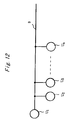
- a control system for a disaster preventing system or the like which is conventionally known in the art is constructed in such a manner as shown in Fig. 12 by way of example. More specifically, the control system shown in Fig. 12 includes a controller unit U 1 and various units to be controlled (hereinafter referred to as "controlled units") U 2 to U n commonly connected to the controller unit U 1 . In such a control system, a transmission message based on a communication control protocol is used for exchange of information between the controller unit U 1 and the respective controlled units U 2 to U n .
- a transmission message used for such a control system is constructed as shown in Fig. 13(a) by way of example. More particularly, the transmission message is constituted by a header, an address (an address of an addressee), a command, data, and a checksum.
- the controlled units which are units on a receive side (hereinafter referred to as "receive side units") each compare an address set in itself with the address contained in the transmission message or the address of the addressee. As a result, when both are coincident with each other, the latter address is judged to be a transmission message for the controlled unit itself, so that the controlled unit takes in it and then carries out processing thereof depending on a command contained in the transmission message.
- a transmission message shown in Fig. 13(b) may be substituted for that shown in Fig. 13(a).
- the transmission message shown in Fig. 13(b) includes type data in addition to a transmission message of such a type as shown in Fig. 13(a).
- checksum> ⁇ Header> EXOR ⁇ Address> EXOR ⁇ Type> EXOR ⁇ Command> EXOR ⁇ Data>
- the controlled units or the receive side units each compare an address set in itself with an address contained in the transmission message or an address of the addressee. As a result, when both are coincident with each other, the controlled unit judges that the latter address is a transmission message addressed to itself. Also, it judges whether or not the transmission message is necessary, on the basis of type data in the transmission message. As a result, only when it is judged to be necessary, the controlled unit takes in the transmission message, to thereby carry out processing depending on a command contained in the transmission message.
- the commands include, for example, "a command for collecting data from the controlled units (receive side units)", "a command for sending a control signal which provides the controlled units (receive side units) with predetermined information (for example, an alarm)", "a command for carrying out automatic test of the controlled units (receive side units)” or the like.
- the command contained in the transmission message from the controller unit U 1 is "a command for collecting data from the controlled units”
- the controlled unit by which the transmission message has been taken in is adapted to return data collected according to the command of the transmission message such as, for example, data on fire detection to the controller unit U 1 .
- the transmission message from the controller unit U 1 contains "a control signal (control data)which provides the controlled units (receive side units) with predetermined information (for example, an alarm)” or "test control data for carrying out automatic test of the controlled units (receive side unit)” as data therefor.
- control data control data which provides the controlled units (receive side units) with predetermined information (for example, an alarm)
- test control data for carrying out automatic test of the controlled units (receive side unit)
- data in the transmission message are employed or taken in by the controlled units and then subject to processing in the controlled unit according to the command in the transmission message and on the basis of the data contained in the transmission message. Then, the controlled unit returns data on a result of the processing to the controller unit U 1 .
- the data on a result of the processing include, for example, data to the effect that an alarm has been displayed and data on a test result.
- the transmission message has data added thereto as required. Therefore, addition of data thereto is not necessarily carried out.
- ⁇ Data> are excluded from calculation of the checksum by each of the expressions (1) and (2) described above.
- the present invention has been made in view of the foregoing disadvantage of the prior art.
- a control system for carrying out exchange of information by means of a transmission message between a plurality of units.
- the units each have inherent ID information allocated thereto and the transmission message includes at least address information of an addressee and an operation code, wherein the operation code is calculated in consideration of at least ID information of the addressee.
- the operation code is calculated in the form of a checksum of at least the address information of the addressee and the ID information of the addressee.
- the units each are provided with a non-volatile memory, wherein the non-volatile memory of each of the units has ID information which is allocated for each of the units set therein.
- the non-volatile memory of each of the units is a one-time non-volatile memory.
- the one-time non-volatile memory is constructed so as to permit writing of the ID information thereto only one time.
- the unit of the addressee compares an operation code in the transmission message received thereby with its own ID information to judge whether or not it is a transmission message addressed thereto.
- the ID information allocated to each of the units is set to be the same between the units which are intended to carry out exchange of information by means of the transmission message.
- a transmission method which is adapted to carry out exchange of information by a transmission message between units.
- the transmission method includes the steps of allocating inherent ID information to each of the units and incorporating at least address information of an addressee and an operation code into the transmission message when the transmission message is to be transmitted from a unit of an addresser to a unit of the addressee.
- the operation code is calculated in consideration of at least ID information of the addressee.
- the transmission method further includes the steps of letting the unit of the addressee judge whether or not address information in the transmission message received thereby is coincident with its own address when the transmission message is transmitted from the unit of the addresser to the unit of the addressee and letting the unit of the addressee compare an operation code contained in the transmission message received thereby with its own ID information to judge whether or not its own ID information is designated one, whereby when it is judged that the address information is coincident with the address of the unit of the addressee and the ID information of the unit of the addressee is designated one, the transmission message is judged to be a transmission message addressed to the unit of the addressee.
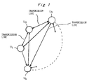
- a control system of the illustrated embodiment is constructed so as to permit a plurality of units U 1 to U n to carry out mutual exchange of information through transmission lines.
- the units U 1 to U n may be mutually homogeneous.
- the units U 1 to U n each may be constructed so as to function as a controller unit for each of the remaining units, as well as a controlled unit for each of the remaining units.
- a controller unit for each of the remaining units
- a controlled unit for each of the remaining units Alternatively, as shown in Fig.
- the units U 1 to U n may be so constructed that one of them (for example, the unit U 1 ) acts as a controller unit and another part of the units (for example, each of the units U 2 to U n ) acts as a controlled unit for the controller unit U 1 .
- a transmission message of the type shown in Fig. 13(a) is constituted of a header, an address of an addressee, a command, data and a checksum.
- a transmission message of the type shown in Fig. 13(b) includes type data in addition to the transmission message of the type shown in Fig. 13(a).
- the checksum is added to the transmission message for the purpose of enhancing or increasing reliability in communication of the transmission message.
- the ID information may include, for example, a code peculiar to a manufacturer of the units, a code indicating an agency, a code required for enhancing security in exchange of information, or the like.
- this embodiment principally or basically employs a transmission message of the type similar to that shown in Fig. 13(a) or 13(b), however, the checksum has the ID information of the addressee added thereto or embedded therein while considering it; so that a receive side unit (a unit of the addressee) may use the checksum to judge whether or not ID information coincident with its own ID information is designated.
- the transmission message may be taken in only by the receive side unit which has an address coincident with the address of the addressee contained in the transmission massage and possesses ID information coincident with the ID information embedded in the checksum.
- the receive side unit when it does not include ID information identical with that embedded in the checksum although it includes an address coincident with the address of the addressee contained in the transmission message, it fails to take in the transmission message. This highly enhances or increases security in exchange of the transmission message between the units.
- This embodiment permits the transmission message to be principally or basically constructed in substantially the same manner as shown in Fig. 13(a) or 13(b) even when ID information is further considered.
- the transmission message is formed into the same length as that of the type shown in Fig. 13(a) or 13(b). This permits the transmission message to be kept from being increased in length, to thereby effectively prevent a deterioration in transmission efficiency of the transmission message due to addition of the ID information thereto.
- control system shown in Fig. 1 permits units maximum in number of addresses which correspond in number to ID information to be connected to a single transmission line.
- FIG. 2 one example of the control system shown in Fig. 1 is illustrated.
- a control system shown in Fig 2 is so constructed that a part of units, for example, a unit U 1 acts as a controller unit and another part thereof, for example, each of units U 2 to U n acts as a controlled unit.
- the control system shown in Fig. 2 includes one such controller unit U 1 and a plurality of the controlled units U 2 to U n commonly connected to a transmission line 3 as in the control system shown in Fig. 12, so that exchange of information by a transmission message may be carried out between the single controller U 1 and each of the controlled units U 2 to U n .
- Fig. 3 shows another example of the control system shown in Fig. 1.
- a control system of Fig. 3 is likewise constructed so that a part of units acts as a controller unit and another part thereof acts as a controlled unit. More specifically, a single controller unit U i1 and a plurality of controlled units U i2 to U in in a combination are commonly connected to a transmission line 3.
- the transmission line 3 also has another combination of a controller unit U j1 and a plurality of controlled units U j2 to U jm connected thereto.
- the controller unit U i1 and a plurality of the controlled units U i2 to U in are connected in the lump to the transmission line 3 and likewise the controller unit U j1 and a plurality of the controlled units U j2 to U jm are connected in the lump to the transmission line 3.
- the controller unit U i1 , a plurality of the controlled units U i2 to U in , the controller unit U j1 , a plurality of the controlled units U j2 to U jm are connected to the transmission line 3 in any random manner.
- the controller units U 1 , U i1 and U j1 respectively shown in Figs. 2 to 4 each may be constructed in such a manner as shown in Fig. 5.
- the controller of Fig. 5 represented by, for example, the controller unit U 1 generally includes a central processing unit 11, a memory section 12, a console section 13, a display section 14 and a communication control section 15.
- the memory section 12 may be constituted of, for example, a read only memory (ROM).
- the memory section 12 has a program for the central processing unit 11, ID information allocated to the controller unit U 1 and the like stored therein.
- the program for the central processing unit 11, when the control system is, for example, a disaster preventing system, may be a processing program required for disaster preventing control, a processing program required for carrying out monitor and control of the controlled units, or the like.
- the display section 14 is adapted to display a fire alarm or the like, when the control system is, for example, a disaster preventing system and a disaster such as, for example, fire or the like is detected in any of the controlled units.
- the communication control section 15 is constructed so as to carry out communication of information through the transmission line 3 between the communication control section 15 and the controlled units, as well as control of the communication.
- the communication control section 15 When the communication control section 15 is to transmit information to the controlled units, it produces a transmission message of such a type as shown in Fig. 13(a) or 13(b) which has a checksum in which ID information for a controlled unit of an addressee is embedded. Then, the communication control section 15 transmits it to the controlled unit.
- the communication control section 15 when the controlled unit returns the transmission message to the communication control section 15 after the communication control section 15 transmits the transmission message to the controlled unit, receives the returned transmission message to give information contained in the transmission message to the central processing unit 11. This results in the central processing unit 11 carrying out predetermined processing. For example, when fire detection data or the like are contained in the transmission message returned from the controlled unit, the central processing unit 11 carries out fire alarm processing or the like.
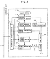
- each of the controlled units represented by, for example, the controlled unit U 2 generally includes a transmission interface section 21, a memory section 22, a sensor 23, a signal processing circuit 24, a unique address setting section 25, an address comparison section 26, a checksum operation section 27, an error detection section 28, an AND circuit 29 and a command discriminating seciton 30.
- the transmission interface section 21 functions to carry out exchange of information between the transmission interface section 21 and the controller unit U 1 .
- the transmission interface section 21 when it receives a transmission message from the controller unit U 1 , provides the address comparison section 26, command discriminating seciton 30, signal processing circuit 24 and checksum operation section 27 with an address, a command, data and a checksum each contained in the transmission message, respectively.
- the transmission interface section 21, when it is to return information (return data) to the controller unit U 1 produces a transmission message of such a type as shown in Fig. 13(a) or 13(b) which has a checksum in which ID information for the controller unit U 1 is embedded.
- the transmission message may be, for example, a transmission message having a checksum calculated according to an expression (5) described hereinafter. Then, the transmission interface section 21 transmits the thus-produced transmission message to the controller unit U 1 . It is not necessarily required that the transmission message to be transmitted from the controlled unit to the controller unit U 1 is prepared as shown in Fig. 13(a) or 13(b). For example, the transmission message to be transmitted from the controlled unit to the controller unit U 1 may be the transmission message of Fig. 13(a) or 13(b) except that it is not necessarily required to contain an address (an address for the controller unit U 1 ) and a command.
- the memory section 22 of the controlled unit may be constituted of a non-volatile memory such as an EPROM, a fuse memory or the like.
- the memory section 22 is previously stored therein with ID information allocated to the controlled unit U 2 .
- the unique address setting section 25 has an address inherent(unique) to the controlled unit U 2 preset therein.
- the address comparison section 26, when the transmission message is transmitted from the controller unit U 1 through the transmission line 3 to the controlled unit U 2 , carries out comparison between an address of an addressee contained in the transmission message and the address set in the unique address setting section 25. As a result, when both addresses are identical with each other, the address comparison section 26 outputs a logical value "1".
- the checksum operation section 27 takes an exclusive OR (EXOR) between the checksum contained in the transmission message and ID information stored in the memory section 22 of the controlled unit U 2 , when it receives the transmission message.
- EXOR exclusive OR
- results of the exclusive OR are all "0"
- the error detection section 28 when the above-described results of the exclusive OR from the checksum operation section 27 are all "0”, judges that there is no error or that the ID information embedded in the transmission message from the controller unit U 1 is coincident with the ID information of the controlled unit U 2 , resulting in outputting "1".
- the command discriminating section 30 is adapted to identify a command contained in the transmission message when it receives the transmission message. For this purpose, when an output of the address comparison section 26 is "1", an output of the error detection section 28 is “1" and an output of the AND circuit 29 is "1"; the command discriminating section 30 functions to identify the command to provide it with the signal processing circuit 24, which executes the command.
- the commands contained in the transmission message from the controller unit U 1 include, for example, "a command for collecting data from the sensor 23", "a command for providing the sensor 23 with a control signal for permitting it to display predetermined information (for example, an alarm)", "a command for carrying out automatic testing of the sensor 23” or the like.
- the command contained in the transmission message from the controller unit U 1 is "the command for collecting data from the sensor 23”
- the transmission message from the controller unit U 1 is not required to contain any data therein.
- the signal processing circuit 24 of the controlled unit which has taken in the transmission message takes in or collects data from the sensor 23 according to the command identified by the command discriminating section 30 and then returns the collected data through the transmission interface section 21 to the controller unit U 1 while using such a transmission format as described above.
- the data from the sensor 23 are in the form of analog data when the sensor 23 is of the analog type and in the form of digital data when it is of the digital type.
- the transmission message from the controller unit U 1 is required to contain "a control signal (control data) for displaying the alarm” or "test control data for carrying out automatic test of the sensor 23" as data therefor.
- the data contained in the transmission message are taken in by the signal processing circuit 24 of the controlled unit and then outputted in the form of a control output signal DO to the sensor 23 according to the command identified by the command discriminating section 30. This results in processing operation being carried out in the sensor 23 on the basis of the thus-outputted control output signal DO.
- the sensor 23 outputs data indicating results of the processing to the signal processing circuit 24.
- the data outputted from the sensor 23 are in the form of analog data AI when the sensor 23 is of the analog type and in the form of digital data DI when it is of the on-off type.
- the signal processing circuit 24 takes in or collects the data outputted from the sensor 23 and then returns the collected data through the transmission interface section 21 to the controller unit U 1 while using such a transmission format as described above.
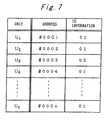
- FIG. 7 an address and ID information set in each of the units U 1 to U n in the control system of Fig. 1 represented by, for example, the control system of Fig. 2 are illustrated.
- the controller unit U 1 when it transmits the transmission message to each of the controlled units U 2 to U n , transmits it in consideration of an address and ID information for a controlled unit. For example, in Fig.
- the transmission message from the controller unit U 1 may be taken in by the units U 2 and U 4 to U n (and more specifically, of the units U 2 and U 4 to U n , the unit having its own address coincident with the address contained in the transmission message), but cannot be taken in by the unit U 3 different in ID information.
- control system of the illustrated embodiment highly enhances security in exchange of information.
- ID information for example, "01” can be set in the controller unit U i1 and plural controlled units U i2 to U in
- ID information for example, "02” which is different from the ID information ("01") set in the controller unit U i1 and plural controlled units U i2 to U in can be set in the controller unit U j1 and plural controlled units U j2 to U jm .
- the transmission message from the single controller unit U i1 may have the ID number "01" which is allocated to the controlled units U i2 to U in set as an ID number therefor. This permits the transmission message from the controller unit U i1 to be taken in only any one of the controlled units U i2 to U in and keeps from being taken in by the other controller unit U j1 and controlled units U j2 to U jm .
- the transmission message from the single controller unit U j1 may have the ID number "02" which is allocated to the controlled units U j2 to U jm set as an ID number therefor. This permits the transmission message from the controller unit U j1 to be taken in only any one of the controlled units U j2 to U jm and keeps from being taken in by the other controller unit U i1 and controlled units U i2 to U in .
- the ID information is considered in the transmission message to enhance security in exchange of information between the units.
- the above-described ID information is assigned as customer's data to a sensor in which a transmission function for mass production is incorporated, so that a customer's controller may be restricted to only communication with an approved sensor, to thereby ensure reliability of a whole system. This, when any coarse sensor is connected to the controller, effectively prevents exchange of information between the coarse sensor and the controller.
- Fig. 2 it is supposed that an address and ID information of each of the units U 1 to U n are set as shown in Fig. 7. More particularly, in Fig. 7, addresses of the units U 1 to U n are set to be different from each other. Also, ID information is set to be "01" in each of the units U 1 , U 2 and U 4 to U n and "02" in the unit U 3 which is different from "01".
- the controller unit U 1 when the controller unit U 1 is to let the controlled unit U 2 carry out predetermined processing by way of example, the controller unit U 1 prepares a transmission message addressed to the controlled unit U 2 . More specifically, the transmission message prepared includes a header, an address (#0002) of the controlled unit U 2 , a command, data as required, and a checksum in which ID information "01" is embedded. Then, the transmission message is outputted through the communication control section 15 to the transmission line 3.
- the controlled units U 2 to U n connected to the transmission line 3 each receive the transmission message transmitted from the controller unit U 1 through the transmission line 3 thereto and then judges whether or not the address (#0002) contained in the transmission message is coincident with a unique address set in itself and whether or not the ID information ("01") in the checksum is coincident with ID information set in itself.
- the controlled units U 2 to U n only the controlled unit U 2 has an address coincident with the address (#0002) and also has ID information coincident with the ID information "01", so that the transmission message is taken or collected in by only the controlled unit U 2 , resulting in processing indicated by the command of the transmission message being executed in the controlled unit U 2 .
- Results of the processing in the controlled unit U 2 may be returned in the form of a transmission message from the transmission interface 21 through the transmission line 3 to the controller unit U 1 .
- the controlled unit U 2 carries out processing according to the transmission message from the controller unit U 1 ; so that when data are inputted from the sensor 23 of the controlled unit U 2 to the signal processing circuit 24, the signal processing circuit 24 gives the return data to the checksum operation section 27.
- the checksum operation section 27 calculates a checksum constituted by the ID information "01" of the controller unit U 1 , the address (#0001) of the controller unit U 1 and the return data according to, for example, the expression (5).
- Results of the calculation are sent to the transmission interface 21, so that the transmission interface 21 prepares a tramsmission message including a checksum (in which the ID information "01" of the controller unit U 1 is embedded) from the checksum operation section 27 as well as the address (#0001) of the controller unit U 1 and the return data, and returns this transmission message through the transmission line to the controller unit U 1 .
- a checksum in which the ID information "01" of the controller unit U 1 is embedded
- the controller unit U 1 prepares a transmission message addressed to, for example, the controlled unit U 3 .
- the controller unit U 1 prepares a transmission message constituted by a header, an address (#0003) of the controlled unit U 2 , a command, data as required, and a checksum in which ID information "01" is embedded. Then, the transmission message thus prepared is outputted through the communication control section 15 to the transmission line 3.
- the controlled units U 2 to U n connected to the transmission line 3 each receive the transmission message transmitted from the controller unit U 1 through the transmission line 3 thereto and then judges whether or not the address (#0003) contained in the transmission message is coincident with a unique address set in itself and whether or not the ID information ("01") in the checksum is coincident with ID information set in itself.
- the controlled unit U 3 has an address coincident with the address (#0003).
- the controlled unit U 3 has ID information of "02" rather than "01", which is not coincident with the ID information "01”, so that the controlled unit U 3 fails to take in the transmission message.
- the exclusive OR (EXOR) is used for operation of the checksum and operation as to coincidence of the ID information.
- each of the operations is not restricted to the exclusive OR (EXOR). Any other suitable rule such as addition and subtraction of data or the like may be employed for this purpose.
- the same ID information (for example, "01") is set in the units between which exchange of information is allowed.
- ID information of types different from each other may be set in the units between which exchange of information is allowed. In this instance, it is required to previously recognize (confirm) ID information for each of the units between which exchange of information is allowed.
- the illustrated embodiment permits the checksum of the transmission message to be properly recognized and only contents of a message of proper ID information to be taken in and processed by the controller unit, resulting in processing efficiency being significantly increased. Therefore, only a proper message contributes to exchange of information between the controller unit and the controlled unit, to thereby improve processing efficiency in each of the controller unit and controlled units.
- the transmission message contains the checksum.
- the checksum may be taken as an operation code in a broad sense.
- the checksum can be used as one of the various aspects of the operation code.
- the checksum as employed in the constructions described above may be used as the operation code.
- an initial value for a generative polynomial for cyclic redundancy check (CRC), or any other suitable code may be used as the operation code.
- the ID information per se may be used as the operation code.
- control system of the illustrated embodiment permits exchange of message to be carried out between the units by means of the transmission message.
- the units each have an inherent ID information assigned thereto and the transmission message contains at least the address information of the addressee, the command and the operation code, and the operation code is calculated on the basis of at least the ID information of the addressee (or the ID information of the addressee is embedded in the operation code).
- the checksum of at least the address information of the addressee, the command and the ID information of the addressee may be used as the operation code.
- the ID information of the addressee per se may be used as the operation code.
- the memory sections 12 and 22 of the units each may be constituted by a non-volatile memory.
- the non-volatile memory for each of the units may be preferably constructed so as to permit writing of the ID information only one time.
- a memory which permits writing of the non-volatile memory only one time is preferably used as the non-volatile memory because it further enhances security in exchange of information.
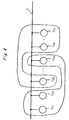
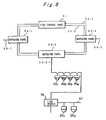
- the disaster preventing system includes a fire control panel 51, as well as repeater panels (in the illustrated example, three repeater panels 52-1 to 52-3) connected through main transmission lines 53-1 and secondary transmission lines 53-2 to the fire control panel 51.
- the repeater panels 52-1 to 52-3 have analog-type sensors and/or line modules connected thereto through transmission lines 56-1 to 56-3, respectively.
- the repeater panel 52-2 has analog-type sensors AS 1 to AS 4 and a line module 54 connected thereto through the transmission line 56-2.
- the line module 54 has on-off sensors DS 1 to DS 2 connected thereto through a transmission line 57.
- the fire control panel 51, the repeater panels (represented by the repeater panel 52-2 by way of example), and the analog-type sensors (represented by the analog-type sensor AS 1 by way of example) may be constructed as shown in Figs. 9, 10 and 11, respectively.
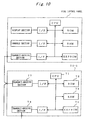
- a CPU 61 for controlling the whole fire control panel 51
- a ROM 62 having a control program for the CPU 61 and the like stored therein
- a RAM 63 acting as a work area for the CPU 61
- an EEPROM 64 in which ID information of the fire control panel 51 and the like are set
- a display section 65 for controlling the whole fire control panel 51
- a console section 66 for controlling the transmit-receive section 67
- a transmit-receive section 67 for permitting transmit-receive (or exchange) of information to be carried out between the transmit-receive section 67 and the repeater panels 52-1 to 52-3.
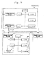
- Each of the repeater panels (represented by the repeater panel 52-2 by way example), as shown in Fig. 10, includes a CPU 71 for controlling the whole repeater panel, a ROM 72 having a control program for the CPU 71 stored therein, a RAM 73 functioning as a work area for the CPU 71, an EEPROM 74 having ID information of the repeater panel 52-2 and the like set therein, a transmit-receive section 77 for permitting transmit-receive (or exchange) of information to be carried out between the transmit-receive section 77 and the fire control panel 51 and remaining repeater panels 52-1 and 52-3, a transmit-receive section 78 for permitting transmit-receive (or exchange) of information to be carried out between the transmit-receive section 78 and the analog-type sensor and/or line module.
- Each of the analog-type sensors (represented by the analog-type sensor AS 1 by way of example), as shown in Fig. 11, includes a CPU 81 for controlling the whole analog-type sensor AS 1 , a ROM 82 having a control program for the CPU 81 and the like stored therein, a RAM 83 functioning as a work area for the CPU 81, an EEPROM 84 having ID information for the analog-type sensor AS 1 and the like set therein, a transmit-receive section 87 for permitting transmit-receive (or exchange) of information to be carried out between the transmit-receive section 87 and the repeater panel 52-2, and a detection section (or sensor) 88.
- a CPU 81 for controlling the whole analog-type sensor AS 1
- a ROM 82 having a control program for the CPU 81 and the like stored therein
- a RAM 83 functioning as a work area for the CPU 81
- an EEPROM 84 having ID information for the analog-type sensor AS 1 and the like set therein
- the fire control panel 51 generally controls information obtained from each of the repeater panels 52-1 to 52-3. More particularly, the disaster preventing system shown in Fig. 8 is so constructed that a plurality of R-type systems are connected to each other through LANs (or is constructed into a distributed-type system). The system permits the fire control panel 51 to set an address with respect to each of the repeater panels 52-1 to 52-3.
- the repeater panels 52-1 to 52-3 each permit an address to be set in the analog-type sensor and line module connected thereto.
- the system shown in Figs. 8 to 11 is constructed in the form of a distributed processing system.
- the fire control panel 51 may be taken or act as the controller unit U 1 in Fig. 2 and the repeater panels 52-1 to 52-3 may act as the controlled units U 2 to U 4 with respect to the fire control panel 51 (U 1 ).
- the repeater panels 52-1, 52-2 and 52-3 may be taken as such controller units U i1 , U j1 and U k1 as shown in Figs. 3 and 4, respectively, and the analog-type sensors and line modules connected thereto may be taken as the controlled units U i2 to U in , U j2 to U jm and U k2 to U kp , respectively.
- ID information "01" is set in the fire control panel 51(U 1 )
- ID informations "02” to “04” are set in the repeater panels 52-1 to 52-3 (U 2 (U i1 ) to U 4 (U k1 )), respectively
- ID information "06" is set in, for example, the analog-type sensor AS 1 (U j2 ); fire-monitoring is carried out by the repeater panel 52-2 (U 3 (U j1 )) of which ID information is "03” and a fire test is carried out by the repeater panel (U 2 (U i1 )) of which ID information is "02", so that only results thereof may be returned to the fire control panel 51 (U 1 ).
- a part (for example, unit U 1 ) of the units U 1 to U n is constituted by the controller unit and another part thereof (for example, each of the units U 2 to U n ) acts as the controlled units with respect to the controller unit U 1 .
- the units U 1 to U n may be homogeneous.
- the units U 1 to U n each may be constructed so as to act as a controller unit with respect to the remaining units and exhibit a function as a controlled unit with respect to the remaining units.
- the units U 1 to U n may be constructed into a combination between the construction shown in Fig. 5 and that shown in Fig. 6.
- the transmission message is constructed so as to contain the command as shown in Fig. 13(a) or 13(b).
- the transmission message is not necessarily required to contain the command.
- the command may be removed or omitted from the transmission message as required.
- control system is realized in the form of a disaster preventing system.
- realization of the illustrated embodiment is not limited to such a disaster preventing system.
- it may be realized in the form of any other suitable system such as a crime preventing system or the like.
- the control system of the present invention is adapted to carry out exchange of information by means of a transmission message between a plurality of units.
- the units each have inherent ID information allocated thereto and the transmission message includes at least address information of an addressee and an operation code, wherein the operation code is calculated in consideration of at least ID information of the addressee.
- the transmission message is transmitted from a unit of an addresser to a unit of the addressee
- the unit of the addressee compares an operation code in the transmission message received thereby with its own ID information to judge whether or not it is a transmission message addressed thereto.
- the present invention when exchange of information between the units is carried out by means of the transmission message, permits security in exchange of information to be increased.
- the present invention permits a length of the transmission message to be equal to that of the conventional transmission message also when ID information is considered for the transmission message.
- the present invention keeps a length of the transmission message from being increased, to thereby prevent a deterioration in transmission efficiency due to addition of ID information.
- the units each may be provided with a non-volatile memory, wherein the non-volatile memory of each of the units may be a one-time non-volatile memory which is constructed so as to permit writing of the ID information thereto only one time.
- Such construction further enhances security in exchange of information.
- the transmission method of the present invention which is adapted to carry out exchange of information by a transmission message between units includes the steps of allocating inherent ID information to each of the units and incorporating at least address information of an addressee and an operation code into the transmission message when the transmission message is to be transmitted from a unit of an addresser to a unit of the addressee, wherein the operation code is calculated in consideration of at least ID information of the addressee.
- the transmission method may also include the steps of letting the unit of the addressee judge whether or not address information in the transmission message received thereby is coincident with its own address when the transmission message is transmitted from the unit of the addresser to the unit of the addressee and letting the unit of the addressee compare an operation code contained in the transmission message received thereby with its own ID information to judge whether or not its own ID information is designated one; so that when it is judged that the address information is coincident with the address of the unit of the addressee and the ID information of the unit of the addressee is designated one, the transmission message is judged to be a transmission message addressed to the unit of the addressee.
- the present invention when exchange of information is carried out between the units by means of the transmission message, significantly enhances security in exchange of information and the like.
- the present invention permits a length of the transmission message to be equal to that of the conventional transmission message also when ID information is considered for the transmission message.
- the present invention keeps a length of the transmission message from being increased, to thereby prevent a deterioration in transmission efficiency due to addition of ID information.
Landscapes
- Business, Economics & Management (AREA)
- Emergency Management (AREA)
- Physics & Mathematics (AREA)
- General Physics & Mathematics (AREA)
- Alarm Systems (AREA)
- Small-Scale Networks (AREA)
- Fire Alarms (AREA)
- Communication Control (AREA)
Applications Claiming Priority (2)
| Application Number | Priority Date | Filing Date | Title |
|---|---|---|---|
| JP10018087A JPH11203570A (ja) | 1998-01-13 | 1998-01-13 | 制御システムおよび伝送方法 |
| JP1808798 | 1998-01-13 |
Publications (2)
| Publication Number | Publication Date |
|---|---|
| EP0929057A2 true EP0929057A2 (de) | 1999-07-14 |
| EP0929057A3 EP0929057A3 (de) | 2002-04-17 |
Family
ID=11961873
Family Applications (1)
| Application Number | Title | Priority Date | Filing Date |
|---|---|---|---|
| EP99300129A Withdrawn EP0929057A3 (de) | 1998-01-13 | 1999-01-08 | Steuerungssystem und Übertragungsverfahren |
Country Status (2)
| Country | Link |
|---|---|
| EP (1) | EP0929057A3 (de) |
| JP (1) | JPH11203570A (de) |
Cited By (1)
| Publication number | Priority date | Publication date | Assignee | Title |
|---|---|---|---|---|
| US9747782B2 (en) | 2012-09-19 | 2017-08-29 | Apollo Fire Detectors Limited | Wired data communications network |
Families Citing this family (4)
| Publication number | Priority date | Publication date | Assignee | Title |
|---|---|---|---|---|
| US6915473B2 (en) * | 2001-05-14 | 2005-07-05 | Interdigital Technology Corporation | Method and system for implicit user equipment identification |
| JP5000401B2 (ja) * | 2007-07-02 | 2012-08-15 | 能美防災株式会社 | 分散型火災報知システム |
| JP5164059B2 (ja) * | 2007-10-03 | 2013-03-13 | 能美防災株式会社 | 分散型火災報知システム |
| JP7638090B2 (ja) * | 2020-12-15 | 2025-03-03 | ニッタン株式会社 | 火災報知システム及び通信方法 |
Family Cites Families (3)
| Publication number | Priority date | Publication date | Assignee | Title |
|---|---|---|---|---|
| EP0151105A4 (de) * | 1983-05-06 | 1985-09-02 | Millicom Inc | Nachrichtenübertragungssystem mit speicher. |
| EP0304733B1 (de) * | 1987-08-14 | 1993-02-10 | Siemens Aktiengesellschaft | Datenübertragungsverfahren |
| US5699038A (en) * | 1993-07-12 | 1997-12-16 | Hill-Rom, Inc. | Bed status information system for hospital beds |
-
1998
- 1998-01-13 JP JP10018087A patent/JPH11203570A/ja active Pending
-
1999
- 1999-01-08 EP EP99300129A patent/EP0929057A3/de not_active Withdrawn
Cited By (1)
| Publication number | Priority date | Publication date | Assignee | Title |
|---|---|---|---|---|
| US9747782B2 (en) | 2012-09-19 | 2017-08-29 | Apollo Fire Detectors Limited | Wired data communications network |
Also Published As
| Publication number | Publication date |
|---|---|
| EP0929057A3 (de) | 2002-04-17 |
| JPH11203570A (ja) | 1999-07-30 |
Similar Documents
| Publication | Publication Date | Title |
|---|---|---|
| KR100220539B1 (ko) | 통신 네트워크 내 hvac 시스템들의 식별 방법 | |
| EP0247862B1 (de) | Überwachungs- und Steuerungseinrichtung zur Unglücksverhütung | |
| CA1338639C (en) | Communication control device | |
| AU666450B2 (en) | Remote monitoring system with variable period communication check | |
| US7664133B2 (en) | High level message priority assignment by a plurality of message-sending nodes sharing a signal bus | |
| US4581604A (en) | Atmospheric abnormality detection alarm system | |
| EP0929057A2 (de) | Steuerungssystem und Übertragungsverfahren | |
| US20110007897A1 (en) | Communication node and network system | |
| US6545602B2 (en) | Fire alarm system | |
| GB2170630A (en) | Centralised monitoring method for security system and a security system | |
| US6577233B2 (en) | Fire alarm system and terminal equipment in the same | |
| KR20080106309A (ko) | 전기 기기 및 전기 기기에 있어서의 통신 기능 정상 판정 방법 | |
| CN101553770A (zh) | 双地址检测的系统和方法 | |
| EP0298132A1 (de) | Anlage zum vorbeugen gegen katastrophen | |
| JP3815103B2 (ja) | 空調制御システムおよびその通信処理方法 | |
| US4760514A (en) | Data transmission system with flexible error recovery | |
| JPH02281343A (ja) | Cpu動作の監視方式 | |
| JP2638917B2 (ja) | ホームコントロール装置 | |
| JP3452404B2 (ja) | 火災感知器 | |
| JP4002347B2 (ja) | マルチプロセッサ通信システム | |
| JP3601652B2 (ja) | 通信制御装置および制御システム | |
| US20020019915A1 (en) | Control unit having a main microprocessor and having a processor interface to a bus transceiver unit | |
| GB2228603A (en) | Secure data communication system | |
| JP3342782B2 (ja) | 火災報知設備 | |
| JP2811014B2 (ja) | 自火報システム |
Legal Events
| Date | Code | Title | Description |
|---|---|---|---|
| PUAI | Public reference made under article 153(3) epc to a published international application that has entered the european phase |
Free format text: ORIGINAL CODE: 0009012 |
|
| AK | Designated contracting states |
Kind code of ref document: A2 Designated state(s): AT BE CH CY DE DK ES FI FR GB GR IE IT LI LU MC NL PT SE Kind code of ref document: A2 Designated state(s): CH DE FR GB LI SE |
|
| AX | Request for extension of the european patent |
Free format text: AL;LT;LV;MK;RO;SI |
|
| PUAL | Search report despatched |
Free format text: ORIGINAL CODE: 0009013 |
|
| AK | Designated contracting states |
Kind code of ref document: A3 Designated state(s): AT BE CH CY DE DK ES FI FR GB GR IE IT LI LU MC NL PT SE |
|
| AX | Request for extension of the european patent |
Free format text: AL;LT;LV;MK;RO;SI |
|
| RIC1 | Information provided on ipc code assigned before grant |
Free format text: 7G 08B 26/00 A, 7H 04L 29/12 B, 7H 04L 12/28 B |
|
| 17P | Request for examination filed |
Effective date: 20020924 |
|
| AKX | Designation fees paid |
Free format text: CH DE FR GB LI SE |
|
| 17Q | First examination report despatched |
Effective date: 20030122 |
|
| STAA | Information on the status of an ep patent application or granted ep patent |
Free format text: STATUS: THE APPLICATION IS DEEMED TO BE WITHDRAWN |
|
| 18D | Application deemed to be withdrawn |
Effective date: 20030603 |