EP0929082A2 - Verfahren zur Auffindung des Einfliessens einer Kautschukbeschichtung zwischen Kern und Metallkappe eines Polymerisolators - Google Patents
Verfahren zur Auffindung des Einfliessens einer Kautschukbeschichtung zwischen Kern und Metallkappe eines Polymerisolators Download PDFInfo
- Publication number
- EP0929082A2 EP0929082A2 EP99100270A EP99100270A EP0929082A2 EP 0929082 A2 EP0929082 A2 EP 0929082A2 EP 99100270 A EP99100270 A EP 99100270A EP 99100270 A EP99100270 A EP 99100270A EP 0929082 A2 EP0929082 A2 EP 0929082A2
- Authority
- EP
- European Patent Office
- Prior art keywords
- overcoating
- core member
- securing metal
- metal fitting
- deforming
- Prior art date
- Legal status (The legal status is an assumption and is not a legal conclusion. Google has not performed a legal analysis and makes no representation as to the accuracy of the status listed.)
- Withdrawn
Links
- 239000002184 metal Substances 0.000 title claims abstract description 91
- 229920001971 elastomer Polymers 0.000 title claims abstract description 48
- 239000012212 insulator Substances 0.000 title claims abstract description 29
- 229920000642 polymer Polymers 0.000 title claims abstract description 29
- 238000000034 method Methods 0.000 title claims abstract description 22
- 238000001514 detection method Methods 0.000 description 12
- 238000004519 manufacturing process Methods 0.000 description 6
- 230000000052 comparative effect Effects 0.000 description 5
- 238000010276 construction Methods 0.000 description 3
- 238000002474 experimental method Methods 0.000 description 3
- AXDJCCTWPBKUKL-UHFFFAOYSA-N 4-[(4-aminophenyl)-(4-imino-3-methylcyclohexa-2,5-dien-1-ylidene)methyl]aniline;hydron;chloride Chemical compound Cl.C1=CC(=N)C(C)=CC1=C(C=1C=CC(N)=CC=1)C1=CC=C(N)C=C1 AXDJCCTWPBKUKL-UHFFFAOYSA-N 0.000 description 2
- 230000001066 destructive effect Effects 0.000 description 2
- 238000012856 packing Methods 0.000 description 2
- 230000003247 decreasing effect Effects 0.000 description 1
- 238000010438 heat treatment Methods 0.000 description 1
- 238000007654 immersion Methods 0.000 description 1
- 238000012986 modification Methods 0.000 description 1
- 230000004048 modification Effects 0.000 description 1
- 229920002379 silicone rubber Polymers 0.000 description 1
- 239000004945 silicone rubber Substances 0.000 description 1
Images




Classifications
-
- H—ELECTRICITY
- H01—ELECTRIC ELEMENTS
- H01B—CABLES; CONDUCTORS; INSULATORS; SELECTION OF MATERIALS FOR THEIR CONDUCTIVE, INSULATING OR DIELECTRIC PROPERTIES
- H01B19/00—Apparatus or processes specially adapted for manufacturing insulators or insulating bodies
-
- H—ELECTRICITY
- H01—ELECTRIC ELEMENTS
- H01B—CABLES; CONDUCTORS; INSULATORS; SELECTION OF MATERIALS FOR THEIR CONDUCTIVE, INSULATING OR DIELECTRIC PROPERTIES
- H01B17/00—Insulators or insulating bodies characterised by their form
- H01B17/32—Single insulators consisting of two or more dissimilar insulating bodies
- H01B17/325—Single insulators consisting of two or more dissimilar insulating bodies comprising a fibre-reinforced insulating core member
Definitions
- the present invention relates to a method of detecting an overcoating rubber flowed in a space between a core member and a securing metal fitting of a polymer insulator having the core member, the overcoating arranged around the core member and the securing metal fitting fixed to at least one end of the core member.
- the polymer insulator comprising the core member, the overcoating arranged around the core member, and the securing metal fitting fixed to at least one end of the core member.
- the applicant proposed, in Japanese Patent Application No. 9-56297, a method of manufacturing the polymer insulator, in which an overcoating rubber for forming the overcoating is formed under a condition such that the securing metal fitting is set to the core member without being fixed, the securing metal fitting and the overcoating rubber are preliminarily cured, and the securing metal fitting is clamped to the core member.
- the securing metal fitting is simply set to the core member in the case of forming the overcoating rubber, a V-packing is arranged in a space between the core member and the securing metal fitting, thereby preventing a flow of the overcoating rubber into the space.
- a tensile strength of the polymer insulator is decreased. Therefore, it is necessary to detect whether the overcoating rubber is flowed into the space or not by a non-destructive manner.
- An object of the invention is to eliminate the drawbacks mentioned above and to provide a method of detecting an overcoating rubber of a polymer insulator which can detect whether the overcoating rubber is existent or not in a space between a securing metal fitting and a core member of the polymer insulator.
- a method of detecting an overcoating rubber flowed in a space between a core member and a securing metal fitting of a polymer insulator having the core member, the overcoating arranged around the core member and the securing metal fitting fixed to at least one end of the core member comprises the steps of: applying a torque in a circumferential direction to the securing metal fitting, after forming the overcoating rubber but before fixing the securing metal fitting to the core member; deforming an index provided on a surface of the overcoating; and detecting whether the overcoating rubber is existent or not in the space between the securing metal member and the core member in response to a deforming extent indicated by the index.
- a torque is applied in a circumferential direction to the securing metal fitting , after forming the overcoating rubber but before fixing to the securing metal fitting to the core member. Therefore, the index provided on a surface of the overcoating, which is preferably the parting line generated on a surface of the overcoating during forming, is deformed, and thus it is possible to detect whether the overcoating rubber is existent or not in the space between the securing metal member and the core member in response to the deforming extent indicated by the index.
- the deforming extent indicated by the index is measured by detecting a deforming amount in a circumferential direction between two points on the parting line with a predetermined distance, one of which is preferably set at a position at which the parting line and the securing metal fitting are contacted, and defining the detected deforming amount between two points as the deforming extent indicated by the index, it is possible to measure the deforming extent correctly, and thus it is a preferred embodiment.
- Fig. 1 is a schematic view showing one embodiment of a polymer insulator to which the present invention is applied, the construction of which is known.
- a polymer insulator 1 comprises an FRP core 2 and a overcoating 3.
- the overcoating 3 comprises an overcoating sheath 4 arranged on an overall outer surface of the FRP core 2, and sheds 5 projected from the overcoating sheath 4.
- securing metal fittings 6 are arranged at both ends of the FRP core 2 by for example clamping.
- the polymer insulator having the construction shown in Fig. 1 to which the present invention is applied is manufactured as follows.
- the securing metal fittings 6 are set to the both ends of the FRP core 2 in the manner that the securing metal fittings 6 are not clamped to the both ends of the FRP core 2.
- the FRP core 2 and the metal fittings 6 are set between metal molds 11-1 and 11-2 in the manner that the metal molds 11-1 and 11-2 are closed.
- a packing member 12 made of a cylindrical member having a V-shape cross section is set between a large diameter portion 6a of the securing metal fitting 6 and the FRP core 2.
- a mold forming is performed by filling an overcoating rubber (not shown) made of for example silicone rubber in a cavity 13 formed in the metal molds 11-1 and 11-2, and heating them. Then, the securing metal fittings 6 are clamped to the FRP core 2. In this manner, it is possible to obtain the polymer insulator 1 in which a cured connection portion having an excellent seal performance is arranged between the securing metal fitting 6 and the overcoating 3.
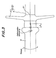
- a detection method according to the invention is performed as follows. At first, as shown in Fig. 3, torques in a circumferential direction rotating in a reverse direction with each other are applied to the securing metal fittings 6 arranged at the both ends of the FRP core 2, after forming an overcoating rubber 7 but before clamping the securing metal fittings 6 to the FRP core 2. It is a matter of course that a torque is applied only to the securing metal fitting 6 if the securing metal fitting 6 is set only to one end of the FRP core 2. Thereby, a parting line 21 along an axial direction of the FRP core 2 generated on a surface of the overcoating 3 during forming the overcoating rubber 7 is deformed, and a deforming amount is measured.
- a deforming amount in a circumferential direction is measured between two points on the parting line 21 with a predetermined distance a along an axial direction of the FRP core 2, one of which is preferably set at a position at which the parting line 21 and the securing metal fitting 6 are contacted, and the detected deforming amount b is defined as the deforming extent in a circumferential direction.
- the reason, that the decision of whether the overcoating rubber is existent or not in the space between the core member and the securing metal fitting can be performed by measuring the deforming amount b of the parting line 21, is as follows. That is to say, as shown in Fig. 4, in the case that the overcoating rubber is not flowed into the space, a power is transmitted to the overcoating 3 through a curing connection portion between the large diameter portion 6a of the securing metal fitting 6 and the overcoating 3 and further to the FRP core 2, when a torque rotating in a circumferential direction is applied to the securing metal fitting 6.
- the securing metal fitting 6 is difficult to move in a circumferential direction even if the torque is applied thereto. Therefore, the overcoating 3 i.e. the parting line 21 is difficult to be deformed.
- an example of the invention and a comparative example were prepared.
- the overcoating rubber 7 is not flowed into the space between the securing metal fitting 6 and the FRP core 2 during forming.
- the overcoating rubber 7 is flowed into the space between the securing metal fitting 6 and the FRP core 2 furring forming.
- the deformation extent was measured when a torque applied to the securing metal fitting 6 is varied. The deformation extent was measured from the deformation amount b between two points where the distance a is set to 20 mm in Fig. 3. The result is shown in Fig. 5. In Fig.
- the example of the invention is largely different from the comparative example on its deformation amount. Therefore, it was confirmed that it is possible to detect whether the overcoating rubber is existent or not in the space between the securing metal fitting and the core member by using a thresh-hold value, if a relation between torque and deformation amount is preliminarily measured for the polymer insulator having the same specification and the thresh-hold value at which the overcoating rubber starts to flow in the space between the securing metal fitting and the core member is determined.
- the present invention is not limited to the embodiments mentioned above, and various modifications can be possible.
- the parting line generated during forming is used as the index provided on a surface of the overcoating, but it is a matter of course that the other means such as a line drawing along an axial direction of the polymer insulator on a surface of the overcoating can be used as the index.
- a torque is applied in a circumferential direction to the securing metal fitting , after forming the overcoating rubber but before fixing to the securing metal fitting to the core member. Therefore, the index provided on a surface of the overcoating, which is preferably the parting line generated on a surface of the overcoating during forming, is deformed, and thus it is possible to detect whether the overcoating rubber is existent or not in the space between the securing metal member and the core member in response to the deforming extent indicated by the index.
- the deforming extent indicated by the index is measured by detecting a deforming amount in a circumferential direction between two points on the parting line with a predetermined distance, one of which is preferably set at a position at which the parting line and the securing metal fitting are contacted, and defining the detected deforming amount between two points as the deforming extent indicated by the index, it is possible to measure the deforming extent correctly.
- a method of detecting an overcoating rubber flowed in a space between a core member and a securing metal fitting of a polymer insulator having the core member, the overcoating arranged around the core member and the securing metal fitting fixed to at least one end of the core member is disclosed.
- the method includes the steps of: applying a torque in a circumferential direction to the securing metal fitting, after forming the overcoating rubber but before fixing the securing metal fitting to the core member; deforming an index provided on a surface of the overcoating; and detecting whether the overcoating rubber is existent or not in the space between the securing metal member and the core member in response to a deforming extent indicated by the index.
Landscapes
- Insulators (AREA)
- Iron Core Of Rotating Electric Machines (AREA)
- Insulating Bodies (AREA)
Applications Claiming Priority (2)
| Application Number | Priority Date | Filing Date | Title |
|---|---|---|---|
| JP394998 | 1998-01-12 | ||
| JP10003949A JPH11203969A (ja) | 1998-01-12 | 1998-01-12 | ポリマー碍子の外被ゴム流入検出方法 |
Publications (2)
| Publication Number | Publication Date |
|---|---|
| EP0929082A2 true EP0929082A2 (de) | 1999-07-14 |
| EP0929082A3 EP0929082A3 (de) | 2000-09-06 |
Family
ID=11571376
Family Applications (1)
| Application Number | Title | Priority Date | Filing Date |
|---|---|---|---|
| EP99100270A Withdrawn EP0929082A3 (de) | 1998-01-12 | 1999-01-08 | Verfahren zur Auffindung des Einfliessens einer Kautschukbeschichtung zwischen Kern und Metallkappe eines Polymerisolators |
Country Status (4)
| Country | Link |
|---|---|
| US (1) | US6189387B1 (de) |
| EP (1) | EP0929082A3 (de) |
| JP (1) | JPH11203969A (de) |
| CA (1) | CA2258452A1 (de) |
Cited By (1)
| Publication number | Priority date | Publication date | Assignee | Title |
|---|---|---|---|---|
| EP1339074A3 (de) * | 2002-02-25 | 2003-12-10 | Ngk Insulators, Ltd. | Verfahren zum Verbinden von einem Kernkörper mit einer Armatur in einem Polymerisolator, und Polymerisolator |
Families Citing this family (4)
| Publication number | Priority date | Publication date | Assignee | Title |
|---|---|---|---|---|
| JP3421353B2 (ja) * | 1997-03-11 | 2003-06-30 | 日本碍子株式会社 | 複合碍子の製造方法及びそれに用いるパッキング部材 |
| RU2392679C1 (ru) * | 2009-06-10 | 2010-06-20 | Закрытое Акционерное Общество "Арматурно-Изоляторный Завод" | Индикатор состояния высоковольтной изоляции |
| CN103903820B (zh) * | 2014-03-14 | 2016-04-20 | 上海昀泰机电科技有限公司 | 用声发射原理检测与控制复合绝缘子压接质量的系统 |
| CN110514525B (zh) * | 2019-08-29 | 2022-04-22 | 江苏神马电力股份有限公司 | 一种内压力对比试验装置 |
Family Cites Families (4)
| Publication number | Priority date | Publication date | Assignee | Title |
|---|---|---|---|---|
| US5059486A (en) * | 1989-06-23 | 1991-10-22 | Rochester Medical Devices, Inc. | Self-healing rubber article and method |
| US5093203A (en) * | 1990-02-06 | 1992-03-03 | Lord Corporation | Polychloroprene-based adhesive system |
| US5162156A (en) * | 1990-09-21 | 1992-11-10 | Lord Corporation | Phenolic resin adhesion promoters and adhesive compositions, and bonding method employing same |
| JP2883880B2 (ja) * | 1994-04-26 | 1999-04-19 | 信越ポリマー株式会社 | コート層付きシリコーンゴム製押釦スイッチ用カバー部材の製造方法 |
-
1998
- 1998-01-12 JP JP10003949A patent/JPH11203969A/ja not_active Withdrawn
- 1998-12-30 US US09/223,291 patent/US6189387B1/en not_active Expired - Fee Related
-
1999
- 1999-01-08 EP EP99100270A patent/EP0929082A3/de not_active Withdrawn
- 1999-01-11 CA CA002258452A patent/CA2258452A1/en not_active Abandoned
Non-Patent Citations (1)
| Title |
|---|
| No relevant documents disclosed * |
Cited By (1)
| Publication number | Priority date | Publication date | Assignee | Title |
|---|---|---|---|---|
| EP1339074A3 (de) * | 2002-02-25 | 2003-12-10 | Ngk Insulators, Ltd. | Verfahren zum Verbinden von einem Kernkörper mit einer Armatur in einem Polymerisolator, und Polymerisolator |
Also Published As
| Publication number | Publication date |
|---|---|
| JPH11203969A (ja) | 1999-07-30 |
| US6189387B1 (en) | 2001-02-20 |
| EP0929082A3 (de) | 2000-09-06 |
| CA2258452A1 (en) | 1999-07-12 |
Similar Documents
| Publication | Publication Date | Title |
|---|---|---|
| US6189387B1 (en) | Method of detecting overcoating rubber flowed in space between core member and securing metal fitting of polymer insulator | |
| CN104483206B (zh) | 一种测量横向各向同性材料剪切性能的装置与方法 | |
| US5598738A (en) | Load apparatus and method for bolt-loaded compact tension test specimen | |
| CN114791413B (zh) | 一种钢芯铝绞线压接缺陷无损检测方法 | |
| EP0674195B2 (de) | Lichtwellenleitersteckeranordnung | |
| US4675965A (en) | Method for manufacturing a pipe part from fibre-reinforced thermosetting synthetic material | |
| JPH036494A (ja) | 核燃料棒等の与圧測定装置及びゲージ | |
| CN113108985B (zh) | 芯丝嵌光栅智能钢绞线拉力值修正计算方法 | |
| KR100246208B1 (ko) | 프리캐스트 콘크리트 부재간 채움재의 직접인장 부착강도 시험방법 및 인장력 전달장치 | |
| JP3421353B2 (ja) | 複合碍子の製造方法及びそれに用いるパッキング部材 | |
| US4126498A (en) | Boots for wire rope terminations | |
| CA1300926C (en) | Rupture testing method for boiler tubes | |
| CN118773933A (zh) | 一种缓粘结预应力钢绞线、制备方法及结构损伤监测方法 | |
| JPH11237325A (ja) | 圧力容器の材料強度の試験方法及び試験治具 | |
| US5691482A (en) | Adhesive shear strength test apparatus | |
| JPH0690196B2 (ja) | ゴムホース劣化測定方法 | |
| JPS6053292B2 (ja) | 海底光ケ−ブルの密封成端構造 | |
| SU934198A1 (ru) | Устройство дл измерени усадочных напр жений в заливочных отверждающихс материалах | |
| CN116297850B (zh) | 热和机械应力作用下环氧嵌件界面失效的声学检测装置 | |
| JPH08313423A (ja) | 電線・ケーブルの劣化診断方法およびそれに用いる治具 | |
| CN119470555A (zh) | 一种基于光纤传感器的管道灌浆密实度的检测装置及方法 | |
| JP2001281077A (ja) | 光ファイバ歪みセンサ | |
| CN121783684A (zh) | 用于薄壁整管疲劳测试的装夹装置及测试方法 | |
| CN211825429U (zh) | 一种硅芯管抗拉性能检测用辅助装置 | |
| JPS6138439A (ja) | 構造体コンクリ−トの強度試験方法 |
Legal Events
| Date | Code | Title | Description |
|---|---|---|---|
| PUAI | Public reference made under article 153(3) epc to a published international application that has entered the european phase |
Free format text: ORIGINAL CODE: 0009012 |
|
| AK | Designated contracting states |
Kind code of ref document: A2 Designated state(s): DE FR IT |
|
| AX | Request for extension of the european patent |
Free format text: AL;LT;LV;MK;RO;SI |
|
| PUAL | Search report despatched |
Free format text: ORIGINAL CODE: 0009013 |
|
| AK | Designated contracting states |
Kind code of ref document: A3 Designated state(s): AT BE CH CY DE DK ES FI FR GB GR IE IT LI LU MC NL PT SE |
|
| AX | Request for extension of the european patent |
Free format text: AL;LT;LV;MK;RO;SI |
|
| 17P | Request for examination filed |
Effective date: 20001017 |
|
| AKX | Designation fees paid |
Free format text: DE FR IT |
|
| GRAP | Despatch of communication of intention to grant a patent |
Free format text: ORIGINAL CODE: EPIDOSNIGR1 |
|
| STAA | Information on the status of an ep patent application or granted ep patent |
Free format text: STATUS: THE APPLICATION IS DEEMED TO BE WITHDRAWN |
|
| 18D | Application deemed to be withdrawn |
Effective date: 20031210 |