EP0929174A2 - Système commutateur amélioré à commande vocale - Google Patents
Système commutateur amélioré à commande vocale Download PDFInfo
- Publication number
- EP0929174A2 EP0929174A2 EP99100441A EP99100441A EP0929174A2 EP 0929174 A2 EP0929174 A2 EP 0929174A2 EP 99100441 A EP99100441 A EP 99100441A EP 99100441 A EP99100441 A EP 99100441A EP 0929174 A2 EP0929174 A2 EP 0929174A2
- Authority
- EP
- European Patent Office
- Prior art keywords
- signal
- voice signal
- attenuation
- voice
- transmitting
- Prior art date
- Legal status (The legal status is an assumption and is not a legal conclusion. Google has not performed a legal analysis and makes no representation as to the accuracy of the status listed.)
- Granted
Links
Images


Classifications
-
- H—ELECTRICITY
- H04—ELECTRIC COMMUNICATION TECHNIQUE
- H04M—TELEPHONIC COMMUNICATION
- H04M9/00—Arrangements for interconnection not involving centralised switching
- H04M9/08—Two-way loud-speaking telephone systems with means for conditioning the signal, e.g. for suppressing echoes for one or both directions of traffic
- H04M9/10—Two-way loud-speaking telephone systems with means for conditioning the signal, e.g. for suppressing echoes for one or both directions of traffic with switching of direction of transmission by voice frequency
Definitions
- This invention relates to a voice switching system for use in a teleconference system, a hand-free telephone system, and the like.
- the publication paper discloses a voice control circuit which prevents a voice system of a teleconference system from an erroneous operation due to a change of a transmitting input level dependent on an amount of echo suppression by an echo canceller.
- a voice control circuit which prevents a voice system of a teleconference system from an erroneous operation due to a change of a transmitting input level dependent on an amount of echo suppression by an echo canceller.
- an input level of a transmission signal is detected by a transmitting input level detector while a reception signal level is detected by a receiving input level detector.
- Still another example of such a conventional voice switching system is exemplified, as a third prior art, in unexamined Japanese Patent Publication No.Hei 4-22249, namely, 22249/1992.
- the publication paper discloses a loudspeaking telephone system which controlls an amount of attenuation of a variable attenuator only by voices through a line in which an echo is cancelled. Namely, in the loudspeaking telephone system, an output of a microphone is attenuated by a primary variable attenuator, and then, an output of the primary variable attenuator is sent to a line. A voice received through the line is attenuated by a secondary variable attenuator to be supplied to a speaker. Thus, an amount of attenuation of the primary and the secondary variable attenuators are controlled by the received voice of which an echo is cancelled in the line.
- a voice switching system comprising: transmitting side attenuation means for attenuating a microphone input voice signal having a first level to produce a transmitting voice signal having a second level; receiving side attenuation means for attenuating a receiving voice signal having a third level to produce a speaker output voice signal having a fourth level; transmitting side control means for comparing the first level of the microphone input voice signal with the fourth level of the speaker output voice signal to obtain a primary difference therebetween, the transmitting side control means controlling, dependent on the primary difference, an amount of attenuation of the microphone input voice signal in the transmitting side attenuation means; and receiving side control means for comparing the second level of the transmitting voice signal with the third level of the receiving voice signal to obtain a secondary difference therebetween, the receiving side control means controlling, dependent on the secondary difference, an amount of attenuation of the receiving voice signal in the receiving side attenuation means.
- the receiving side control means may further comprise: a transmitting side signal delay buffer for providing the transmitting voice signal with a delay time, the delay time corresponding to a time for which the transmitting voice signal returns as the receiving voice signal through a communication line; a transmitting side signal power estimation section for estimating a signal power of the transmitting voice signal outputted from the transmitting side signal delay buffer; a receiving side signal power estimation section for estimating a signal power of the receiving voice signal; a first comparator for comparing a primary estimated signal power of the transmitting voice signal estimated by the transmitting side signal power estimation section with a secondary estimated signal power of the receiving voice signal estimated by the receiving side signal power estimation section to obtain a ratio therebetween; and a first attenuation amount calculation means for calculating an amount of attenuation in the receiving side attenuation means based on the ratio outputted from the first comparator.
- the receiving voice signal inputted to the receiving side signal power estimation section may be silent at the initial time when the transmitting voice signal is inputted to the transmitting side signal delay buffer.
- the transmitting side control means may further comprise: a microphone input power estimation section for estimating a signal power of the microphone input voice signal; a speaker output signal delay buffer for providing the speaker output voice signal with a delay time, the delay time corresponding to a time for which a voice outputted from the speaker becomes the microphone input voice signal by a sound coupling with the microphone; a first speaker output power estimation section for estimating a signal power of the speaker output voice signal outputted from the speaker output signal delay buffer; a second comparator for comparing an estimated signal power of the microphone input voice signal estimated by the microphone input power estimation section with an estimated signal power of the speaker output voice signal estimated by the first speaker output power estimation section to obtain a ratio therebetween; and a second attenuation amount calculation means for calculating an amount of attenuation in the transmitting side attenuation means based on the ratio outputted from the second comparator.
- the microphone input voice signal inputted to the microphone input power estimation section may be silent at the initial time when the speaker output voice signal is inputted to the speaker output signal delay buffer.
- the transmitting side control means may further comprise: a residual echo power estimation section for estimating a signal power of a residual echo signal obtained by the microphone input voice signal passing through an acoustic echo canceller; a second speaker output power estimation section for estimating a signal power of the speaker output voice signal passing through the sound echo canceller; a third comparator for comparing an estimated signal power of the reverberation echo signal estimated by the residual echo power estimation section with an estimated signal power of the speaker output voice signal estimated by the second speaker output power estimation section to obtain a ratio therebetween; and a third attenuation amount calculation means for calculating an amount of attenuation in the transmitting side attenuation means based on the ratio outputted from the third comparator.
- the sound echo canceller may sequentially renew an adaptive filter factor stored in an adaptive filter coefficient buffer by the use of the residual echo signal and a value of an adaptive filter tap input buffer, the residual echo signal being outputted from a subtractor to which the microphone input voice signal is inputted, and wherein sum of products between the adaptive filter coefficient of the adaptive filter coefficient buffer and the value of the adaptive filter tap input buffer is calculated in a sum of products operator, a result of the calculation being subtracted by the subtractor from the microphone input voice signal, thereby the residual echo signal being outputted.
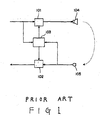
- Fig. 1 is a block diagram for showing a constitution of the conventional voice switch.
- a receiving voice signal received from a side of a communication line is inputted into a receiving side attenuation section 101 and a control section 103.
- a microphone input voice signal gathered by a microphone 105 is inputted into the control section 103 and a transmitting side attenuation section 102.
- the control section 103 controlls an amount of attenuation in the receiving side attenuation section 101 and the transmitting side attenuation section 102.
- the receiving side attenuation section 101 attenuates the receiving voice signal to make a voice be generated from a speaker 104.
- the speaker 104 enlarges the receiving voice all over a room.
- the transmitting side attenuation section 102 attenuates the microphone input voice signal inputted from the microphone 105 to make a transmitting voice signal be outputted to the side of the communication line.
- the control section 103 compares a level of the receiving voice signal with that of the microphone input voice signal inputted from the microphone 105. As a result of the comparison, the control section 103 controlls the receiving side attenuation section 101 and the transmitting side attenuation section 102 so that either the receiving voice signal or the microphone input voice signal having a lower level may further be attenuated.
- a remote end speaker vocalizes, that the receiving voice signal is received, and that no voice signal is inputted into the microphone 105.
- the receiving voice signal is enlarged over the room by the speaker 104 through the receiving side attenuation section 101.
- the voice signal outputted from the speaker 104 turns to the microphone 105 to be again inputted thereinto.
- a gain of sound coupling of the voice signal turning to the microphone 105 from the speaker 104 is smaller than a gain of the control section 103
- it is determined in the control section 103 that an input level of the transmitting side is smaller than an input level of the receiving side.
- the control section 103 controlls the transmitting side attenuation section 102 to make an amount of attenuation larger.
- a near end speaker vocalizes, that a voice signal is inputted into the microphone 105, and that no receiving voice signal is received.
- the microphone input voice signal is transmitted through the transmitting side attenuation section 102.
- the transmitting voice signal thus transmitted returns as the receiving voice signal through a sound coupling between the speaker 104 and the microphone 105 at the remote end side.
- a gain of the sound coupling between the speaker 104 and the microphone 105 is smaller than a gain of the receiving side attenuation section 101
- it is determined in the control section 103 that an input level of the receiving side is smaller than an input level of the transmitting side.
- the control section 103 controlls the receiving side attenuation section 101 to make an amount of attenuation larger.
- an unmatch of timing is inevitably caused to occur between a signal to be attenuated and a reference signal to which the control section 103 refers for determining an amount of attenuation, when a certain delay exists in a communication line, for example, in a case that a processing of voice encoding is inserted therein.
- a certain delay is also generated while a voice outputted from a speaker turns to a microphone to become an input voice of the microphone, for example, in a case that a signal buffer is inserted preceding the speaker output or following the microphone input.
- the unmatch of timing is also caused to occur between the signal to be attenuated and the reference signal.
- An attenuation is inserted within a conversation at an unappropriate timing to deteriorate a quality of the conversation.
- Fig. 2 is a block diagram for showing a constitution of the voice switch according to the first embodiment.
- a receiving voice signal A transmitted from an unillustrated communication line is inputted into a receiving side attenuation section 1 and a receiving side control section 3a.
- a transmitting voice signal D attenuated by a transmitting side attenuation section 2 is also inputted into the receiving side control section 3a.
- the transmitting voice signal D is transmitted to the unillustrated communication line.
- the receiving side control section 3a compares a level of the receiving voice signal A and that of the transmitting voice signal D to detect a difference therebetween. Dependent on the difference thus detected, the receiving side control section 3a controlls an amount of attenuation in the receiving side attenuation section 1.
- the receiving side attenuation section 1 attenuates the receiving voice signal A to produce a speaker output voice signal B.
- the speaker output voice signal B is transmitted to a speaker 4 and a transmitting side control section 3b.
- a voice spreading from the speaker 4 and a voice signal produced by a near end speaker are gathered by a microphone 5 to produce a microphone input voice signal C.
- the microphone input voice signal C is inputted to the transmitting side attenuation section 2 and the transmitting side control section 3b.
- the transmitting side control section 3b compares a level of the microphone input voice signal C and that of the speaker output voice signal B to detect a difference therebetween. Dependent on the difference thus detected, the transmitting side control section 3b controlls an amount of attenuation in the transmitting side attenuation section 2.
- the transmitting side attenuation section 2 produces the transmitting voice signal D. Attenuated by the transmitting side attenuation section 2, the transmitting voice signal D is transmitted to the unillustrated communication line.
- Fig. 3 is a block diagram for showing an internal constitution of the receiving side control section 3a.
- the receiving voice signal A is inputted to a receiving side signal power estimation section 32.
- the transmitting voice signal D is inputted to a transmitting side signal delay buffer 34.
- An output of the transmitting side signal delay buffer 34 is inputted to a transmitting side signal power estimation section 33.
- An output of the receiving side signal power estimation section 32 and an output of the transmitting side signal power estimation section 33 are both inputted to a comparator 31 to be compared with each other.
- An output of the comparator 31 is inputted to an attenuation amount calculation section 30.
- the attenuation amount calculation section 30 outputs a receiving side attenuation amount F.
- the receiving side attenuation amount F is inputted to the receiving side attenuation section 1 illustrated in Fig. 2.
- the receiving side signal power estimation section 32 estimates a voice signal power which is through the unillustrated communication line (lefthand side of Fig. 2) and which is produced by a remote end speaker.
- the receiving side signal power estimation section 32 outputs the estimated voice signal power to the comparator 31.
- the transmitting side signal power estimation section 33 estimates a voice signal power of the transmitting voice signal D which is delayed through the transmitting side signal delay buffer 34.
- the transmitting side signal power estimation section 33 outputs the estimated voice signal power to the comparator 31.
- the comparator 31 compares the estimated voice signal power outputted from the receiving side signal power estimation section 32 with the estimated voice signal power outputted from the transmitting side signal power estimation section 33 to detect a ratio between the both estimated voice signal power. The ratio thus detected is outputted to the attenuation amount calculation section 30.
- the attenuation amount calculation section 30 calculates and produces a receiving side attenuation amount based on the ratio of the both voice signal power inputted from the comparator 31.
- FIG. 4 shows the graph in which the ratio is depicted in a quadrature axis while the amount of attenuation is depicted in an axis of ordinates.
- the amount of attenuation becomes large when the ratio is small.
- the amount of attenuation becomes small when the ratio is large.
- the speaker output voice signal B outputted from the receiving side attenuation section 1 in Fig. 2 is inputted to a speaker output signal delay buffer 44.
- the speaker output signal delay buffer 44 delays the speaker output voice signal B to be outputted to a speaker output power estimation section 43.
- the speaker output power estimation section 43 estimates a power of the speaker output voice signal B delayed by the speaker output signal delay buffer 44. The estimated power is outputted from the speaker output power estimation section 43 to the comparator 41.
- a microphone input voice signal C inputted from the microphone 5 illustrated in Fig. 2 is inputted to the microphone input power estimation section 42.
- the microphone input power estimation section 42 estimates a voice signal power which is corresponding to the speaker 4 and the microphone 5 illustrated in Fig.
- the microphone input power estimation section 42 outputs the estimated voice signal power to the comparator 41.
- the comparator 41 compares the estimated voice signal power of the speaker output voice signal B outputted from the speaker output power estimation section 43 with the estimated voice signal power produced by the near end speaker outputted from the microphone input power estimation section 42 to detect a ratio between the both estimated voice signal power. The ratio thus detected is outputted to the attenuation amount calculation section 40.
- the attenuation amount calculation section 40 calculates and produces a transmitting side attenuation amount based on the ratio of the both voice signal power inputted from the comparator 41.
- the transmitting side attenuation amount is outputted to the transmitting side attenuation section 2 illustrated in Fig. 2.
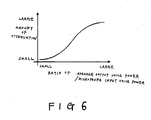
- a relation between the ratio and an output of the attenuation amount calculation section 40 is, for example, shown by a graph in Fig. 6.
- Fig. 6 shows the graph in which the ratio is depicted in a quadrature axis while the amount of attenuation is depicted in an axis of ordinates.
- the amount of attenuation becomes small when the ratio is small.
- the amount of attenuation becomes large when the ratio is large.
- a control of the receiving side attenuation section 1 is hereinunder described.
- the microphone input voice signal C gathered by the microphone 5 and outputted therefrom exists, and that the receiving voice signal A transmitted through the communication line does not exist, namely is silent.
- the microphone input voice signal C is inputted to the transmitting side control section 3b and the transmitting side attenuation section 2.
- the transmitting side control section 3b Since the speaker output voice signal B is not inputted to the transmitting side control section 3b from the receiving side attenuation section 1, the transmitting side control section 3b outputs a small amount of transmitting side attenuation to the transmitting side attenuation section 2. As a result, the transmitting side attenuation section 2 scarcely attenuates any microphone input voice signal C but outputs the transmitting voice signal D to the communication line as a transmission signal.
- the transmitting voice signal D outputted to the communication line is subjected to a sound coupling with an unillustrated speaker and an unillustrated microphone at the remote end side.
- the transmitting voice signal D is returned as the receiving voice signal A through the communication line. In this case, it takes about several hundreds of milliseconds for the transmitting voice signal D to be returned as the receiving voice signal A through the communication line.
- This returned receiving voice signal A is inputted to the receiving side attenuation section 1 and the receiving side control section 3a.
- the receiving voice signal A is inputted to a receiving side signal power estimation section 32.
- the receiving side signal power estimation section 32 estimates a signal power of the receiving voice signal A.
- estimated signal power of the receiving voice signal A is outputted to the comparator 31.
- the transmitting voice signal D outputted from the transmitting side attenuation section 2 in Fig. 2 is inputted to the transmitting side signal delay buffer 34 of the receiving side control section 3a to be delayed therein.
- the delayed transmitting voice signal D is thereafter outputted to the transmitting side signal power estimation section 33.
- the transmitting side signal power estimation section 33 estimates a signal power of the transmitting voice signal D.
- the estimated signal power of the transmitting voice signal D is outputted to the comparator 31.
- the comparator 31 compares a signal power of the receiving voice signal A and that of the transmitting voice signal D.
- the delayed amount of the transmitting voice signal D by the transmitting side signal delay buffer 34 is adjusted to be equal to a delayed amount due to the communication line.
- the delayed amount of the transmitting voice signal D by the transmitting side signal delay buffer 34 is adjusted to be equal to the delayed amount (In this example, several hundreds of milliseconds, as mentioned above) which is generated until the transmitting voice signal is subjected to sound coupling by the speaker and the microphone with a voice produced by a remote end speaker through the communication line and again returned as the receiving voice signal A through the communication line.
- the comparator 31 When a gain of the sound coupling does not exceed "1", the comparator 31 outputs such a signal as increasing an amount of attenuation to the attenuation amount calculation section 30.
- the attenuation amount calculation section 30 outputs a large amount of receiving side attenuation F based on the output by the comparator 31, namely, based on a ratio between both the signal powers of the receiving voice signal A and the transmitting voice signal D.
- the large amount of receiving side attenuation F is outputted to the receiving side attenuation section 1 in Fig. 2. Therefore, the speaker output voice signal B outputted from the receiving side attenuation section 1 is never outputted as the receiving voice signal A which is corresponding to the transmitting voice signal D returned through the communication line. As a result, any voice of the receiving voice signal A is not outputted from the speaker 4.
- the receiving side control section 3a requests a small amount of attenuation to the receiving side attenuation section 1. Consequently, any receiving voice signal A is scarcely attenuated by the receiving side attenuation section 1 and is outputted therefrom to the speaker 4 and the transmitting side control section 3b as the speaker output voice signal B.
- the speaker output voice signal B supplied to the speaker 4 from the receiving side attenuation section 1 drives the speaker 4 to produce a voice.
- An amount of delay by the speaker output signal delay buffer 44 is adjusted to be equal to a delay time which is generated until the speaker output voice signal B is outputted from the speaker 4 as a voice and is gathered by the microphone 5 to be outputted as the microphone input voice signal C with a sound coupling between the speaker and the microphone.
- the speaker output voice signal B is inputted to the speaker output power estimation section 43, as mentioned above. Therein, a signal power of the speaker output voice signal B is estimated. As a result, the estimated signal power of the speaker output voice signal B is inputted to the comparator 41.
- the microphone input voice signal C outputted from the microphone 5 is inputted to the microphone input power estimation section 42. Therein, a signal power of the microphone input voice signal C is estimated. As a result, the estimated signal power of the microphone input voice signal C is inputted to the comparator 41. Accordingly, the comparator 41 compares the estimated signal power of the speaker output voice signal B with the estimated signal power of the microphone input voice signal C.
- the comparator 41 In this comparison by the comparator 41, when a gain of the sound coupling between the speaker 4 and the microphone 5 does not exceed "1", the comparator 41 outputs such a signal as increasing an amount of attenuation to the attenuation amount calculation section 40. Based on the result of the comparison by the comparator 41, the attenuation amount calculation section 40 calculates a transmitting side attenuation amount E to be outputted to the transmitting side attenuation section 2. Accordingly, the transmitting side attenuation section 2 largely attenuates the microphone input voice signal C with reference to the transmitting side attenuation amount E.
- the voice switch according to the first embodiment even if delay is generated in a communication line or delay is generated until a voice outputted from the speaker 4 turns to the microphone 5 to become a microphone input, the receiving side control section 3a and the transmitting side control section 3b are capable of adequate switching operations, respectively. Accordingly, a quality of conversation is so improved.
- Fig. 7 is a block diagram for showing a constitution of the voice switch according to the second embodiment.
- the voice switch according to the second embodiment has a structure similar to that of the first embodiment. Similar portions are designated by like reference numerals.
- a reference numeral 3c different from that of Fig. 2 is attached to a transmitting side control section in Fig. 7.
- an acoustic cho canceller 6 is further provided in addition to the constitution of Fig. 2.
- a control of the transmitting side control section 3c is related to the acoustic echo canceller 6.
- the speaker output voice signal B outputted from the receiving side attenuation section 1 is not only outputted to the speaker 4 but also inputted to the transmitting side control section 3c through the sound echo canceller 6.
- the microphone input voice signal C outputted from the microphone 5 is also inputted to the acoustic echo canceller 6 to be outputted therefrom as a residual echo signal G.
- the residual echo signal G is supplied to both the transmitting side attenuation section 2 and the transmitting side control section 3c.
- Other portions are similar to those of the first embodiment illustrated in Fig. 2.
- Fig. 8 is a block diagram for showing internal constitutions of the acoustic echo canceller 6 and the transmitting side control section 3c.
- the transmitting side control section 3c comprises an attenuation amount calculation section 50, a comparator 51, a residual echo power estimation section 52, and a speaker output power estimation section 53.
- the sound echo canceller 6 comprises an adaptive filter 61 and a subtractor 65.
- the adaptive filter 61 comprises an adaptive filter tap input buffer 62, sum of products operator 63 and an adaptive filter coefficient buffer 64.
- the above-mentioned microphone input voice signal C outputted from the microphone 5 is inputted to the subtractor 65. Further, an output of the sum of products operator 63 is also inputted to the subtractor 65.
- the residual echo signal G is outputted not only to the residual echo power estimation section 52 in the transmitting side control section 3c but also to the adaptive filter 61 in the acoustic echo canceller 6.
- the speaker output voice signal B outputted from the transmitting side attenuation section 1 illustrated in Fig. 7 is inputted to the adaptive filter tap input buffer 62.
- An output of the adaptive filter tap input buffer 62 is inputted to the speaker output power estimation section 53.
- the adaptive filter 61 sequentially renews an adaptive filter coefficient stored in the adaptive filter coefficient buffer 64 by the use of the residual echo signal G and a value of the adaptive filter tap input buffer 62.
- the sum of products between the adaptive filter coeffieient of the adaptive filter factor buffer 64 and the value of the adaptive filter tap input buffer 62 is calculated in the sum of products operator 63.
- a result of the calculation is outputted to the subtractor 65.
- the subtractor 65 subtracts the result of the calculation in the sum of products operator 63 from the microphone input voice signal C to produce the residual echo signal G.
- the speaker output power estimation section 53 estimates a signal power of the speaker output voice signal B.
- the estimated signal power of the speaker output voice signal B is outputted to the comparator 51.
- the residual echo signal G is inputted to the residual echo power estimation section 52 in the transmitting side control section 3c.
- the comparator 51 compares a signal power of the speaker output voice signal B with a signal power of a voice of a near end speaker outputted from the residual echo power estimation section 52 to detect a ratio therebetween. The ratio is outputted from the comparator 51 to the attenuation amount calculation section 50.
- the attenuation amount calculation section 50 calculate and decide an amount of transmitting side attenuation based on the ratio inputted from the comparator 51.
- the amount of transmitting side attenuation is outputted to the transmitting side attenuation section 2 in Fig. 7.
- the adaptive filter tap input buffer 62 in Fig. 8 functions similarly to the speaker output signal delay buffer 44 in the first embodiment. Accordingly, the speaker output signal delay buffer 44 in the first embodiment can be replaced with the adaptive filter tap input buffer 62.
- the voice switch of the present invention is used together with the acoustic echo canceller 6, the speaker output signal delay buffer required for delaying the speaker output voice signal can be omitted. Further, with reference to a result of study of factors in the adaptive filter 61, an amount of delay of the speaker output voice signal B can be controlled.
- a level of the speaker output voice signal and a level of the microphone input voice signal are compared with each other in the transmitting side control section. Dependent on a difference between the both levels, the level of the microphone input voice signal is attenuated to obtain the transmitting voice signal. Further, a level of the receiving voice signal and a level of the transmitting voice signal are compared with each other in the receiving side control section. Dependent on a difference between the both levels, the level of the receiving voice signal is attenuated to obtain the speaker output voice signal.
Landscapes
- Engineering & Computer Science (AREA)
- Signal Processing (AREA)
- Cable Transmission Systems, Equalization Of Radio And Reduction Of Echo (AREA)
- Interconnected Communication Systems, Intercoms, And Interphones (AREA)
- Telephone Function (AREA)
Applications Claiming Priority (2)
| Application Number | Priority Date | Filing Date | Title |
|---|---|---|---|
| JP1512298 | 1998-01-09 | ||
| JP01512298A JP3220979B2 (ja) | 1998-01-09 | 1998-01-09 | 音声スイッチ |
Publications (3)
| Publication Number | Publication Date |
|---|---|
| EP0929174A2 true EP0929174A2 (fr) | 1999-07-14 |
| EP0929174A3 EP0929174A3 (fr) | 2005-03-16 |
| EP0929174B1 EP0929174B1 (fr) | 2007-10-24 |
Family
ID=11880027
Family Applications (1)
| Application Number | Title | Priority Date | Filing Date |
|---|---|---|---|
| EP99100441A Expired - Lifetime EP0929174B1 (fr) | 1998-01-09 | 1999-01-11 | Système commutateur amélioré à commande vocale |
Country Status (5)
| Country | Link |
|---|---|
| EP (1) | EP0929174B1 (fr) |
| JP (1) | JP3220979B2 (fr) |
| KR (1) | KR19990067811A (fr) |
| AU (1) | AU755658B2 (fr) |
| DE (1) | DE69937380T2 (fr) |
Cited By (1)
| Publication number | Priority date | Publication date | Assignee | Title |
|---|---|---|---|---|
| CN103202006A (zh) * | 2011-02-17 | 2013-07-10 | 夏普株式会社 | 电子设备、电子设备的控制方法、控制程序以及记录介质 |
Families Citing this family (5)
| Publication number | Priority date | Publication date | Assignee | Title |
|---|---|---|---|---|
| JP3553008B2 (ja) * | 2000-09-26 | 2004-08-11 | 岩崎通信機株式会社 | エコー低減方法および電話装置 |
| JP4161628B2 (ja) | 2002-07-19 | 2008-10-08 | 日本電気株式会社 | エコー抑圧方法及び装置 |
| US7894598B2 (en) * | 2004-12-14 | 2011-02-22 | Nuance Communications, Inc. | System for limiting receive audio |
| DE112007003625T5 (de) | 2007-08-24 | 2010-07-15 | Fujitsu Ltd., Kawasaki | Echounterdrückungsvorrichtung, echounterdrückungssystem, Echounterdrückungsverfahren und Computerprogramm |
| JP4900185B2 (ja) * | 2007-10-16 | 2012-03-21 | パナソニック電工株式会社 | 拡声通話装置 |
Family Cites Families (13)
| Publication number | Priority date | Publication date | Assignee | Title |
|---|---|---|---|---|
| JPS6016773B2 (ja) * | 1976-12-14 | 1985-04-27 | 日本電気株式会社 | 双方向通話検出器 |
| US4724540A (en) * | 1986-09-02 | 1988-02-09 | Motorola, Inc. | Speakerphone with fast idle mode |
| JP2751244B2 (ja) * | 1988-02-18 | 1998-05-18 | 日本電気株式会社 | ハンズフリー回路及びハンズフリー制御方式 |
| JP2634946B2 (ja) * | 1990-11-19 | 1997-07-30 | 日本電気株式会社 | ハンズフリー補助回路 |
| JP3076072B2 (ja) * | 1991-02-19 | 2000-08-14 | 日本電気株式会社 | 拡声電話装置および該装置に用いる騒音抑圧回路 |
| JPH04323938A (ja) * | 1991-04-23 | 1992-11-13 | Toshiba Corp | ハンズフリー回路 |
| CA2052351C (fr) * | 1991-09-27 | 2000-05-23 | Gordon J. Reesor | Circuit de telephone a mains libres |
| JPH0678046A (ja) * | 1992-08-25 | 1994-03-18 | Fujitsu Ltd | ハンズフリー・システムで用いられる音声スイッチ |
| US5668871A (en) * | 1994-04-29 | 1997-09-16 | Motorola, Inc. | Audio signal processor and method therefor for substantially reducing audio feedback in a cummunication unit |
| JPH08204619A (ja) * | 1995-01-26 | 1996-08-09 | Nec Corp | エコーサプレッサ |
| JPH08335976A (ja) * | 1995-06-06 | 1996-12-17 | Kobe Steel Ltd | 拡声通話装置 |
| DE19620031C1 (de) * | 1996-05-17 | 1997-05-28 | Siemens Ag | Verfahren zur automatischen Justierung einer Schalteinrichtung zum automatischen Umschalten zwischen einer Empfangsbetriebsart und einer Sendebetriebsart bei einer Freisprecheinrichtung eines Kommunikationsendgerätes |
| US5857019A (en) * | 1996-06-11 | 1999-01-05 | Siemens Business Communication Systems, Inc. | Apparatus and method for providing a telephone user with control of the threshold volume at which the user's voice will take control of a half-duplex speakerphone conversation |
-
1998
- 1998-01-09 JP JP01512298A patent/JP3220979B2/ja not_active Expired - Fee Related
-
1999
- 1999-01-08 AU AU10081/99A patent/AU755658B2/en not_active Ceased
- 1999-01-09 KR KR1019990000328A patent/KR19990067811A/ko not_active Ceased
- 1999-01-11 DE DE69937380T patent/DE69937380T2/de not_active Expired - Lifetime
- 1999-01-11 EP EP99100441A patent/EP0929174B1/fr not_active Expired - Lifetime
Cited By (3)
| Publication number | Priority date | Publication date | Assignee | Title |
|---|---|---|---|---|
| CN103202006A (zh) * | 2011-02-17 | 2013-07-10 | 夏普株式会社 | 电子设备、电子设备的控制方法、控制程序以及记录介质 |
| CN103202006B (zh) * | 2011-02-17 | 2016-02-17 | 夏普株式会社 | 电子设备、以及电子设备的控制方法 |
| US9397628B2 (en) | 2011-02-17 | 2016-07-19 | Sharp Kabushiki Kaisha | Electronic device, controlling method and controlling program for electronic device, and recording medium |
Also Published As
| Publication number | Publication date |
|---|---|
| JPH11205199A (ja) | 1999-07-30 |
| AU755658B2 (en) | 2002-12-19 |
| DE69937380T2 (de) | 2008-02-14 |
| JP3220979B2 (ja) | 2001-10-22 |
| AU1008199A (en) | 1999-07-29 |
| DE69937380D1 (de) | 2007-12-06 |
| EP0929174B1 (fr) | 2007-10-24 |
| EP0929174A3 (fr) | 2005-03-16 |
| KR19990067811A (ko) | 1999-08-25 |
Similar Documents
| Publication | Publication Date | Title |
|---|---|---|
| US7203308B2 (en) | Echo canceller ensuring further reduction in residual echo | |
| CA2414972C (fr) | Methode de commande de gain en vue de l'attenuation ou de la suppression d'echo acoustique | |
| JP2538176B2 (ja) | エコ―制御装置 | |
| US6181794B1 (en) | Echo canceler and method thereof | |
| US5764753A (en) | Half-duplex controller | |
| CN101346897B (zh) | 回声消除器 | |
| US6532289B1 (en) | Method and device for echo suppression | |
| US6516050B1 (en) | Double-talk detecting apparatus, echo canceller using the double-talk detecting apparatus and echo suppressor using the double-talk detecting apparatus | |
| JPH09172396A (ja) | 音響結合の影響を除去するためのシステムおよび方法 | |
| JPH10341190A (ja) | エコー消去システム及び方法、並びに移動通信装置 | |
| US6185299B1 (en) | Adaptive echo cancellation device in a voice communication system | |
| JP3385221B2 (ja) | エコーキャンセラ | |
| EP0929174B1 (fr) | Système commutateur amélioré à commande vocale | |
| US6608897B1 (en) | Double-talk insensitive NLMS algorithm | |
| EP1786191A1 (fr) | Annuleur d'écho acoustique | |
| US6901143B1 (en) | Voice switching system capable of improving a quality of conversation | |
| GB2312600A (en) | Adaptive echo cancellation | |
| TWI399968B (zh) | 揚聲電話裝置 | |
| JP2003051879A (ja) | 通話装置 | |
| JPH06503699A (ja) | エコーキャンセラーにおける非線形信号処理方法 | |
| US20100002866A1 (en) | Voice communication apparatus | |
| JP3941581B2 (ja) | 拡声通話装置 | |
| JPH07226697A (ja) | 反響消去装置、反響消去方法及び反響消去装置を有する送受話器 | |
| JPH0766756A (ja) | 音響エコーキャンセラ | |
| JPH07226700A (ja) | 反響消去装置 |
Legal Events
| Date | Code | Title | Description |
|---|---|---|---|
| PUAI | Public reference made under article 153(3) epc to a published international application that has entered the european phase |
Free format text: ORIGINAL CODE: 0009012 |
|
| AK | Designated contracting states |
Kind code of ref document: A2 Designated state(s): AT BE CH CY DE DK ES FI FR GB GR IE IT LI LU MC NL PT SE |
|
| AX | Request for extension of the european patent |
Free format text: AL;LT;LV;MK;RO;SI |
|
| PUAL | Search report despatched |
Free format text: ORIGINAL CODE: 0009013 |
|
| AK | Designated contracting states |
Kind code of ref document: A3 Designated state(s): AT BE CH CY DE DK ES FI FR GB GR IE IT LI LU MC NL PT SE |
|
| AX | Request for extension of the european patent |
Extension state: AL LT LV MK RO SI |
|
| 17P | Request for examination filed |
Effective date: 20050214 |
|
| AKX | Designation fees paid |
Designated state(s): DE FR GB IT SE |
|
| GRAP | Despatch of communication of intention to grant a patent |
Free format text: ORIGINAL CODE: EPIDOSNIGR1 |
|
| GRAS | Grant fee paid |
Free format text: ORIGINAL CODE: EPIDOSNIGR3 |
|
| GRAA | (expected) grant |
Free format text: ORIGINAL CODE: 0009210 |
|
| RIN1 | Information on inventor provided before grant (corrected) |
Inventor name: ONO, YOSHIHIRO C/O |
|
| AK | Designated contracting states |
Kind code of ref document: B1 Designated state(s): DE FR GB IT SE |
|
| REG | Reference to a national code |
Ref country code: GB Ref legal event code: FG4D |
|
| REF | Corresponds to: |
Ref document number: 69937380 Country of ref document: DE Date of ref document: 20071206 Kind code of ref document: P |
|
| PG25 | Lapsed in a contracting state [announced via postgrant information from national office to epo] |
Ref country code: SE Free format text: LAPSE BECAUSE OF FAILURE TO SUBMIT A TRANSLATION OF THE DESCRIPTION OR TO PAY THE FEE WITHIN THE PRESCRIBED TIME-LIMIT Effective date: 20080124 |
|
| ET | Fr: translation filed | ||
| PLBE | No opposition filed within time limit |
Free format text: ORIGINAL CODE: 0009261 |
|
| 26N | No opposition filed |
Effective date: 20080725 |
|
| REG | Reference to a national code |
Ref country code: GB Ref legal event code: 732E Free format text: REGISTERED BETWEEN 20141023 AND 20141029 |
|
| REG | Reference to a national code |
Ref country code: FR Ref legal event code: TP Owner name: LENOVO INNOVATIONS LIMITED (HONG KONG), HK Effective date: 20141119 |
|
| REG | Reference to a national code |
Ref country code: FR Ref legal event code: PLFP Year of fee payment: 17 |
|
| PGFP | Annual fee paid to national office [announced via postgrant information from national office to epo] |
Ref country code: IT Payment date: 20150114 Year of fee payment: 17 Ref country code: DE Payment date: 20150106 Year of fee payment: 17 |
|
| PGFP | Annual fee paid to national office [announced via postgrant information from national office to epo] |
Ref country code: GB Payment date: 20150107 Year of fee payment: 17 Ref country code: FR Payment date: 20150108 Year of fee payment: 17 |
|
| REG | Reference to a national code |
Ref country code: DE Ref legal event code: R119 Ref document number: 69937380 Country of ref document: DE |
|
| GBPC | Gb: european patent ceased through non-payment of renewal fee |
Effective date: 20160111 |
|
| REG | Reference to a national code |
Ref country code: FR Ref legal event code: ST Effective date: 20160930 |
|
| PG25 | Lapsed in a contracting state [announced via postgrant information from national office to epo] |
Ref country code: DE Free format text: LAPSE BECAUSE OF NON-PAYMENT OF DUE FEES Effective date: 20160802 Ref country code: GB Free format text: LAPSE BECAUSE OF NON-PAYMENT OF DUE FEES Effective date: 20160111 |
|
| PG25 | Lapsed in a contracting state [announced via postgrant information from national office to epo] |
Ref country code: FR Free format text: LAPSE BECAUSE OF NON-PAYMENT OF DUE FEES Effective date: 20160201 |
|
| PG25 | Lapsed in a contracting state [announced via postgrant information from national office to epo] |
Ref country code: IT Free format text: LAPSE BECAUSE OF NON-PAYMENT OF DUE FEES Effective date: 20160111 |