EP0929188A2 - Imprimante en couleur - Google Patents
Imprimante en couleur Download PDFInfo
- Publication number
- EP0929188A2 EP0929188A2 EP99300028A EP99300028A EP0929188A2 EP 0929188 A2 EP0929188 A2 EP 0929188A2 EP 99300028 A EP99300028 A EP 99300028A EP 99300028 A EP99300028 A EP 99300028A EP 0929188 A2 EP0929188 A2 EP 0929188A2
- Authority
- EP
- European Patent Office
- Prior art keywords
- latent image
- image
- facet
- scan line
- image area
- Prior art date
- Legal status (The legal status is an assumption and is not a legal conclusion. Google has not performed a legal analysis and makes no representation as to the accuracy of the status listed.)
- Granted
Links
- 108091008695 photoreceptors Proteins 0.000 claims description 37
- 239000000758 substrate Substances 0.000 claims description 20
- 238000007639 printing Methods 0.000 claims description 16
- 238000000034 method Methods 0.000 claims description 13
- 238000012546 transfer Methods 0.000 claims description 5
- 238000010408 sweeping Methods 0.000 claims description 3
- 230000004044 response Effects 0.000 claims description 2
- 230000001939 inductive effect Effects 0.000 claims 6
- 238000000151 deposition Methods 0.000 claims 2
- 238000003384 imaging method Methods 0.000 abstract description 3
- 230000000979 retarding effect Effects 0.000 abstract description 2
- 238000000926 separation method Methods 0.000 abstract description 2
- 238000011161 development Methods 0.000 description 12
- 239000002131 composite material Substances 0.000 description 10
- 230000008569 process Effects 0.000 description 6
- 230000009286 beneficial effect Effects 0.000 description 3
- 230000008878 coupling Effects 0.000 description 3
- 238000010168 coupling process Methods 0.000 description 3
- 238000005859 coupling reaction Methods 0.000 description 3
- 239000002245 particle Substances 0.000 description 3
- 230000008901 benefit Effects 0.000 description 2
- 150000002500 ions Chemical class 0.000 description 2
- 238000002360 preparation method Methods 0.000 description 2
- 230000015572 biosynthetic process Effects 0.000 description 1
- 238000004140 cleaning Methods 0.000 description 1
- 239000003086 colorant Substances 0.000 description 1
- 230000008602 contraction Effects 0.000 description 1
- 230000007547 defect Effects 0.000 description 1
- 230000000694 effects Effects 0.000 description 1
- 238000005516 engineering process Methods 0.000 description 1
- 238000004519 manufacturing process Methods 0.000 description 1
- 239000000463 material Substances 0.000 description 1
- 239000011159 matrix material Substances 0.000 description 1
- 238000012545 processing Methods 0.000 description 1
- 230000001105 regulatory effect Effects 0.000 description 1
- 230000001360 synchronised effect Effects 0.000 description 1
- 238000012360 testing method Methods 0.000 description 1
Images

Classifications
-
- H—ELECTRICITY
- H04—ELECTRIC COMMUNICATION TECHNIQUE
- H04N—PICTORIAL COMMUNICATION, e.g. TELEVISION
- H04N1/00—Scanning, transmission or reproduction of documents or the like, e.g. facsimile transmission; Details thereof
- H04N1/46—Colour picture communication systems
- H04N1/50—Picture reproducers
- H04N1/506—Reproducing the colour component signals picture-sequentially, e.g. with reproducing heads spaced apart from one another in the subscanning direction
- H04N1/508—Reproducing the colour component signals picture-sequentially, e.g. with reproducing heads spaced apart from one another in the subscanning direction using the same reproducing head for two or more colour components
Definitions
- Electrophotographic marking is a well known and commonly used method of copying or printing documents. Electrophotographic marking is performed by exposing a light image representation of a desired document onto a substantially uniformly charged photoreceptor. In response to that light image the photoreceptor discharges, creating an electrostatic latent image of the desired document on the photoreceptor's surface. Toner particles are then deposited onto that latent image, forming a toner image. That toner image is then transferred from the photoreceptor onto a substrate such as a sheet of paper. The transferred toner image is then fused to the substrate, usually using heat and/or pressure, thereby creating a copy of the desired image. The surface of the photoreceptor is then cleaned of residual developing material and recharged in preparation for the production of another image.
- Electrophotographic marking can also produce color images by repeating the above process once for each color of toner that is used to make the composite color image.
- the various color toner can then be transferred onto a substrate in a superimposed registration so that a desired composite color image results. That composite color image can then be fused to make a permanent image.
- a ROS is usually comprised of a laser light source (or sources) and a rotating polygon having a plurality of mirrored facets.
- the light source radiates a laser beam onto the polygon facets.
- the facets reflect the light onto the photoreceptor where a light spot is produced.
- scan lines As the polygon rotates the spot traces lines, referred to as scan lines, on the photoreceptor. Since the photoreceptor itself usually moves, the surface of the photoreceptor is raster scanned by the spot.
- the laser beam is modulated to produce a latent image on the photoreceptor. Then, depending upon the printer's configuration, the laser beam can be modulated to produce a latent image for each color of toner to be developed.
- This invention relates to a technique of reducing or eliminating color banding in a composite color image that is derived from a plurality of superimposed raster scanned color images.
- the first scan line of each raster scanned color image is produced using the same facet.
- corresponding scan lines in all of the images are produced using the same facet.
- the scan line offsets that are required to properly register each raster scanned color image are produced by rotating a cylinder mirror.
- FIG 1 illustrates an electrophotographic printing machine 8 that is in accord with the principles of the present invention. It is to be understood that the present invention can be used in many machines and systems other than that which is specifically illustrated. However, understanding how the present invention is used in the printing machine 8 will assist the understanding of the invention.
- the printing machine 8 includes an Active Matrix (AMAT) photoreceptor belt 10 which travels in the direction indicated by the arrow 12. Belt travel is brought about by mounting the photoreceptor belt about a driven roller 14 and tension rollers 16 and 18. The driven roller 14 is driven by a motor 20.
- AMAT Active Matrix
- the image area is that part of the photoreceptor belt which is to receive the various toner layers which, after being transferred and fused to a substrate, produce the final color image. While the photoreceptor belt may have numerous image areas, since each image area is processed in the same way a description of the processing of one image area suffices to fully explain the operation of the printing machine.
- the imaging process begins with the image area passing a "precharge" erase lamp 21 that illuminates the image area so as to cause any residual charge which might exist on the image area to be discharged.
- a "precharge” erase lamp 21 that illuminates the image area so as to cause any residual charge which might exist on the image area to be discharged.
- Such erase lamps are common in high quality systems and their use for initial erasure is well known.
- the image area passes a charging station comprised of a DC corotron 22 and an AC scorotron 23.
- the DC corotron charges the image area in preparation for exposure to create a latent image for black toner.
- the DC corotron might charge the image area to a substantially uniform potential of about -500 volts. It should be understood that the actual charge placed on the photoreceptor will depend upon many variables, such as the black toner mass that is to be developed and the settings of the black development station (see below).
- the AC scorotron 23 is used in subsequent passes of the image area through the printing machine 8.
- the image area After passing the charging station the image area advances to an exposure station 24.
- the charged image area is exposed to a modulated laser beam 26 from a raster output scanner 27 that raster scans the image area such that an electrostatic latent representation of a black image is produced.
- illuminated sections of the image area might be discharged by the beam 26 to about -100 volts.
- the image area has a voltage profile comprised of relatively high voltage areas of about -500 volts and of relatively low voltage areas of about -100 volts.
- the printing machine 8 beneficially departs from prior art REaD printing machines in the configuration of the raster output scanner.
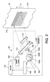
- Figure 2 illustrates the raster scanning of the photoreceptor 12 in more detail.
- the printing machine 8 includes a polygon 100 having a plurality of facets, the facets 102A, 102B, and 102C, and five other facets that are not specifically enumerated.
- a laser 104 generates the laser beam 26 which illuminates a facet. Since the polygon 100 rotates in the direction 106 the laser beam 26 sweeps through an angle 108.
- the sweeping laser beam 26 is reflected from a first mirror 110, then from a rotating cylinder mirror 112, and finally the sweeping beam sweeps a scan line on the photoreceptor 10.
- the polygon 100, laser 104, first mirror 110, and cylinder mirror 112 are all located within the raster output scanner 27.
- the polygon facets are not perfect, that is, facet 102A is slightly different than facet 102B, which is different than facet 102C, and so on. These differences cause each scan line to have a different amount of nonuniformity.
- a start of scan detector (not shown) and the cylindrical mirror 112 compensate for some scan line nonuniformities.
- a start of scan detector can assist synchronization such that the modulation of each scan line starts with the spot at the same distance from an edge 116 and the cylindrical mirror compensates for scan line wobble.
- neither the start of scan detector nor the cylindrical mirror correct for scan line nonlinearity. That is, as the scan line sweeps toward the edge 118, facet imperfections cause the position of the spot produced by the laser beam 26 at a given time after the start of scan to vary from scan line to scan line. This is important in what follows.
- the exposed image area with the black latent image passes a black development station 32 that advances black toner 34 onto the image area so as to develop a black latent image.
- the black development station 32 could be a magnetic brush developer, a scavengeless developer may be somewhat better.
- One benefit of scavengeless development is that it does not disturb previously deposited toner layers. Biasing is such as to effect discharged area development (DAD) of the lower (less negative) of the two voltage levels on the photoreceptor.
- DAD discharged area development
- the charged black toner 34 adheres to the exposed areas of the image area, thereby causing the voltage of the illuminated parts of the image area to be about -200 volts.
- the non-illuminated parts of the image area remain at about -500 volts.
- the image area After passing the black development station 32 the image area advances to the charging station.
- the DC corotron 22 and the AC scorotron 23 then recharge the image area and its black toner layer using a technique known as split recharging.
- the DC corotron 22 overcharges the image are to a voltage level greater than that desired when the image area is recharged, while the AC scorotron reduces that voltage level to that which is desired.
- Split recharging serves to substantially eliminate voltage differences between toned areas and untoned areas and to reduce the level of residual charge remaining on the previously toned areas. This benefits subsequent development by different toners.
- the recharged image area with its black toner layer then advances to the exposure station. There the laser beam 26 exposes the image area to produce an electrostatic latent representation of a yellow image.
- the modulation of the laser beam is controlled such that the first scan line of the yellow image is scanned using the same facet as the first scan line of the black image.
- facet synchronization is achieved using a facet detector 120 that detects when a predetermined facet is in position to be illuminated by the laser 104.
- the facet detector applies a synchronizing signal to a controller 121 that, in turn outputs signals to a modulator 122 that causes the modulator to synchronize laser beam modulation with the facets. Since the yellow image has the same number of scan lines as the black image, beginning the yellow image with the same facet as the black image means that corresponding scan lines in the two images are produced using the same facet.
- a facet detector is not absolutely required.
- the polygon might be rotated using either a stepper motor or a synchronized AC motor.
- tracking the signals to the motor such as by counting pulses or by counting input cycles, and by taking into consideration the number of facets on the polygon, it is possible to know when a particular facet is in position to be illuminated by the laser 104.
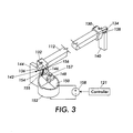
- end caps 130 and 132 are placed on the cylindrical mirror 112.
- the end cap 130 has a knife edge 134 while the end cap 132 has a knife edge 136.
- the knife edge 134 fits into a notch 138 of a stand 140, and the knife edge 136 fits into a notch 142 of a stand 144.
- the cylinder mirror thus pivots about the notches 138 and 142.
- the end cap 132 includes a lever arm 146 that terminates in a threaded coupling 148. Below the threaded coupling is a piezoelectric element 150 in a support 152. A spring 154 stretched between a stand pin 155 and a lever pin 156 biases the lever arm toward the piezoelectric element 150. A screw 157 passing through a threaded coupling contacts the piezoelectric element. By adjusting the screw the pivot of the cylinder mirror can be adjusted.
- a controlled voltage source 158 is applied to the piezoelectric element.
- a bias applied to a piezoelectric element causes the piezoelectric element to expand or contract, depending upon the polarity.
- the controlled voltage source causes the cylindrical mirror 112 to pivot.
- the components 130-158 comprise a rotation control system 160 shown in Figure 2.
- the axis of rotation of the cylinder mirror 112 is beneficially carefully chosen and controlled. It should run parallel to the axis of formation of the cylinder mirror itself. The axis of rotation of the cylinder mirror should also run tangential to the surface of the cylinder mirror.
- the controller 121 causes the controlled voltage source 158 to apply a voltage to the piezoelectric element 150 such that the cylinder mirror pivots the proper amount such that the first scan lines of all of the images are registered.
- the controller 121 determines the required expansion or contraction of the piezoelectric element such that when the first line of the yellow latent image is imaged using the same facet as the first line of the black image that those latent images are registered.
- the now re-exposed image area advances to a yellow development station 46 that deposits yellow toner 48 onto the image area.
- the image area advances once again to the charging station.
- the DC corotron 22 and the AC scorotron 23 again recharge the image area using split recharging.
- the recharged image area with its black and yellow toners then advances once again to the exposure station.
- the exposure station then exposes the image area to produce an electrostatic latent representation of a magenta image.
- the first scan line of the magenta image is produced using the same facet as that which produced the black and yellow images. If the correct polygon facet is not being illuminated by the laser when the magenta image area is registered with the black and yellow toner layers, the cylindrical mirror is rotated by the piezoelectric element as described above so that the images are registered.
- magenta exposure station After passing the magenta exposure station the now re-exposed image area advances to a magenta development station 56 that deposits magenta toner 58 onto the image area. After passing the magenta development station the image area advances yet again to the charging station where the DC corotron and the AC scorotron split recharge the image area.
- the now recharged image area with its black, yellow, and magenta toner layers then advances once again to the exposure station. That station exposes the image area to produce an electrostatic latent representation of a cyan image. The exposure station then exposes the image area to produce an electrostatic latent representation of a cyan image. Once again, the first scan line of the cyan image is produced using the same facet as that which produced the black, yellow, and magenta images. If the correct polygon facet is not being illuminated by the laser when the cyan image area is registered with the other toner layers, the cylindrical mirror is rotated by the piezoelectric element as described above such that the images are registered.
- the now re-exposed image area advances past a cyan development station 66 that deposits cyan toner 68 onto the image area.
- cyan toner 68 deposits cyan toner 68 onto the image area.
- four colors of toner are on the image area, resulting in a composite color image.
- the composite color toner image is comprised of individual toner particles which have charge potentials which vary widely. Directly transferring such a composite toner image onto a substrate would result in a degraded final image. Therefore it is beneficial to prepare the composite color toner image for transfer.
- a pretransfer erase lamp 70 discharges the image area to produce a relatively low charge level on the image area.
- the image area then passes a pretransfer DC scorotron 80 which performs a pre-transfer charging function.
- the image area continues to advance in the direction 12 past the driven roller 14.
- a substrate 82 is then placed over the image area using a sheet feeder (which is not shown).
- a detack corotron 86 that corotron neutralizes some of the charge on the substrate to assist separation of the substrate from the photoreceptor 10.
- the substrate is then directed into a fuser 90 where a heated fuser roller 92 and a pressure roller 94 create a nip through which the substrate 82 passes.
- the combination of pressure and heat at the nip causes the composite color toner image to fuse into the substrate.
- a chute guides the substrate to a catch tray, also not shown, for removal by an operator.
- the image area continues its travel and passes a preclean erase lamp 98. That lamp neutralizes most of the charge remaining on the photoreceptor belt. After passing the preclean erase lamp the residual toner and/or debris on the photoreceptor is removed at a cleaning station 99. The image area then passes once again to the precharge erase lamp 21 and the start of another printing cycle.
- controller 121 Using well known technology the various machine functions described above are generally managed and regulated by the controller 121.
Landscapes
- Engineering & Computer Science (AREA)
- Multimedia (AREA)
- Signal Processing (AREA)
- Color Electrophotography (AREA)
- Facsimile Scanning Arrangements (AREA)
- Exposure Or Original Feeding In Electrophotography (AREA)
- Laser Beam Printer (AREA)
- Mechanical Optical Scanning Systems (AREA)
- Color, Gradation (AREA)
Applications Claiming Priority (2)
| Application Number | Priority Date | Filing Date | Title |
|---|---|---|---|
| US4455 | 1998-01-08 | ||
| US09/004,455 US6055005A (en) | 1998-01-08 | 1998-01-08 | Color printer with jitter signature matching |
Publications (3)
| Publication Number | Publication Date |
|---|---|
| EP0929188A2 true EP0929188A2 (fr) | 1999-07-14 |
| EP0929188A3 EP0929188A3 (fr) | 2000-11-29 |
| EP0929188B1 EP0929188B1 (fr) | 2006-04-19 |
Family
ID=21710896
Family Applications (1)
| Application Number | Title | Priority Date | Filing Date |
|---|---|---|---|
| EP99300028A Expired - Lifetime EP0929188B1 (fr) | 1998-01-08 | 1999-01-04 | Imprimante en couleur |
Country Status (4)
| Country | Link |
|---|---|
| US (1) | US6055005A (fr) |
| EP (1) | EP0929188B1 (fr) |
| JP (1) | JPH11277802A (fr) |
| DE (1) | DE69930883T2 (fr) |
Cited By (2)
| Publication number | Priority date | Publication date | Assignee | Title |
|---|---|---|---|---|
| EP0929187A3 (fr) * | 1998-01-08 | 2000-11-29 | Xerox Corporation | Imprimante avec concordance des facettes |
| EP1318663A3 (fr) * | 2001-12-06 | 2004-10-13 | Seiko Epson Corporation | Appareil de formation d'image en couleur |
Families Citing this family (8)
| Publication number | Priority date | Publication date | Assignee | Title |
|---|---|---|---|---|
| US6456309B1 (en) | 2000-07-26 | 2002-09-24 | Xerox Corporation | Color image registration based upon belt and raster output scanner synchronization |
| US6532029B1 (en) * | 2000-11-21 | 2003-03-11 | Aetas Technology Incorporated | Imaging-offset compensation methods and systems |
| US6700594B1 (en) | 2002-10-17 | 2004-03-02 | Xerox Corporation | Method and arrangement for registering color images |
| US7911652B2 (en) * | 2005-09-08 | 2011-03-22 | Xerox Corporation | Methods and systems for determining banding compensation parameters in printing systems |
| KR101034720B1 (ko) | 2007-11-27 | 2011-05-17 | 두산디에스티주식회사 | 광집속장치에서의 레이저빔 지터 보정 장치 |
| US7564475B1 (en) | 2008-03-28 | 2009-07-21 | Xerox Corporation | Compensation of high frequency banding in printing systems |
| US8624949B2 (en) | 2011-03-29 | 2014-01-07 | Xerox Corporation | Raster output scanner with beam delay compensation to counteract jitter and wiper-induced banding |
| US9327515B2 (en) | 2011-12-07 | 2016-05-03 | Xerox Corporation | Electronic banding compensation (EBC) of halftone-interaction banding using variable beam delays |
Family Cites Families (13)
| Publication number | Priority date | Publication date | Assignee | Title |
|---|---|---|---|---|
| JPS58100815A (ja) * | 1981-12-11 | 1983-06-15 | Fujitsu Ltd | 広域光走査装置 |
| US4750045A (en) * | 1985-08-15 | 1988-06-07 | Fuji Photo Film Co., Ltd. | Light beam scanning system |
| US5268687A (en) * | 1990-07-30 | 1993-12-07 | Spectrum Sciences B.V. | Laser scanning apparatus |
| US5287125A (en) * | 1991-08-05 | 1994-02-15 | Xerox Corporation | Raster output scanner with process direction spot position control |
| US5351070A (en) * | 1992-01-24 | 1994-09-27 | Xerox Corporation | Single pass color printer having improved process and slow registration |
| US5363128A (en) * | 1992-09-25 | 1994-11-08 | Xerox Corporation | Device and apparatus for scan line process direction control in a multicolor electrostatographic machine |
| US5315112A (en) * | 1992-12-10 | 1994-05-24 | Xerox Corporation | Real time laser spot tracking in both horizontal and vertical axes |
| JP3869475B2 (ja) * | 1993-12-20 | 2007-01-17 | ゼロックス コーポレイション | ポリゴンros結像装置 |
| US5617133A (en) * | 1994-10-24 | 1997-04-01 | Xerox Corporation | Method and apparatus for adjusting orientation of light beams in a raster scanning system |
| US5521739A (en) * | 1994-12-19 | 1996-05-28 | Xerox Corporation | Raster output scanner for reducing color misregistration |
| US5674656A (en) * | 1996-01-16 | 1997-10-07 | Xerox Corporation | Processes for stabilizing developer chargability and imaging processes thereof |
| US5821971A (en) * | 1996-07-01 | 1998-10-13 | Xerox Corporation | Image registration for a raster output scanner (ROS) color printer |
| US5933182A (en) * | 1998-01-08 | 1999-08-03 | Xerox Corporation | Single pass color printer with facet matching |
-
1998
- 1998-01-08 US US09/004,455 patent/US6055005A/en not_active Expired - Fee Related
-
1999
- 1999-01-04 EP EP99300028A patent/EP0929188B1/fr not_active Expired - Lifetime
- 1999-01-04 DE DE69930883T patent/DE69930883T2/de not_active Expired - Fee Related
- 1999-01-05 JP JP11000413A patent/JPH11277802A/ja not_active Withdrawn
Cited By (2)
| Publication number | Priority date | Publication date | Assignee | Title |
|---|---|---|---|---|
| EP0929187A3 (fr) * | 1998-01-08 | 2000-11-29 | Xerox Corporation | Imprimante avec concordance des facettes |
| EP1318663A3 (fr) * | 2001-12-06 | 2004-10-13 | Seiko Epson Corporation | Appareil de formation d'image en couleur |
Also Published As
| Publication number | Publication date |
|---|---|
| DE69930883D1 (de) | 2006-05-24 |
| EP0929188A3 (fr) | 2000-11-29 |
| DE69930883T2 (de) | 2006-08-31 |
| US6055005A (en) | 2000-04-25 |
| JPH11277802A (ja) | 1999-10-12 |
| EP0929188B1 (fr) | 2006-04-19 |
Similar Documents
| Publication | Publication Date | Title |
|---|---|---|
| US4403848A (en) | Electronic color printing system | |
| US6219516B1 (en) | Systems and methods for reducing image registration errors | |
| US5175570A (en) | Color image forming apparatus having an adjustor which corrects the position of a latent image according to registration marks | |
| US6519425B2 (en) | Image-producing methods and apparatus | |
| US5257037A (en) | Compact image forming apparatus with color position adjustment | |
| EP0541596B1 (fr) | Appareil de balayage laser | |
| JPH0432389B2 (fr) | ||
| US5272492A (en) | Compensation of magnification mismatch in single pass color printers | |
| US6055005A (en) | Color printer with jitter signature matching | |
| JPH08118737A (ja) | 画像形成装置のレジずれ補正方法 | |
| US5933182A (en) | Single pass color printer with facet matching | |
| US6232991B1 (en) | ROS bow compensation | |
| EP1099985A2 (fr) | Méthode pour l'application d'un brillant uniforme | |
| EP1009157B1 (fr) | Repérage de couleurs | |
| US6023286A (en) | Moving mirror motion quality compensation | |
| US5089847A (en) | Highlight color copier | |
| US6355926B1 (en) | Raster output scanner beam steering | |
| US6351277B1 (en) | Direct digital synthesis pixel clock generator | |
| US6226029B1 (en) | Aerial slow scan position control using an electronically addressable liquid crystal plate | |
| US6456309B1 (en) | Color image registration based upon belt and raster output scanner synchronization | |
| JP2002172817A (ja) | 画像形成装置 | |
| US6529697B1 (en) | Methods and apparatus for calibrating inline color laser printers | |
| JP2000089616A (ja) | カラー画像形成方法 |
Legal Events
| Date | Code | Title | Description |
|---|---|---|---|
| PUAI | Public reference made under article 153(3) epc to a published international application that has entered the european phase |
Free format text: ORIGINAL CODE: 0009012 |
|
| AK | Designated contracting states |
Kind code of ref document: A2 Designated state(s): DE FR GB |
|
| AX | Request for extension of the european patent |
Free format text: AL;LT;LV;MK;RO;SI |
|
| PUAL | Search report despatched |
Free format text: ORIGINAL CODE: 0009013 |
|
| RIC1 | Information provided on ipc code assigned before grant |
Free format text: 7H 04N 1/50 A |
|
| AK | Designated contracting states |
Kind code of ref document: A3 Designated state(s): AT BE CH CY DE DK ES FI FR GB GR IE IT LI LU MC NL PT SE |
|
| AX | Request for extension of the european patent |
Free format text: AL;LT;LV;MK;RO;SI |
|
| 17P | Request for examination filed |
Effective date: 20010529 |
|
| AKX | Designation fees paid |
Free format text: DE FR GB |
|
| 17Q | First examination report despatched |
Effective date: 20041216 |
|
| GRAP | Despatch of communication of intention to grant a patent |
Free format text: ORIGINAL CODE: EPIDOSNIGR1 |
|
| GRAS | Grant fee paid |
Free format text: ORIGINAL CODE: EPIDOSNIGR3 |
|
| GRAA | (expected) grant |
Free format text: ORIGINAL CODE: 0009210 |
|
| AK | Designated contracting states |
Kind code of ref document: B1 Designated state(s): DE FR GB |
|
| REG | Reference to a national code |
Ref country code: GB Ref legal event code: FG4D |
|
| REF | Corresponds to: |
Ref document number: 69930883 Country of ref document: DE Date of ref document: 20060524 Kind code of ref document: P |
|
| ET | Fr: translation filed | ||
| PGFP | Annual fee paid to national office [announced via postgrant information from national office to epo] |
Ref country code: DE Payment date: 20061229 Year of fee payment: 9 |
|
| PGFP | Annual fee paid to national office [announced via postgrant information from national office to epo] |
Ref country code: GB Payment date: 20070103 Year of fee payment: 9 |
|
| PLBE | No opposition filed within time limit |
Free format text: ORIGINAL CODE: 0009261 |
|
| STAA | Information on the status of an ep patent application or granted ep patent |
Free format text: STATUS: NO OPPOSITION FILED WITHIN TIME LIMIT |
|
| 26N | No opposition filed |
Effective date: 20070122 |
|
| PGFP | Annual fee paid to national office [announced via postgrant information from national office to epo] |
Ref country code: FR Payment date: 20070109 Year of fee payment: 9 |
|
| GBPC | Gb: european patent ceased through non-payment of renewal fee |
Effective date: 20080104 |
|
| PG25 | Lapsed in a contracting state [announced via postgrant information from national office to epo] |
Ref country code: DE Free format text: LAPSE BECAUSE OF NON-PAYMENT OF DUE FEES Effective date: 20080801 |
|
| REG | Reference to a national code |
Ref country code: FR Ref legal event code: ST Effective date: 20081029 |
|
| PG25 | Lapsed in a contracting state [announced via postgrant information from national office to epo] |
Ref country code: GB Free format text: LAPSE BECAUSE OF NON-PAYMENT OF DUE FEES Effective date: 20080104 |
|
| PG25 | Lapsed in a contracting state [announced via postgrant information from national office to epo] |
Ref country code: FR Free format text: LAPSE BECAUSE OF NON-PAYMENT OF DUE FEES Effective date: 20080131 |