EP0929189A2 - Modification d'image pour réduire la susceptibilité de désalignement - Google Patents
Modification d'image pour réduire la susceptibilité de désalignement Download PDFInfo
- Publication number
- EP0929189A2 EP0929189A2 EP99100109A EP99100109A EP0929189A2 EP 0929189 A2 EP0929189 A2 EP 0929189A2 EP 99100109 A EP99100109 A EP 99100109A EP 99100109 A EP99100109 A EP 99100109A EP 0929189 A2 EP0929189 A2 EP 0929189A2
- Authority
- EP
- European Patent Office
- Prior art keywords
- pixel
- color
- value
- pixels
- fraction
- Prior art date
- Legal status (The legal status is an assumption and is not a legal conclusion. Google has not performed a legal analysis and makes no representation as to the accuracy of the status listed.)
- Granted
Links
Images


Classifications
-
- H—ELECTRICITY
- H04—ELECTRIC COMMUNICATION TECHNIQUE
- H04N—PICTORIAL COMMUNICATION, e.g. TELEVISION
- H04N1/00—Scanning, transmission or reproduction of documents or the like, e.g. facsimile transmission; Details thereof
- H04N1/46—Colour picture communication systems
- H04N1/56—Processing of colour picture signals
- H04N1/58—Edge or detail enhancement; Noise or error suppression, e.g. colour misregistration correction
Definitions
- the present invention is related to methods for trapping images wherein adjacent pixels within an image area use differing colors which sometimes result in an annoying white border between color transitions and, more particularly, to a method and system of trapping images rendered in a continuous tone raster wherein component-wise maximum positive colorant differences are determined from neighboring pixels for each pixel a fraction of said difference is then added to the pixel's colorant values resulting in values somewhere between the maximum neighboring and original values for each color component resulting in an image that is less susceptible to gaps because of misregistration at color transitions.
- Color printing is typically carried out by printing three or four color separations, (e.g. cyan, magenta, yellow and black). Intermediate colors are made by printing mixtures of various amounts of these primary colors. It is possible, however, to specify pairs of colors that have little or no common components. For example, pure cyan and pure magenta, or an orange made from yellow and some magenta and a dark cyan made from cyan and black. If adjacent areas of an image use two such colors, then a potential problem arises. The problem occurs if the registration between color components is not perfect. If the color separations are not perfectly aligned, then a gap can occur at the boundary between the two colors and the white of the paper can show through. This is considered objectionable and a technique known as trapping is used to reduce it. Trapping is usually thought of as moving the boundary for one of the colored areas so that it overlaps the neighboring area. If one is dealing with graphical objects, this amounts to spreading or bloating an object, or in choking or shriking its background.
- color separations e
- the layout of a page or graphic image depends upon combining "structured graphics" according to a pre-established graphic design.
- the structured graphics are contiguous regions of color, usually represented in a plurality of separation images, which represent a succession of graphic objects imaged on the printing medium (e.g. the "paper").
- the objects so imaged are shapes which can be isolated from each other, can abut one another at one or more points, can partially overlap one another, or can completely overlap one another.
- the resulting printed page or graphic image is therefore made up of a patchwork of shapes representing the graphic objects, some of which are "clipped" by objects imaged later in the succession.
- the result of abutting or overlapping shapes is a boundary between adjacent regions of color which, under ideal printing conditions should have zero width. That is, the one color should stop exactly where the other begins, with no new colors introduced along the boundary by the printing process itself.
- the "colors" which fill the shapes can be solid colors, tints, degrades, contone images, or "no fill” (i.e., the paper with no ink applied).
- the "colors" represented in these adjacent regions are printed using more than one colorant. In practice therefore, the realization of a zero width boundary between regions of different color is impossible as a result of small but visible misregistration problems from one printed separation to another. The error is manifested as a "light leak" or as a visible boundary region of an undesired color.
- Offset printing tends to have uniform misregistration in all directions.
- xerographic printing tends to have misregistration primarily in a single direction.
- Vector-based methods rely on images that have been converted from a page-description language form, describing objects as characters, polygonal shapes, etc. into an internal data structure containing not only object information, but also a list of all the edges between regions of different color.
- Raster-based methods rely on images that have been first scanned or converted for page-description based form and are stored internally as a sequence of (high resolution) scan lines each containing individual scan elements or pixels. These methods process each raster line in sequence and compare one or more adjacent pixels to determine color boundaries. After some initial processing to find edges, both vector-based and raster-based methods apply rules for determining whether or not to create a trap at such boundaries, and finally apply a second set of rules to determine the nature of the trap if one is to be created.
- the present invention differs from this prior art in that there is no explicit finding of edges (no step A). It also differs from step B in that it does not try to decide whether or not trapping should be used; instead, it always applies its modifications to every pixel. Furthermore, there is no selection of a trapping method; its single modification scheme is universally applied.
- the method described in US-A 4,931,861 uses two rasterized images representing abutting or overlapping objects within an image field to define a third binary image representing the map of the pixels which make up the borders between the first and second images. These three images are superimposed, pixel by pixel, to create a fourth and final binary image.
- US-A 5,113,249 uses a set of automated rules as the basis for deciding, for each pair of abutting or overlapping shapes whether or not to create a trap (an overlap region referred to as a "frame"), and, if so, the nature of the trap to create.
- the preferred embodiment described therein makes use of scanned data, and processes each line of pixels in order, comparing for each pixel three pixels from the previous scan line and two pixels from the same line to determine if a color change has occurred.
- the decisions regarding whether or not to create a trap, and the nature of such a trap if created are imbedded within the processing sequence, making use of criteria established prior to the onset of processing.
- US-A 5,113,249 describes rules to follow after finding an edge and knowing the two colors. There are 24 rules based on whether the colors are tints, special colors (like gold leaf), black, yellow, "window” (meaning scanned image) and various combinations.
- a commercially available product "TrapWise”, from Aldus Corporation, Seattle Wash., also makes use of a raster approach to trapping.
- the processing time is proportional to the number of resolution elements, thereby increasing quadratically with resolution, and leading to greater computation times for high device resolution, e.g., 3600 dots per inch (d.p.i.).
- traps are created with this package using pre-set rules, and are not editable by a user without the requirement for repeating the computation.
- US-A 4,583,116 describes a trapping process that evaluates the darkness on both sides of an edge in order to determine which object determines the contour.
- the object determining the contour is left unchanged.
- the other object is spread under it.
- the fill is constant, and matches the value of the separation being spread.
- the "darkest" separation is used to determine the contour and kept constant, while the lighter separations are all spread
- US-A 4,700,399 describes a method that finds edges and uses a different Undercolor Removal (UCR) scheme along the edges from elsewhere to allow rich black without getting color bleeding along the edges of black objects.
- the method requires keeping colors away from edges of black text.
- UCR Undercolor Removal
- US-A 4,931,861 describes using binary operators to shrink or spread a shape where another shape is overlapped in another separation (thresholding is used to get these shapes). Also described is spreading where two shapes are adjacent, and do not overlap.
- US-A 5,131,058 converts a raster to an edge-based "outline" representation. Then the outlines are spread and the resulting image is re-rasterized. Spreading is done separation-wise with a process indicating whether there is a color difference that warrants spreading/choking.
- US-A 5,295,236 may represent the Adobe or Aldus TrapWise product described above. This patent describes ways of deriving the information about edges required to trap, trapping with some simple rules, and converting the traps to vectors which are converted back to PDL form.
- US-A 5,204,918 assumes vector data as input, describing the contours, i.e., no edge detection is performed. Image parts are selected in order of increasing priority. For parts of a contour of an image part where there is a lower priority image part adjacent, two supplemental contours are generated. These are offsets at a specified distance from the original contour. A new color is computed for the entire offset region (both sides of the original, not just where there is another object). The maximum density of the two sides is used in the correction region. Minimum density might be used instead. The edge following required is either done in a frame buffer, or directly on vector data.
- US-A 5,402,530 uses a Page Description Language (PDL) input, and builds a data-structure using a modified Weiler algorithm to represent the contours. It is object-based, in that it considers four classes of object: interior fills, strokes on the borders of regions, text on top of regions, and text on its own.
- PDL Page Description Language
- US-A 5,386.223 addresses two-color printing, extending one color into another where they abut. It suggests that it is desirable to extend the lighter color.
- US-A 5,542,052 claims a set of geometric rules. First, a relative darkness to each color is assigned, with magenta being the darkest color, cyan being a middle darkness color, and yellow being the lightest color. Then, the lighter color is spread under the darker color. A trap vector is drawn in a color which is a function of the two colors abutting each side of the edge.
- US-A 5,313,570 takes either raster or PDL input, and creates an intermediate, vector-based form.
- the manipulations themselves are based on a plane sweep algorithm generating a display list and then from that display list generating a new representation called a scan beam table.
- the active edge table has a polygon stack for each edge. From these representations, a boundary map is generated.
- US-A 5,668,931 describes trapping rules.
- the overall concept is to have a set of evaluation methods, and for each candidate trap, let each of the evaluation methods decide whether it is an optimum trap.
- Each method ranks all of the candidate traps, and then the traps are scored, using the weighted sum of the rankings. In this way some evaluation methods are more likely than others.
- Candidate traps appear to consist of the typical spreads and chokes, although they mention that reduced amounts are also possible.
- the evaluation methods are as follows: 1) For each possible misregistration, determine the minimum distance in CIELUV from the two bounding colors, and then use the maximum of those minima as a score; 2) Determine the CIELUV distance from the trap color to the color into which it is spread; 3).
- For each misregistration determine the difference in L* values from each of the bounding colors, with the score set as the maximum value of the set - i.e., favoring relatively darker misregistration colors; 4) For each misregistration color, determining the absolute difference in L* value from each bounding color, so that the score is based only on lightness differences; 5) Determine the L* value of each misregistration color, with the score indicating dark misregistration colors. 6) Determine the L* of the bounding colors and assign a score equal to the absolute difference in L* when a dark color is spread into a light, or zero when a light color is spread into a dark, penalizing the former; 7) Use the highest percentage of yellow in a misregistration color.
- the weights are determined empirically, and can be adjusted over time, or as a particular application demands. They are initially determined by a least squares process based on expert evaluation of a number of calibration traps.
- US-A 5,613,046 describes a user interface allowing the display of an image, and selection of any color, pair, object, edge or color and modification of the trapping behavior in terms of inward/outward, or what color, how automatic or manual to be, etc. It also allows display of the effect of any of the 16 possible misregistrations on the selected color pair, object, edge or color, with or without the current trapping applied, and to iterate through the possible modifications, applying several possible traps and see which is best.
- US-A 5,440,652 describes a process to find an edge and track it, building a secondary edge during processing.
- the secondary edge will be used as the other side of the trap region.
- the placement of the secondary edge and the color of the region between is determined by reference to a rule base.
- US-A 5,615,314 describes a basic architecture for a RIP - printer interface. It includes buffering and queues and compression for transferring page images to the printer from the RIP. It also has control information, in particular, multiple copy and abort instructions. It also provides an optional dilation processor which "selectively dilates objects" in order to compensate for potential misregistration errors. There is no indication of how it selects. It dilates using "standard convolution techniques" such as taking the max of a 3x3 neighborhood.
- US-A 5,513,300 describes trapping rasters against line art. They are concerned with the image and line art being at different resolutions. Line art is stored as run length data, and images as raster. The method forms a mask indicating where the image appears, and erodes or dilates the mask. The non-exempt separations of the image or line art are then copied into the eroded or dilated regions (respectively). A separation is exempt if the operator so indicates.
- US-A 5,386,483 discusses finding a trapping region in a raster-based image.
- the image is segmented into regions, each of a constant color. Each such region is assigned a region number, and a lookup table is used to store the correspondence between region number, and colors, including both CMYK, and RGB. RGB is used by the operator supervising the process with a display and mouse.
- the data is then run-length encoded, using runs of color table indices.
- the algorithm is multi-pass. On the first pass, an eight-neighbor window is used to form a pair of "frame" regions along each color boundary. On subsequent passes, a four-neighbor set is used to extend the frame region. Finally, a color is assigned to each new region thus formed.
- a three scanline buffer is used.
- the center pixel in a window is considered to be in the frame region if 1) the pixel is located in one of the original regions (i.e., not already in a frame region), and 2) at least one neighbor is in a different region.
- Regions/colors have priorities specified (by the user). When the neighbor with the highest priority is part of a frame, the frame number is used for the new region of the pixel. Otherwise, a new frame number is allocated and used. It appears that priorities don't change when pixels are assigned to frame regions.
- US-A 5,241,396 describes a simple raster-based technique for protecting rich black text. Black separation images are eroded to and then ANDed with each of CMY, to produce new cyan, magenta and yellow separations. The original black is then used as the black separation.
- US-A 5,666,543 and US-A 5,542,052 describes an arrangement providing a prolog substituted to turn on trapping.
- the prolog instructs the Raster Image Processor (RIP) to build a "shape directory" and then to trap the objects in the shape directory.
- the shape directory appears to be a back-to-front display list. Objects are processed in the back-to-front order. If they overlap existing objects, they are trapped against them. If the existing object already has been trapped, the traps are undone before the new traps are introduced. Thus traps are introduced as objects are processed, possibly causing a region to be trapped and re-trapped as the traps are covered up.
- the decision of whether to trap includes text point size and changes in separation strength.
- the trapping methods described in the above cited prior art references have two common features: The first is that most process images represented in raster form, and seek edges at which to apply their trapping. This places a requirement for extra processing steps in images which constitute primarily structured graphics or which combine structured graphics with contone images. Such images must first be rasterized at the output resolution, and then the appropriate line-scan algorithm applied. They must also employ some edge detection scheme to identify edges where trapping should occur.
- the second common feature of prior art methods is the necessity to make and apply trapping decisions within the processing based upon pre-established criteria.
- the potential number of pixel-to-pixel color transitions is large due to repetition of transitions corresponding to a single color region border shared by many scan lines.
- the method takes the following general steps in protecting against misregistration:
- the method can be carried out with hardware or in a system comprising a microprocessor programmed to carry out the above steps of the method.
- the value of said fraction is a function of said pixels color value.
- different functions are used for each color separation.
- the value of said fraction is a function of said pixels luminance.
- Figures 1 and 2 illustrate a simple pixel change where only one color is present, and the changes relationship to luminance and the amount of colorant applied to the pixel.
- Figure 3 illustrates pixel changes where each step represents a different pixel and all modifications, represented by steps, occur at once with a single colorant (e.g., magenta).
- a single colorant e.g., magenta
- Figure 4 illustrates greater colorant changes to pixels where an additional constant colorant (e.g. cyan) is present.
- an additional constant colorant e.g. cyan
- Figure 5 illustrates a change scenario where two colorants/pixels abutt with two colorants (cyan and magenta) and low luminance on each side produces a strong change in colorants.
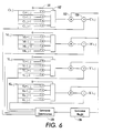
- Figure 6 illustrates a block diagram of the system components for the invention.
- each of its CMYK color components should be the maximum of corresponding component values of the two region colors, but this not always necessary or desirable. Picking the maximum component values can give a dark border color and can draw attention to the boundary. An altemative is to use a value somewhere between the maximum and minimum values for each component. Using an intermediate value can make the boundary less conspicuous and still fill in any gaps with some color darker than white. (One must be a little careful here to also consider the halftoning since a light color in a coarse halftone may appear as a chain of spots within the gap and may draw attention to the gap rather than reduce its visibility.)
- Cyan 6, for example is a constant color level within the image.
- Magenta 8 on the other hand is changing. The method modifies the magenta changes 7 according to each pixel's value and the values of its neighbors. Note that bigger changes 7 over the corresponding steps 5 in Figure 3 are reflected because of the presence of cyan 6 as a constant, which reduces the amount of luminance in all pixels for Figure 4.
- magenta 10 is largely represented in the area to the left of the edge 11, but then falls to a lower value on the right of the edge 11.
- Cyan 9 takes an opposite approach in the graph, transitioning from a lower value on the left to a higher value on the right.
- low luminance on each side of the edge 11 provide for strong change in cyan correction 13 on the magenta side and magenta correction 12 on the cyan side of the example image.
- This method is intended for images that have been rendered to continuous-tone rasters. It does not require knowledge of particular graphic objects or their shapes. It can be used with digital copiers as well as printers. It can be applied when the image is complete and avoids the problems of trapping along artificial boundaries that are later removed. This situation can arise when an object is constructed from several components (e.g. when a sweep is constructed from a series of rectangles.)
- Cia is the positive difference as calculated above between pixel a and its ith neighbor (Note that an equivalent calculation is to find the maximum of differences for a color separation for all neighbors and then take the maximum of this result with zero.).
- Mx , Yx and Kx We are going to modify or replace the value of pixel a . If pixel a is in a region of uniform color our modifications will leave its value unchanged. If, however, pixel a lies on the boundary between two regions we will change its color to supply trapping to that boundary.
- the invention can be carried out with hardware as illustrated in the block diagram of Figure 6.
- the system has a means to determine the value of the fraction based on neighboring pixel luminance.
- the system determines pixel luminance which is utilized to determine the optimum neighboring value that should be added to protect against misregistration.
- the left side of figure 6 shows the input of the color-component values for the pixel at location i, j (i.e. Ci,j, Mi,j, Yi,j, Ki,j).
- the values for neighboring pixels are also input; for example, the cyan components for the neighboring pixels are Ci+1,j, Ci-1,j, Ci,j+1, Ci,j-1.
- the differences between the pixel value and the values of its neighbors e.g.
- Ci+1,j - Ci,j are determined in input modules 101. Calculation of the maximum value of the four differences and zero is provided within the comparing modules 102 for each input. The original pixel values are also fed to a luminance calculating module 105 that determines an approximate luminance value and feeds this to weight generating module 106. Note that module 106 may be implemented as a simple look-up table. The maximum differences are then scaled by the weight at scale modules 103 for the four colors. This scaled result is then added to the original colorant values at summing modules 104 to give the modified colorant amount for each output.
- the invention can also be carried out in a microprocessor-based system that is programmed to determined he component-wise maximum color differences for pixels from neighboring pixels and adding a fraction of the difference to the pixels color values.
- the system is programmable to utilize up to two pixels wide for four immediately adjacent pixels as a pixel neighborhood during trapping involving a region up to two pixels wide. For wider trapping regions a system can be developed based on the teachings herein that can use the 8, 12, 20 or 24 neighbors.
Landscapes
- Engineering & Computer Science (AREA)
- Multimedia (AREA)
- Signal Processing (AREA)
- Facsimile Image Signal Circuits (AREA)
- Image Processing (AREA)
- Color Image Communication Systems (AREA)
- Color, Gradation (AREA)
Applications Claiming Priority (2)
| Application Number | Priority Date | Filing Date | Title |
|---|---|---|---|
| US4282 | 1998-01-08 | ||
| US09/004,282 US6236754B1 (en) | 1998-01-08 | 1998-01-08 | Image modification to reduce susceptibility to misregistration |
Publications (3)
| Publication Number | Publication Date |
|---|---|
| EP0929189A2 true EP0929189A2 (fr) | 1999-07-14 |
| EP0929189A3 EP0929189A3 (fr) | 2001-07-25 |
| EP0929189B1 EP0929189B1 (fr) | 2003-08-27 |
Family
ID=21710018
Family Applications (1)
| Application Number | Title | Priority Date | Filing Date |
|---|---|---|---|
| EP99100109A Expired - Lifetime EP0929189B1 (fr) | 1998-01-08 | 1999-01-04 | Modification d'image pour réduire la susceptibilité de désalignement |
Country Status (4)
| Country | Link |
|---|---|
| US (1) | US6236754B1 (fr) |
| EP (1) | EP0929189B1 (fr) |
| JP (1) | JPH11286146A (fr) |
| DE (1) | DE69910631T2 (fr) |
Cited By (8)
| Publication number | Priority date | Publication date | Assignee | Title |
|---|---|---|---|---|
| DE19912511A1 (de) * | 1999-03-19 | 2000-09-21 | Heidelberger Druckmasch Ag | Verfahren zur Erzeugung von Überfüllungskonturen in einer Druckseite |
| WO2003051035A1 (fr) | 2001-10-02 | 2003-06-19 | Hewlett-Packard Company | Reduction d'artefacts de diffusion chromatiques dans des images |
| EP1107178A3 (fr) * | 1999-11-30 | 2004-02-04 | Xerox Corporation | Correction des bordures de couleur par gradients à l'aide des zones texturées |
| DE102004062841A1 (de) * | 2004-12-27 | 2006-07-13 | OCé PRINTING SYSTEMS GMBH | Verfahren, Computerprogramm, Computer und Drucksysteme zum Trapping von Bilddaten |
| DE102006008768A1 (de) * | 2006-02-24 | 2007-08-30 | OCé PRINTING SYSTEMS GMBH | Verfahren und Vorrichtung zum Verarbeiten eines Druckdatenstroms zum Erzeugen mehrfarbiger Druckbilder mit Hilfe eines Hochleistungsdrucksystems |
| US7623706B1 (en) | 2000-09-29 | 2009-11-24 | Hewlett-Packard Development Company, L.P. | Reduction of chromatic bleeding artifacts in images containing subsampled chrominance values |
| US7817305B2 (en) | 2006-11-24 | 2010-10-19 | Oce Printing Systems Gmbh | Method, computer program and printing system for trapping of print data |
| US8705136B2 (en) | 2006-11-24 | 2014-04-22 | OCé PRINTING SYSTEMS GMBH | Method, computer program and print system for trapping print data |
Families Citing this family (21)
| Publication number | Priority date | Publication date | Assignee | Title |
|---|---|---|---|---|
| DE19735380C1 (de) * | 1997-08-14 | 1999-04-08 | Peter T Speck | Verfahren und Vorrichtung zum Aufbereiten einer aus Bildelementen bestehenden Ausgangsvorlage |
| US6697078B2 (en) * | 1999-01-29 | 2004-02-24 | Adobe Systems Incorporated | Trap shaping |
| US7187471B1 (en) | 1999-12-09 | 2007-03-06 | Adobe Systems Incorporated | Creating traps with asymmetric widths |
| US6987585B1 (en) * | 2000-09-27 | 2006-01-17 | Adobe Systems Incorporated | Trap shaping using a miter equation |
| US7116821B2 (en) * | 2002-03-25 | 2006-10-03 | Lexmark International, Inc. | Color trapping for an image forming apparatus |
| US7256910B2 (en) * | 2002-04-23 | 2007-08-14 | Weyerhaeuser Company | Color separation method and printed product of the method |
| US7382494B2 (en) * | 2003-06-27 | 2008-06-03 | Xerox Corporation | Method for tag plane growth and contraction for improving object edge rendering |
| US7242415B1 (en) * | 2004-02-25 | 2007-07-10 | Adobe Systems Incorporated | Processing illustrations using stored information |
| US20060033961A1 (en) * | 2004-08-13 | 2006-02-16 | Quark, Inc. | Systems and methods for small element trapping |
| US20060087698A1 (en) * | 2004-08-13 | 2006-04-27 | Quark, Inc. | Systems and methods for variable trapping |
| US20060033971A1 (en) * | 2004-08-13 | 2006-02-16 | Quark, Inc. | Automated trapping system for desktop publishing |
| US20060033960A1 (en) * | 2004-08-13 | 2006-02-16 | Quark, Inc. | Systems and methods for ink selection in the trapping zone |
| US20060087697A1 (en) * | 2004-08-13 | 2006-04-27 | Quark, Inc. | Systems and methods for recursive trapping |
| US7609269B2 (en) * | 2006-05-04 | 2009-10-27 | Microsoft Corporation | Assigning color values to pixels based on object structure |
| US8339411B2 (en) * | 2006-05-04 | 2012-12-25 | Microsoft Corporation | Assigning color values to pixels based on object structure |
| US7777758B2 (en) * | 2006-10-10 | 2010-08-17 | Adobe Systems Incorporated | Automatic trapping of drop shadows |
| US8432572B2 (en) * | 2007-06-29 | 2013-04-30 | Konica Minolta Laboratory U.S.A., Inc. | Systems and methods of trapping for print devices |
| US8570340B2 (en) | 2008-03-31 | 2013-10-29 | Konica Minolta Laboratory U.S.A., Inc. | Systems and methods for data compression |
| US8699042B2 (en) * | 2008-06-12 | 2014-04-15 | Konica Minolta Laboratory U.S.A., Inc. | Systems and methods for multi-mode color blending |
| DE102008037708B4 (de) | 2008-08-14 | 2014-05-28 | Krones Aktiengesellschaft | Verfahren und Vorrichtung zum Behandeln von Getränkebehältnissen |
| US8995021B2 (en) | 2013-06-12 | 2015-03-31 | Xerox Corporation | Black trapping methods, apparatus and systems for binary images |
Family Cites Families (24)
| Publication number | Priority date | Publication date | Assignee | Title |
|---|---|---|---|---|
| DE3266655D1 (en) | 1982-06-04 | 1985-11-07 | Hell Rudolf Dr Ing Gmbh | Process to avoid image defects in multicolour printing caused by non coincident printing of the colour separations |
| GB8410860D0 (en) | 1984-04-27 | 1984-06-06 | Crosfield Electronics Ltd | Image modification |
| JP2677283B2 (ja) | 1984-06-14 | 1997-11-17 | キヤノン株式会社 | カラー画像処理装置 |
| GB8500494D0 (en) * | 1985-01-09 | 1985-02-13 | Crosfield Electronics Ltd | Image enhancement |
| JPH01170169A (ja) | 1987-12-25 | 1989-07-05 | Dainippon Screen Mfg Co Ltd | 多色印刷のための画像図形修正処理方法 |
| JPH02253765A (ja) * | 1989-03-28 | 1990-10-12 | Toshiba Corp | 画像処理装置 |
| JP3117448B2 (ja) | 1989-10-12 | 2000-12-11 | 株式会社日立製作所 | カラー画像記録方法とその装置 |
| IL93607A (en) | 1990-03-02 | 1997-09-30 | Scitex Corp Ltd | Method and system for preparing polychromatic printing plates |
| JP2528376B2 (ja) | 1990-06-28 | 1996-08-28 | 大日本スクリーン製造株式会社 | 画像の輪郭修正方法 |
| US5131058A (en) | 1990-08-24 | 1992-07-14 | Eastman Kodak Company | Method for obtaining output-adjusted color separations |
| JPH0817445B2 (ja) * | 1990-11-06 | 1996-02-21 | 大日本スクリーン製造株式会社 | 画像のカブセ処理方法 |
| US5295236A (en) | 1991-03-04 | 1994-03-15 | Aldus Corporation | Applying traps to a printed page specified in a page description language format |
| US5542052A (en) | 1991-03-04 | 1996-07-30 | Adobe Systems Incorporated | Applying traps to a printed page specified in a page description language format |
| US5402530A (en) | 1991-08-20 | 1995-03-28 | Island Graphics Corporation | Method and system for color film separation preprocess using electronic object-based choking and spreading procedures including object combining operations |
| US5241396A (en) | 1991-09-16 | 1993-08-31 | Xerox Corporation | Color printing yielding a dense black image |
| JP2639518B2 (ja) | 1991-10-30 | 1997-08-13 | 大日本スクリーン製造株式会社 | 画像処理方法 |
| US5513200A (en) | 1992-09-22 | 1996-04-30 | Xerox Corporation | Monolithic array of independently addressable diode lasers |
| US5313570A (en) | 1993-03-31 | 1994-05-17 | Miles, Inc. | Method for determining color boundaries for correcting for plate misregistration in color printing |
| US5613046A (en) | 1993-03-31 | 1997-03-18 | Miles Inc. | Method and apparatus for correcting for plate misregistration in color printing |
| US5668931A (en) | 1993-03-31 | 1997-09-16 | Dermer; Richard A. | Method for automatic trap selection for correcting for plate misregistration in color printing |
| US5440652A (en) | 1993-09-10 | 1995-08-08 | Athena Design Systems, Inc. | Method and apparatus for preparing color separations based on n-way color relationships |
| US5666543A (en) | 1994-03-23 | 1997-09-09 | Adobe Systems Incorporated | Method of trapping graphical objects in a desktop publishing program |
| US5615314A (en) | 1994-08-30 | 1997-03-25 | Management Graphics, Inc. | Interface for providing rasterized data to an imaging device |
| US5581667A (en) * | 1994-12-23 | 1996-12-03 | Xerox Corporation | Electronic trapping system for digitized text and images |
-
1998
- 1998-01-08 US US09/004,282 patent/US6236754B1/en not_active Expired - Lifetime
-
1999
- 1999-01-04 EP EP99100109A patent/EP0929189B1/fr not_active Expired - Lifetime
- 1999-01-04 DE DE69910631T patent/DE69910631T2/de not_active Expired - Lifetime
- 1999-01-04 JP JP11000022A patent/JPH11286146A/ja active Pending
Cited By (12)
| Publication number | Priority date | Publication date | Assignee | Title |
|---|---|---|---|---|
| DE19912511A1 (de) * | 1999-03-19 | 2000-09-21 | Heidelberger Druckmasch Ag | Verfahren zur Erzeugung von Überfüllungskonturen in einer Druckseite |
| US6795214B2 (en) | 1999-03-19 | 2004-09-21 | Heidelberger Druckmaschinen Ag | Method for generating trapping contours in a print page |
| EP1107178A3 (fr) * | 1999-11-30 | 2004-02-04 | Xerox Corporation | Correction des bordures de couleur par gradients à l'aide des zones texturées |
| US6781720B1 (en) | 1999-11-30 | 2004-08-24 | Xerox Corporation | Gradient-based trapping using patterned trap zones |
| US7623706B1 (en) | 2000-09-29 | 2009-11-24 | Hewlett-Packard Development Company, L.P. | Reduction of chromatic bleeding artifacts in images containing subsampled chrominance values |
| WO2003051035A1 (fr) | 2001-10-02 | 2003-06-19 | Hewlett-Packard Company | Reduction d'artefacts de diffusion chromatiques dans des images |
| DE102004062841A1 (de) * | 2004-12-27 | 2006-07-13 | OCé PRINTING SYSTEMS GMBH | Verfahren, Computerprogramm, Computer und Drucksysteme zum Trapping von Bilddaten |
| US7856140B2 (en) | 2004-12-27 | 2010-12-21 | Oce Printing Systems Gmbh | Method, computer program, computer and printing system for trapping image data |
| DE102006008768A1 (de) * | 2006-02-24 | 2007-08-30 | OCé PRINTING SYSTEMS GMBH | Verfahren und Vorrichtung zum Verarbeiten eines Druckdatenstroms zum Erzeugen mehrfarbiger Druckbilder mit Hilfe eines Hochleistungsdrucksystems |
| US8085439B2 (en) | 2006-02-24 | 2011-12-27 | Oce Printing Systems Gmbh | Method and device for processing a print data flow for producing multicolor printed images using a high performance printing system |
| US7817305B2 (en) | 2006-11-24 | 2010-10-19 | Oce Printing Systems Gmbh | Method, computer program and printing system for trapping of print data |
| US8705136B2 (en) | 2006-11-24 | 2014-04-22 | OCé PRINTING SYSTEMS GMBH | Method, computer program and print system for trapping print data |
Also Published As
| Publication number | Publication date |
|---|---|
| EP0929189B1 (fr) | 2003-08-27 |
| DE69910631D1 (de) | 2003-10-02 |
| JPH11286146A (ja) | 1999-10-19 |
| US6236754B1 (en) | 2001-05-22 |
| EP0929189A3 (fr) | 2001-07-25 |
| DE69910631T2 (de) | 2004-02-19 |
Similar Documents
| Publication | Publication Date | Title |
|---|---|---|
| US6236754B1 (en) | Image modification to reduce susceptibility to misregistration | |
| US7123381B2 (en) | System and method of trapping for correcting for separation misregistration in color printing | |
| US6345117B2 (en) | Method for automatic trap selection for correcting for separation misregistration in color printing | |
| US6781720B1 (en) | Gradient-based trapping using patterned trap zones | |
| EP0618718B1 (fr) | Correction d'une fausse régistration de plaques pour impression en couleurs d'images définies dans une langue descriptive de pages | |
| EP0415648B1 (fr) | Appareil de traitement d'images | |
| US6504949B2 (en) | Image processing apparatus and method | |
| US7148997B2 (en) | Image processing apparatus and method | |
| US8593694B2 (en) | Image processing apparatus and its method | |
| EP0620534B1 (fr) | Procédé pour déterminer automatiquement des bordures de couleur pour corriger une fausse régistration de plaques d'impression en coulours | |
| EP1014694B1 (fr) | Amélioration automatique de la qualité d'impression basée sur la dimension, la forme, l'orientation et la couleur d'une structure | |
| EP1073260B1 (fr) | Dispositif de traitement d'images, dispositif de formation d'images incorporant celui-ci, et support de stockage dans lequel un programme utilisé par celui-ci est stocké | |
| JP4172616B2 (ja) | 画像処理装置 | |
| US7173738B2 (en) | Method of producing traps in a print page | |
| JP4329271B2 (ja) | 画像処理装置、画像形成装置、および画像処理方法 | |
| JP4404459B2 (ja) | 局所的に調節されたハーフトーンを用いてカラー画像を印刷する方法及び装置 | |
| US6760127B1 (en) | Multi-level semi-vector error diffusion | |
| US6972866B1 (en) | Detecting process neutral colors | |
| EP0996281A2 (fr) | Procédé et système de traitement d'image en couleur | |
| JP3796985B2 (ja) | 画像処理装置、画像処理方法および記憶媒体 | |
| JP2672553B2 (ja) | 画像処理装置 | |
| JP3770802B2 (ja) | 画像処理方法、画像処理装置及び画像形成装置 | |
| EP1605684A1 (fr) | Procédé de traitement d'une image numérique pour l'amélioration de la partie texte de cette image | |
| JPH09322007A (ja) | カラー画像処理装置及び方法 |
Legal Events
| Date | Code | Title | Description |
|---|---|---|---|
| PUAI | Public reference made under article 153(3) epc to a published international application that has entered the european phase |
Free format text: ORIGINAL CODE: 0009012 |
|
| AK | Designated contracting states |
Kind code of ref document: A2 Designated state(s): DE FR GB |
|
| AX | Request for extension of the european patent |
Free format text: AL;LT;LV;MK;RO;SI |
|
| PUAL | Search report despatched |
Free format text: ORIGINAL CODE: 0009013 |
|
| AK | Designated contracting states |
Kind code of ref document: A3 Designated state(s): AT BE CH CY DE DK ES FI FR GB GR IE IT LI LU MC NL PT SE |
|
| AX | Request for extension of the european patent |
Free format text: AL;LT;LV;MK;RO;SI |
|
| 17P | Request for examination filed |
Effective date: 20020125 |
|
| AKX | Designation fees paid |
Free format text: DE FR GB |
|
| 17Q | First examination report despatched |
Effective date: 20020723 |
|
| GRAH | Despatch of communication of intention to grant a patent |
Free format text: ORIGINAL CODE: EPIDOS IGRA |
|
| GRAS | Grant fee paid |
Free format text: ORIGINAL CODE: EPIDOSNIGR3 |
|
| GRAA | (expected) grant |
Free format text: ORIGINAL CODE: 0009210 |
|
| AK | Designated contracting states |
Designated state(s): DE FR GB |
|
| REG | Reference to a national code |
Ref country code: GB Ref legal event code: FG4D |
|
| REF | Corresponds to: |
Ref document number: 69910631 Country of ref document: DE Date of ref document: 20031002 Kind code of ref document: P |
|
| ET | Fr: translation filed | ||
| PLBE | No opposition filed within time limit |
Free format text: ORIGINAL CODE: 0009261 |
|
| STAA | Information on the status of an ep patent application or granted ep patent |
Free format text: STATUS: NO OPPOSITION FILED WITHIN TIME LIMIT |
|
| 26N | No opposition filed |
Effective date: 20040528 |
|
| REG | Reference to a national code |
Ref country code: GB Ref legal event code: 746 Effective date: 20041130 |
|
| REG | Reference to a national code |
Ref country code: FR Ref legal event code: D6 |
|
| REG | Reference to a national code |
Ref country code: FR Ref legal event code: PLFP Year of fee payment: 18 |
|
| PGFP | Annual fee paid to national office [announced via postgrant information from national office to epo] |
Ref country code: GB Payment date: 20151224 Year of fee payment: 18 |
|
| PGFP | Annual fee paid to national office [announced via postgrant information from national office to epo] |
Ref country code: FR Payment date: 20151222 Year of fee payment: 18 |
|
| PGFP | Annual fee paid to national office [announced via postgrant information from national office to epo] |
Ref country code: DE Payment date: 20151217 Year of fee payment: 18 |
|
| REG | Reference to a national code |
Ref country code: DE Ref legal event code: R119 Ref document number: 69910631 Country of ref document: DE |
|
| GBPC | Gb: european patent ceased through non-payment of renewal fee |
Effective date: 20170104 |
|
| REG | Reference to a national code |
Ref country code: FR Ref legal event code: ST Effective date: 20170929 |
|
| PG25 | Lapsed in a contracting state [announced via postgrant information from national office to epo] |
Ref country code: FR Free format text: LAPSE BECAUSE OF NON-PAYMENT OF DUE FEES Effective date: 20170131 |
|
| PG25 | Lapsed in a contracting state [announced via postgrant information from national office to epo] |
Ref country code: GB Free format text: LAPSE BECAUSE OF NON-PAYMENT OF DUE FEES Effective date: 20170104 Ref country code: DE Free format text: LAPSE BECAUSE OF NON-PAYMENT OF DUE FEES Effective date: 20170801 |