EP0929435B1 - Hebe-vorrichtung für eine handkarre - Google Patents
Hebe-vorrichtung für eine handkarre Download PDFInfo
- Publication number
- EP0929435B1 EP0929435B1 EP96932406A EP96932406A EP0929435B1 EP 0929435 B1 EP0929435 B1 EP 0929435B1 EP 96932406 A EP96932406 A EP 96932406A EP 96932406 A EP96932406 A EP 96932406A EP 0929435 B1 EP0929435 B1 EP 0929435B1
- Authority
- EP
- European Patent Office
- Prior art keywords
- main body
- body portion
- combination
- extension leg
- threaded rod
- Prior art date
- Legal status (The legal status is an assumption and is not a legal conclusion. Google has not performed a legal analysis and makes no representation as to the accuracy of the status listed.)
- Expired - Lifetime
Links
- 230000003028 elevating effect Effects 0.000 title claims abstract description 60
- 230000002441 reversible effect Effects 0.000 claims abstract description 8
- 230000000903 blocking effect Effects 0.000 claims description 11
- 210000000352 storage cell Anatomy 0.000 claims description 10
- 230000003134 recirculating effect Effects 0.000 claims description 4
- 125000006850 spacer group Chemical group 0.000 claims description 4
- 230000006872 improvement Effects 0.000 claims description 2
- 238000011065 in-situ storage Methods 0.000 claims description 2
- 230000008901 benefit Effects 0.000 description 2
- 230000005484 gravity Effects 0.000 description 2
- 238000004519 manufacturing process Methods 0.000 description 2
- 238000000034 method Methods 0.000 description 2
- 238000012986 modification Methods 0.000 description 2
- 230000004048 modification Effects 0.000 description 2
- 229910000861 Mg alloy Inorganic materials 0.000 description 1
- 230000004075 alteration Effects 0.000 description 1
- XAGFODPZIPBFFR-UHFFFAOYSA-N aluminium Chemical compound [Al] XAGFODPZIPBFFR-UHFFFAOYSA-N 0.000 description 1
- 229910052782 aluminium Inorganic materials 0.000 description 1
- SNAAJJQQZSMGQD-UHFFFAOYSA-N aluminum magnesium Chemical compound [Mg].[Al] SNAAJJQQZSMGQD-UHFFFAOYSA-N 0.000 description 1
- 230000003190 augmentative effect Effects 0.000 description 1
- 230000000295 complement effect Effects 0.000 description 1
- 231100001261 hazardous Toxicity 0.000 description 1
- 239000000463 material Substances 0.000 description 1
- 230000007246 mechanism Effects 0.000 description 1
- 230000007935 neutral effect Effects 0.000 description 1
- 238000009877 rendering Methods 0.000 description 1
- 230000000284 resting effect Effects 0.000 description 1
Images




Classifications
-
- B—PERFORMING OPERATIONS; TRANSPORTING
- B62—LAND VEHICLES FOR TRAVELLING OTHERWISE THAN ON RAILS
- B62B—HAND-PROPELLED VEHICLES, e.g. HAND CARTS OR PERAMBULATORS; SLEDGES
- B62B5/00—Accessories or details specially adapted for hand carts
- B62B5/02—Accessories or details specially adapted for hand carts providing for travelling up or down a flight of stairs
- B62B5/023—Accessories or details specially adapted for hand carts providing for travelling up or down a flight of stairs using an upwards pushing device
Definitions
- This invention relates to elevating units for attachment to manual hand trucks, and more particularly, to such elevating units that are readily mountable on and removable from existing manual hand trucks.
- extension legs and associated drive mechanism that form an integral part of such prior art powered hand trucks tend to make them heavy, which is undesirable for the easy and safe manoeuvring of the hand truck and payload.
- acceptance of such powered hand trucks has met with resistance, particularly with regard to those operators who would be required to replace a large inventory of existing manual hand trucks with new, expensive power models, thus rendering their investment in the manual hand trucks of little residual value.
- An example of such an operator would be a large courier or cartage company who might own, in some instances, thousands of manual hand carts.
- an improved elevating unit for use in combination with a hand truck.
- the hand truck has a frame extending in a substantially vertical direction from a lower end to an upper end and extending laterally from a left side to a right side, upper and lower cross-members extending substantially between said left and right sides of said frame, a handle means disposed adjacent said upper end, a front side and a back side, with a payload supporting surface extending forwardly from said front side, and a pair of wheels operatively mounted on said frame adjacent the lower end thereof for rotation about a common lateral axis;
- the elevating unit has a main body portion having a front side and a back side, an extension leg having a foot portion and being operatively mounted on said main body portion for selectively controlled movement between a first extended position whereat said foot portion is disposed below said lower end of said frame and a second retracted position whereat said foot portion is raised from being disposed below said lower end of said frame, drive means operatively coupled to
- the improvement to the combination of the invention comprises the provision of a first bracket means mounted on the main body portion in disposed relation to said front side of said main body portion for readily removable secured engagement of the main body portion to the upper cross-member of the hand truck, the first bracket means being substantially C-shaped in cross section, defining a forwardly facing opening, with a lower arm of the C-shape forming a load bearing portion, and with an upper arm of the C-shape forming a weight transmitting portion for transmitting a portion of the weight of said elevating unit to said upper cross-member.
- the upper and lower arm portions are spaced apart sufficiently to receive the upper cross-member there between.
- a channel blocking means is provided that is readily movable between a first blocking position, whereat the channel blocking means occludes the opening to thereby hold the upper cross-member in operative, secured relation, and a second open position whereat the channel blocking means is removed from occluding the opening, to thereby provide for ingress and egress of the upper cross-member.
- a second bracket means is rigidly mounted on the main body portion in disposed relation to the back side of the main body portion for readily removable secured engagement of the main body portion to the lower cross-member, the second bracket means comprising a weight transmitting portion shaped and dimensioned to rest on the lower cross-member in weight transmitting relation for transmitting a portion of the weight of the elevating unit to the lower cross-member.
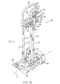
- FIG. 1 through 7A Figures show the elevating unit of the present invention, as indicated by general reference numeral 20, for attachment to a conventional manual hand truck, as indicated by the general reference numeral 22.
- a conventional manual hand truck is that available under the trademark MAGLINER from MAGLINE INC. of Pinconning, Michigan, 48680 U.S.A..
- Such a hand truck 22 has a frame 24 extending in a substantially vertical direction from a lower end 26 to an upper end 28, and extending laterally from a left side 30 to a right side 32.
- An upper cross-member 34 and a lower cross-member 36 extend substantially between the left 30 and right 32 sides of the frame 24.
- the hand truck 22 has a front side 40 and a back side 42.
- a payload supporting surface 44 extends forwardly from the front side 40, and a pair of wheels 46 are operatively mounted on the crane 24 adjacently lower end 26 thereof, for rotation about a common lateral axis "L".
- the elevating unit 20 comprises, when in place on the hand truck 22, a main body portion 50 having a front side 52 and a back side 54.
- the main body portion 50 essentially houses most of the moving components of the elevating unit 20, and is made of a strong yet light material, such as aluminum, or an aluminum-magnesium alloy.
- a pair of oppositely directed rubber covered grip handle members 56, 57 each extend outwardly from a base portion 58.
- An extension leg 60 having a foot portion 62 disposed at the bottom end 63 thereof, is operatively mounted within the main body portion 50 for selectively controlled movement between a first extended position and a second retracted position.
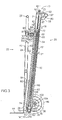
- the extension leg 60 comprises a hollow tube 64 having a substantially square cross-section and is elongate along a first longitudinal axis "A", as can be best seen in Figures 3 and 4.
- the extension leg 60 is disposed in sliding relation within the main body portion 50.
- a slide bearing means in the form of a first slide bearing assembly 76 and a second slide bearing assembly 78, is disposed in operative relation between the extension leg 60 and the main body portion 50.
- the first slide bearing assembly 76 is mounted on the extension leg 60 adjacent the top end 61 thereof for sliding engagement with the main body portion 50.
- the second slide bearing assembly 78 is mounted on the main body portion 50 adjacent the bottom end 53 thereof.
- the extension leg 60 is substantially vertically disposed when in its first extended position and in its second retracted position, and moves linearly along its first longitudinal axis "A" when moving between its first extended position and its second retracted position.
- the foot portion 62 has a rubber pad 65 on the bottom thereof for the purpose of augmenting traction of the foot portion 62.
- the foot portion 62 In the first extended position, the foot portion 62 is disposed below the lower end 26 of the frame 24. In the second retracted position, the foot portion 62 is raised from being disposed below the lower end 26 of the frame 24.
- a drive means is operatively coupled to the extension leg 60 to selectively move the extension leg 60 in a first direction, as indicated by arrow "C” of Figure 5, to the first extended position, and in a second direction, as indicated by arrow “D” of Figure 5, from the first extended position to the second retracted position.
- the drive means 70 preferably comprises a substantially vertically disposed elongate threaded rod 71 having a second longitudinal axis "B" substantially aligned with the first longitudinal axis "A" (see Figures 3 and 4).
- the elongate threaded rod 71 is operatively mounted within the main body portion 50 by means of a first rotational bearing 73 disposed at the top of the main body portion 50 and a second rotational bearing 74 disposed at the bottom of the threaded rod 71, for rotation in opposed first and second rotational directions, as indicated by arrows "F" and “S” in Figure 3, respectively, about the second longitudinal axis "B".
- the second rotational bearing 74 is disposed within a third slide bearing 79 so as to retain the threaded rod 71 in sliding relation with respect to the extension leg 60, and also to preclude lateral movement of the threaded rod 71 within the extension leg 60.
- a recirculating ball nut 72 is threadibly engaged on the elongate threaded rod 71 for movement along the length thereof as the threaded rod 71 rotates.
- the extension leg 60 is secured to the recirculating ball nut 72 for movement therewith as aforesaid, in surrounding relation to the threaded rod 71.
- Rotation of the threaded rod 71 in its first rotational direction “F” causes corresponding linear movement of the extension leg 60 in its first direction "C” towards its first extended position.
- Rotation of the threaded rod 71 in its second rotational direction “S” causes corresponding linear movement of the extension leg 60 in its second direction "D", toward its second retracted position.
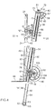
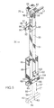
- the drive means 70 further comprises a motor means in the form of an electrically energizable reversible motor 80 operatively connected in driving relation to the elongate threaded rod 71 by means of a drive chain 81, as can be best seen in Figures 2, 3, and 4, to rotate the elongate rod 71 in the opposed first "F" and second "S" rotational directions.
- the electrically energizable motor 80 is mounted at the top end 51 of the main body portion 50 at either the left side or the right side thereof, so as to not be in the way of the frame 24 of the hand truck 22, or in the way of an operator of the elevating unit 20.
- a guard member 88 is mounted over the drive chain 81, as can be seen in Figures 1A, 1B, 5, 6A - 6E, 7A, and 7B.
- a control means 81 is operatively coupled to the drive means 70 to permit selective actuation of the drive means 70 in its first rotational direction, as indicated by arrow "F", and its second rotational direction as indicated by arrow "S".
- the control means 81 comprises a three-position electrical switch 82 connected in selective electrically conductive relation between an electrical power source, such as an electrical power storage cell 84, by a first electrical cable 87, and the electrically energizable motor 80 by a second electrical cable 83 (see Figures 3 and 4).
- an electrical power source such as an electrical power storage cell 84
- the electrically energizable motor 80 by a second electrical cable 83 (see Figures 3 and 4).
- the reversible motor 80 When the three-position electrical switch 82 is in its second position, the reversible motor 80 is energized so as to cause the threaded rod 71 to rotate in its second opposite rotational direction "F". When the three-position electrical switch is in its third position, which third position is preferably a central position, the reversible motor 80 is not energized, thus precluding the threaded rod 71 from rotating.
- the electrical power storage cell 84 is mounted in an enclosure 85 in order to cover the storage cell 84 for safety reasons and also to preclude damage to the electrical power storage cell 84.
- the enclosure 85, and therefore the electrical power storage cell 84 are located adjacent the bottom end 53 of the main body portion 50 so as to help provide for a low centre of gravity of the elevating unit 20, as the electrical power storage cell 84 is typically somewhat heavy.
- the electrical power storage cell 84 is rechargeable in situ by means of a conventional electrical cord (not shown) plugged into a receiving socket 86 mounted in a side wall of enclosure 85.
- the electrical power storage cell 84 can thereby be readily recharged when it is not in use, such as when it is in a delivery truck 21 (see Figures 7A and 7B).
- the elevating unit 20 would be not in use while the delivery truck 21 is on route between delivery destinations, or in the event the elevating unit 20 is not needed to help negotiate the hand truck 22 onto or off of the delivery truck 21 or up or down a set of stairs.
- a first bracket means 90 is mounted on the main body portion 50 of the elevating device 20 for removable secure engagement of the main body portion 50 to the upper cross-member 34 of the manual hand truck 22 by means of a brace bracket 95 and threaded fasteners 97.
- the first bracket means 90 is disposed at the front side 52 of the main body portion 50 of the elevating unit 20.
- the first bracket means 90 comprises a load bearing portion 92 shaped and dimensioned to receive the upper cross-member 34 in load bearing relation thereon, and a weight transmitting portion 94 shaped and dimensioned to rest on the upper cross-member 34 in weight transmitting relation so as to transmit a portion of the weight of the elevating unit to the upper cross-menmber 34.
- the first bracket means 90 is substantially “C”-shaped in cross-section, defining a forwardly facing opening 96.
- the lower arm of the "C"-shaped bracket means 90 forms a portion of the load bearing portion 92.
- the upper arm of the "C”-shaped bracket means 90 forms a portion of the weight transmitting portion 94.
- the load bearing portion 92 and the weight transmitting portion 94 are spaced apart sufficiently by a distance "E" so as to receive the upper cross-member 34 therebetween, as can best be seen in Figures 3 and 4.
- the elevating unit 20 must support the entire load of the hand truck 22 and a payload 25 thereon disposed on the payload supporting surface 44.
- the load of the hand truck 22 and the payload 25 thereon is borne directly by the load bearing portion 92 of the first bracket means 90.
- the foot 62 when the extension legs 60 is in its second retracted position, the foot 62 is not in position to be in contact with the ground, a floor, or the like.
- the wheels 46 of the hand truck 22 are then in contact with the ground, or the floor, or the like, and support the hand truck 22 and a payload 25 thereon.
- the hand truck 22 also supports the weight of the elevating unit 20 through the weight transmitting portion 94 of the first bracket means 90.
- a channel blocking means in the form of two cooperating pins 91, is moveable between a first blocking position and a second open position.
- the pins 91 In the first blocking position, the pins 91 each engage aligned apertures 93 in the load bearing portion 92 and the weight transmitting portion 94 of the first bracket means 90.
- the pins 91 are held in place by gravity, so as to occlude the opening 96, thereby holding the upper cross-member 34 in operative, secured relation within the opening 96.
- the pins 91 are removed from the apertures 93, and thereby removed from occluding the opening 96, to thereby provide ingress and egress of the upper cross-member 34.
- Conventional spring-loaded pins having discrete open and closed positioned may be routinely substituted for the simple pins 91 shown.
- a second bracket means 100 is mounted to the main body portion 50 adjacent its lower end for removable secure engagement of the main body portion to the lower cross-member 36.
- the second bracket means 100 comprises a weight transmitting portion 102 shaped and dimensioned to rest on the lower cross-member 36 in weight transmitting relation, for transmitting a portion of the weight of said elevating unit to said lower cross memeber 36.
- the second bracket means 100 further comprises a flange portion 104 (see Figures 3 and 4) depending from the weight transmitting portion 102, such that the flange portion 104, the weight transmitting portion 102, and the main body portion 50 together form a downwardly open generally "U"-shaped channel dimensioned to receive the lower cross-member 36 therein.
- the lower cross-member 36 comprises an axle member defining a common lateral axis "L", with a pair of spacer members 106 disposed in surrounding relation around the axle member 36.
- the spacer members 106 are spaced apart one from the other on the axle member 36 by a centrally disposed gap 108 (see Figure 1A).
- the second bracket means 100 engages the axle member 36 at the gap 108.
- the foot portion 62 of the extension leg 60 is positioned between the axle 36 and the frame 24 of the hand truck 22, as indicated by arrow "I" in Figure 1A.
- the second bracket means 100 rests on the axle 36 of the hand truck 22 in the gap 108.
- the elevating unit 20 is then pushed forwardly at its top so as to pivot about the axle 36, such that the first bracket means 90 moves forwardly towards the upper cross-member 34, until the upper cross-member 34 enters the opening in the substantially "C"-shaped first bracket 90.
- Pins 91 are then put into place in apertures 93, so as to occlude the opening 96, thereby holding the upper cross-member 34 in operative secured relation.
- Attachment of the elevating unit 20 to the manual hand truck 22 is quick and easy, thus allowing an operator of the manual hand truck 22 to include and use the elevating unit 20, as desired, or to not include and not use the elevating unit 20, as desired, without a significant amount of time investment required for attachment and subsequent removal of the elevating unit 20.
- Such selective use of the elevating unit 20 to assist the manipulation of the manual hand truck 22 is extremely advantageous, as it is usable on an "as needed basis", but is not required to be present on the manual hand truck 22 when not needed, allowing the operator to selectively manipulate only the hand truck 22 and payload 25 thereon.
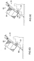
- the elevating unit 20 can be used to help manipulate a manual hand truck 22 and a payload 25 thereon up a flight of stairs, as can be best seen in Figures 6A through 6E.
- the elevating unit 20 is attached to the hand truck 22, in the manner described immediately above, and the elevating unit 20 and the hand truck 22 are wheeled to the bottom of the stairs 23, as is best seen in Figure 6A.
- the elevating unit 20 and the hand truck 22 are tilted rearwardly, as indicated by arrow "G" in Figure 6B.
- the electrical switch 82 is then manipulated to its first position so as to cause the reversible motor 82 to rotate the elongate threaded rod 71 in a first direction "F", thus causing the circulating ball nut 72 and the extension leg 60 to travel along the elongate threaded rod 71 in a first direction as indicated by arrow "C” of Figure 6C, toward the first extended position of the extension leg 60.
- the remainder of the elevating unit 20, the hand truck 22, and the payload 25 thereon are lifted upwardly, as indicated by arrow "H" in Figure 6C.
- the electrical switch 82 When the wheels 46 of the hand truck 22 are slightly above a selected step of the stairs 23, the electrical switch 82 is manipulated to its third (neutral) position so as to stop the reversible motor 80.
- the elevating unit 20 and the hand truck 22 and payload 25 thereon are then leaned toward the stairs 23 until the wheels 46 are resting on said selected one of the steps of the stairs 23, as shown in Figure 6D.
- the electrical switch 82 is then manipulated to its second position so as to cause the reversible motor 80 to rotate the elongate threaded rod in its second rotational direction "S", thus causing the extension leg 60 to move in a second direction as indicated by arrow "D" in Figure 6E, towards its second retracted position.
- the same cycle of steps is then repeated to move the hand truck 22 and payload 25 up subsequent ones of the steps 23.
- the elevating unit 20 may be used to also manipulate a manual hand truck 22 and a payload 25 thereon down a set of stairs, by using a generally reversed procedure to that described above.
- the elevating unit 20 may be used to assist in lifting the hand truck 22 and payload 25 thereon onto the delivery truck 21, as shown by arrow "J" in Figure 7B, in a manner similar to that described for manipulating the hand truck 22 and payload 25 thereon up a flight of stairs.
- the elevating unit 20 may be used to also manipulate a manual hand truck 22 and a payload thereon down off of the delivery truck 21.
- a very important advantage of the elevating unit 20 of the present invention over the prior art is that of cost efficiency. It is not necessary to replace presently owned manual hand trucks, many of which manual hand trucks are quite expensive, with even more expensive powered hand trucks. Instead, it is necessary to purchase a desired quantity of the relatively inexpensive elevating unit of the present invention only as complementary units to presently owned manual hand trucks.
Landscapes
- Engineering & Computer Science (AREA)
- Chemical & Material Sciences (AREA)
- Combustion & Propulsion (AREA)
- Transportation (AREA)
- Mechanical Engineering (AREA)
- Handcart (AREA)
- Manipulator (AREA)
- Prostheses (AREA)
- Forklifts And Lifting Vehicles (AREA)
Claims (17)
- Kombination aus einer Handkarre und einer Hebeeinheit, bei der:die Handkarre folgendes hat: einen Rahmen, der in einer im wesentlichen senkrechten Richtung von einem unteren Ende zu einem oberen Ende reicht und der seitlich von einer linken Seite zu einer rechten Seite reicht, wobei sich im wesentlichen zwischen der linken und der rechten Seite des Rahmens obere und untere Querelemente erstrecken, Handgriffmittel, die anschließend an das obere Ende angeordnet sind, eine Vorderseite und eine Rückseite, wobei sich eine Nutzlast-Auflagefläche von der Vorderseite nach vorn erstreckt, und ein Paar Räder, die im Anschluß an das untere Ende des Rahmens zur Drehung um eine gemeinsame Querachse funktionell an diesem angebracht sind; bei derdie Hebeeinheit folgendes hat: einen Hauptabschnitt mit einer Vorderseite und einer Rückseite, einen Ausfahrabschnitt, der einen Fußabschnitt hat und für die selektiv gesteuerte Bewegung zwischen einer ersten, ausgezogenen Position, in der sich der Fußabschnitt unter dem unteren Ende des Rahmens befindet, und einer zweiten, zusammengeschobenen Position, in welcher der Fußabschnitt gegenüber der Anordnung unter dem unteren Ende des Rahmens angehoben ist, funktionell an dem Hauptabschnitt befestigt ist, Antriebsmittel, die funktionell mit dem Ausfahrabschnitt gekoppelt sind, um den Ausfahrabschnitt selektiv in einer ersten Richtung aus der ersten, ausgezogenen Position in die zweite, zusammengeschobene Position und in einer zweiten Richtung aus der zweiten, zusammengeschobenen Position in die erste, ausgezogene Position zu bewegen, Steuerungsmittel, die funktionell mit den Antriebsmitteln gekoppelt sind, um die selektive Betätigung der Antriebsmittel in der ersten und zweiten Richtung zu ermöglichen; und bei der die Verbesserung in folgendem besteht:ersten Haltemitteln, die für einen leicht lösbaren Sicherungseingriff des Hauptabschnitts mit dem oberen Querelement der Handkarre an dem Hauptabschnitt in einem Dispositionsverhältnis zur Vorderseite des Hauptabschnitts angebracht sind, wobei die ersten Haltemittel im Querschnitt im wesentlichen eine C-Form haben, die eine nach vom zeigende Öffnung definiert, wobei ein unterer Arm der C-Form einen lasttragenden Abschnitt bildet und ein oberer Arm der C-Form einen gewichtübertragenden Abschnitt bildet, um einen Teil des Gewichts der Hebeeinheit auf das obere Querelement zu übertragen, wobei der obere und untere Armabschnitt mit einem ausreichenden Zwischenraum zueinander angeordnet sind, um zwischen sich das obere Querelement aufzunehmen;Öffnungblockiermittel, die leicht zwischen einer ersten, einer Blockierposition, in der die Öffnungblockiermittel die Öffnung verschließen, um dadurch das obere Querelement in einem einsatzbereiten, gesicherten Verhältnis zu halten, und einer zweiten, offenen Position bewegt werden können, in der die Öffnungblockiermittel aus der Verschlußposition der Öffnung entfernt worden sind, um dadurch das Hinein- und Herausführen des oberen Querelements zu ermöglichen; undzweite Haltemittel, die für einen leicht lösbaren Sicherungseingriff des Hauptabschnitts mit dem unteren Querelement starr an dem Hauptabschnitt angebracht sind und ein Dispositionsverhältnis zu der Rückseite des Hauptabschnitts aufweisen, wobei die zweiten Haltemittel einen gewichtübertragenden Abschnitt aufweisen, der so geformt und bemessen ist, daß er in einem Gewichtübertragungsverhältnis auf dem unteren Querelement ruht, um einen Teil des Gewichts der Hebeeinheit auf das untere Querelement zu übertragen.
- Kombination nach Anspruch 1, bei der die Hebeeinheit außerdem einen Flanschabschnitt aufweist, der von dem gewichtübertragenden Abschnitt der zweiten Haltemittel abhängig ist, derartig, daß der Flanschabschnitt, der gewichtübertragende Abschnitt und der Hauptabschnitt zusammen ein nach unten offenes, allgemein U-förmiges Profil bilden, das so bemessen ist, daß darin das untere Querelement aufgenommen werden kann.
- Kombination nach Anspruch 2, bei der das untere Querelement der Handkarre ein Achsenelement aufweist, das die gemeinsame Querachse bildet.
- Kombination nach Anspruch 3, bei der die Handkarre außerdem ein Paar Abstandshalter aufweist, die in einem umschließenden Verhältnis um das Achsenelement angeordnet sind, wobei die Abstandshalter auf dem Achsenelement durch eine in der Mitte angeordnete Lücke mit Zwischenraum zueinander angeordnet sind, und bei der die zweiten Haltemittel an der Lücke mit dem Achsenelement ineinandergreifen.
- Kombination nach Anspruch 4, bei welcher der Ausfahrabschnitt langgestreckt längs einer ersten Längsachse ist.
- Kombination nach Anspruch 5, bei welcher der Ausfahrabschnitt im wesentlichen senkrecht angeordnet ist, wenn er sich in der ersten, ausgezogenen Position befindet.
- Kombination nach Anspruch 6, bei welcher der Ausfahrabschnitt im wesentlichen senkrecht angeordnet ist, wenn er sich in der zweiten, zusammengeschobenen Position befindet.
- Kombination nach Anspruch 7, bei der sich der Ausfahrabschnitt linear längs seiner ersten Längsachse bewegt, wenn er sich zwischen seiner ersten, ausgezogenen Position und seiner zweiten, zusammengeschobenen Position bewegt.
- Kombination nach Anspruch 8, bei der die Antriebsmittel folgendes umfassen: eine im wesentlichen senkrecht angeordnete, längliche Gewindestange, die eine zweite Längsachse hat, die im wesentlichen axial mit der ersten Längsachse ausgerichtet ist und die zur Drehung in entgegengesetzten ersten und zweiten Rotationsrichtungen um die zweite Längsachse funktionell an dem Hauptabschnitt angebracht ist, eine Kugelumlaufinutter, die sich schraubend auf der länglichen Gewindestange im Eingriff befindet, um sich über deren Länge zu bewegen, wenn sich die längliche Gewindestange dreht, und bei welcher der Ausfahrabschnitt an der Kugelumlaufmutter befestigt ist, um sich wie oben mit dieser zu bewegen, wobei die Drehung der Gewindestange in der ersten Rotationsrichtung die lineare Bewegung des Ausfahrabschnitts in die erste, ausgezogene Position bewirkt und die Drehung der Gewindestange in der zweiten Rotationsrichtung die lineare Bewegung des Ausfahrabschnitts in die zweite, zusammengeschobene Position bewirkt.
- Kombination nach Anspruch 9, bei welcher der Ausfahrabschnitt in einem Gleitverhältnis innerhalb des Hauptabschnitts und in einem umschließenden Verhältnis zu der Gewindestange angeordnet ist.
- Kombination nach Anspruch 10, die außerdem Gleitlagermittel aufweist, die in einem funktionellen Verhältnis zwischen dem Ausfahrabschnitt und dem Hauptabschnitt angeordnet sind.
- Kombination nach Anspruch 11, bei der die Gleitlagermittel eine erste Lagerbaugruppe, die angrenzend an das obere Ende des Ausfahrabschnitts an diesem angebracht ist, und eine zweite Lagerbaugruppe aufweist, die angrenzend an das obere Ende des Hauptabschnitts an diesem angebracht ist.
- Kombination nach Anspruch 12, bei der die Antriebsmittel Motormittel umfassen, die funktionell mit der länglichen Gewindestange verbunden sind, um die längliche Gewindestange in den entgegengesetzten ersten und zweiten Rotationsrichtungen zu drehen.
- Kombination nach Anspruch 13, bei der die Motormittel einen elektrisch zu speisenden Umkehrmotor umfassen.
- Kombination nach Anspruch 14, bei der die Steuerungsmittel einen elektrischen Dreiwegschalter aufweisen, der in einem elektrisch leitenden Verhältnis zwischen einer Elektroenergiequelle und dem elektrisch zu speisenden Motor geschaltet ist, wobei eine erste Position des elektrischen Dreiwegschalters die Rotation der Gewindestange in der ersten Rotationsrichtung bewirkt, eine zweite Position des elektrischen Dreiwegschalters die Rotation der Gewindestange in der zweiten Rotationsrichtung bewirkt und eine dritte Position des elektrischen Dreiwegschalters die Rotation der Gewindestange ausschließt.
- Kombination nach Anspruch 15, bei der die Elektroenergiequelle eine elektrische Speicherzelle umfaßt, die an dem Hauptabschnitt angebracht ist.
- Kombination nach Anspruch 16, bei der die elektrische Speicherstelle vor Ort aufgeladen werden kann.
Applications Claiming Priority (1)
| Application Number | Priority Date | Filing Date | Title |
|---|---|---|---|
| PCT/CA1996/000670 WO1998015448A1 (en) | 1996-10-09 | 1996-10-09 | Elevating unit for a hand truck |
Publications (2)
| Publication Number | Publication Date |
|---|---|
| EP0929435A1 EP0929435A1 (de) | 1999-07-21 |
| EP0929435B1 true EP0929435B1 (de) | 2000-06-28 |
Family
ID=4173175
Family Applications (1)
| Application Number | Title | Priority Date | Filing Date |
|---|---|---|---|
| EP96932406A Expired - Lifetime EP0929435B1 (de) | 1996-10-09 | 1996-10-09 | Hebe-vorrichtung für eine handkarre |
Country Status (7)
| Country | Link |
|---|---|
| EP (1) | EP0929435B1 (de) |
| JP (1) | JP2001501555A (de) |
| AT (1) | ATE194108T1 (de) |
| AU (1) | AU7123096A (de) |
| CA (1) | CA2266894A1 (de) |
| DE (1) | DE69609088T2 (de) |
| WO (1) | WO1998015448A1 (de) |
Family Cites Families (3)
| Publication number | Priority date | Publication date | Assignee | Title |
|---|---|---|---|---|
| US2608258A (en) * | 1948-04-19 | 1952-08-26 | Frederick T Jenkins | Power hand truck |
| US3893679A (en) * | 1973-05-14 | 1975-07-08 | Howell M Sumrall | Hand truck step climber |
| SE500173C2 (sv) * | 1992-03-12 | 1994-05-02 | Arronet Teknik Ab | Trappgående mekanism |
-
1996
- 1996-10-09 EP EP96932406A patent/EP0929435B1/de not_active Expired - Lifetime
- 1996-10-09 AU AU71230/96A patent/AU7123096A/en not_active Abandoned
- 1996-10-09 AT AT96932406T patent/ATE194108T1/de not_active IP Right Cessation
- 1996-10-09 JP JP10517029A patent/JP2001501555A/ja not_active Ceased
- 1996-10-09 CA CA002266894A patent/CA2266894A1/en not_active Abandoned
- 1996-10-09 DE DE69609088T patent/DE69609088T2/de not_active Expired - Fee Related
- 1996-10-09 WO PCT/CA1996/000670 patent/WO1998015448A1/en not_active Ceased
Also Published As
| Publication number | Publication date |
|---|---|
| AU7123096A (en) | 1998-05-05 |
| JP2001501555A (ja) | 2001-02-06 |
| EP0929435A1 (de) | 1999-07-21 |
| ATE194108T1 (de) | 2000-07-15 |
| DE69609088D1 (de) | 2000-08-03 |
| WO1998015448A1 (en) | 1998-04-16 |
| DE69609088T2 (de) | 2001-03-08 |
| CA2266894A1 (en) | 1998-04-16 |
Similar Documents
| Publication | Publication Date | Title |
|---|---|---|
| US6309168B1 (en) | Lift for a hand truck | |
| US5573078A (en) | Steerable, self-powered shopping cart towing apparatus and method for making same | |
| CA1264308A (en) | Powered lifter | |
| US3876024A (en) | Motorized vehicle for moving hospital beds and the like | |
| EP1012104B1 (de) | Fahrzeug zum personentransport | |
| CA1069088A (en) | Power control hand truck | |
| US5829763A (en) | Power assisted lifting device | |
| US6241047B1 (en) | Personnel carrying vehicle | |
| US5992572A (en) | Personnel carrying vehicle | |
| US6938711B2 (en) | Freestanding self-propelled device for moving objects | |
| US6398477B1 (en) | Electric hand truck | |
| US4287966A (en) | Industrial truck | |
| US20110206489A1 (en) | Load transport system and method | |
| US4034878A (en) | Electric hand trucks | |
| GB1601930A (en) | Devices for driving mobile trolleys | |
| EP0241096A2 (de) | Mobile Hebevorrichtung zur Handhabung von Patienten | |
| JP2005528300A (ja) | 揚重移送装置 | |
| US7210590B2 (en) | Transportation cart primarily for use in an animal barn | |
| CA2463329C (en) | Transportation cart primarily for use in an animal barn | |
| CA2303253C (en) | Personnel carrying vehicle | |
| CN213651756U (zh) | 一种手推电动叉车 | |
| EP0765837B1 (de) | Bewegliche Hebevorrichtung | |
| EP0929435A1 (de) | Hebe-vorrichtung für eine handkarre | |
| US4620603A (en) | Articulated tow vehicle | |
| AU694019B2 (en) | Motorized towing vehicle |
Legal Events
| Date | Code | Title | Description |
|---|---|---|---|
| PUAI | Public reference made under article 153(3) epc to a published international application that has entered the european phase |
Free format text: ORIGINAL CODE: 0009012 |
|
| 17P | Request for examination filed |
Effective date: 19990323 |
|
| AK | Designated contracting states |
Kind code of ref document: A1 Designated state(s): AT BE CH DE DK ES FI FR GB GR IE IT LI LU MC NL PT SE |
|
| GRAG | Despatch of communication of intention to grant |
Free format text: ORIGINAL CODE: EPIDOS AGRA |
|
| 17Q | First examination report despatched |
Effective date: 19990806 |
|
| GRAG | Despatch of communication of intention to grant |
Free format text: ORIGINAL CODE: EPIDOS AGRA |
|
| GRAH | Despatch of communication of intention to grant a patent |
Free format text: ORIGINAL CODE: EPIDOS IGRA |
|
| GRAH | Despatch of communication of intention to grant a patent |
Free format text: ORIGINAL CODE: EPIDOS IGRA |
|
| GRAA | (expected) grant |
Free format text: ORIGINAL CODE: 0009210 |
|
| AK | Designated contracting states |
Kind code of ref document: B1 Designated state(s): AT BE CH DE DK ES FI FR GB GR IE IT LI LU MC NL PT SE |
|
| PG25 | Lapsed in a contracting state [announced via postgrant information from national office to epo] |
Ref country code: NL Free format text: LAPSE BECAUSE OF FAILURE TO SUBMIT A TRANSLATION OF THE DESCRIPTION OR TO PAY THE FEE WITHIN THE PRESCRIBED TIME-LIMIT Effective date: 20000628 Ref country code: LI Free format text: LAPSE BECAUSE OF FAILURE TO SUBMIT A TRANSLATION OF THE DESCRIPTION OR TO PAY THE FEE WITHIN THE PRESCRIBED TIME-LIMIT Effective date: 20000628 Ref country code: GR Free format text: LAPSE BECAUSE OF NON-PAYMENT OF DUE FEES Effective date: 20000628 Ref country code: FI Free format text: LAPSE BECAUSE OF FAILURE TO SUBMIT A TRANSLATION OF THE DESCRIPTION OR TO PAY THE FEE WITHIN THE PRESCRIBED TIME-LIMIT Effective date: 20000628 Ref country code: ES Free format text: THE PATENT HAS BEEN ANNULLED BY A DECISION OF A NATIONAL AUTHORITY Effective date: 20000628 Ref country code: CH Free format text: LAPSE BECAUSE OF FAILURE TO SUBMIT A TRANSLATION OF THE DESCRIPTION OR TO PAY THE FEE WITHIN THE PRESCRIBED TIME-LIMIT Effective date: 20000628 Ref country code: AT Free format text: LAPSE BECAUSE OF FAILURE TO SUBMIT A TRANSLATION OF THE DESCRIPTION OR TO PAY THE FEE WITHIN THE PRESCRIBED TIME-LIMIT Effective date: 20000628 |
|
| REF | Corresponds to: |
Ref document number: 194108 Country of ref document: AT Date of ref document: 20000715 Kind code of ref document: T |
|
| REG | Reference to a national code |
Ref country code: CH Ref legal event code: EP |
|
| REG | Reference to a national code |
Ref country code: IE Ref legal event code: FG4D |
|
| REF | Corresponds to: |
Ref document number: 69609088 Country of ref document: DE Date of ref document: 20000803 |
|
| ITF | It: translation for a ep patent filed | ||
| PG25 | Lapsed in a contracting state [announced via postgrant information from national office to epo] |
Ref country code: PT Free format text: LAPSE BECAUSE OF FAILURE TO SUBMIT A TRANSLATION OF THE DESCRIPTION OR TO PAY THE FEE WITHIN THE PRESCRIBED TIME-LIMIT Effective date: 20000928 Ref country code: DK Free format text: LAPSE BECAUSE OF FAILURE TO SUBMIT A TRANSLATION OF THE DESCRIPTION OR TO PAY THE FEE WITHIN THE PRESCRIBED TIME-LIMIT Effective date: 20000928 |
|
| ET | Fr: translation filed | ||
| PG25 | Lapsed in a contracting state [announced via postgrant information from national office to epo] |
Ref country code: LU Free format text: LAPSE BECAUSE OF NON-PAYMENT OF DUE FEES Effective date: 20001009 Ref country code: IE Free format text: LAPSE BECAUSE OF NON-PAYMENT OF DUE FEES Effective date: 20001009 |
|
| PG25 | Lapsed in a contracting state [announced via postgrant information from national office to epo] |
Ref country code: MC Free format text: THE PATENT HAS BEEN ANNULLED BY A DECISION OF A NATIONAL AUTHORITY Effective date: 20001031 |
|
| NLV1 | Nl: lapsed or annulled due to failure to fulfill the requirements of art. 29p and 29m of the patents act | ||
| REG | Reference to a national code |
Ref country code: CH Ref legal event code: PL |
|
| PLBE | No opposition filed within time limit |
Free format text: ORIGINAL CODE: 0009261 |
|
| STAA | Information on the status of an ep patent application or granted ep patent |
Free format text: STATUS: NO OPPOSITION FILED WITHIN TIME LIMIT |
|
| 26N | No opposition filed | ||
| REG | Reference to a national code |
Ref country code: IE Ref legal event code: MM4A |
|
| REG | Reference to a national code |
Ref country code: GB Ref legal event code: IF02 |
|
| PGFP | Annual fee paid to national office [announced via postgrant information from national office to epo] |
Ref country code: SE Payment date: 20021004 Year of fee payment: 7 |
|
| PGFP | Annual fee paid to national office [announced via postgrant information from national office to epo] |
Ref country code: BE Payment date: 20021220 Year of fee payment: 7 |
|
| PGFP | Annual fee paid to national office [announced via postgrant information from national office to epo] |
Ref country code: FR Payment date: 20031003 Year of fee payment: 8 |
|
| PGFP | Annual fee paid to national office [announced via postgrant information from national office to epo] |
Ref country code: GB Payment date: 20031008 Year of fee payment: 8 |
|
| PG25 | Lapsed in a contracting state [announced via postgrant information from national office to epo] |
Ref country code: SE Free format text: LAPSE BECAUSE OF NON-PAYMENT OF DUE FEES Effective date: 20031010 |
|
| PGFP | Annual fee paid to national office [announced via postgrant information from national office to epo] |
Ref country code: DE Payment date: 20031016 Year of fee payment: 8 |
|
| PG25 | Lapsed in a contracting state [announced via postgrant information from national office to epo] |
Ref country code: BE Free format text: LAPSE BECAUSE OF NON-PAYMENT OF DUE FEES Effective date: 20031031 |
|
| BERE | Be: lapsed |
Owner name: *JEAVONS PETER K. Effective date: 20031031 |
|
| EUG | Se: european patent has lapsed | ||
| PG25 | Lapsed in a contracting state [announced via postgrant information from national office to epo] |
Ref country code: GB Free format text: LAPSE BECAUSE OF NON-PAYMENT OF DUE FEES Effective date: 20041009 |
|
| PG25 | Lapsed in a contracting state [announced via postgrant information from national office to epo] |
Ref country code: DE Free format text: LAPSE BECAUSE OF NON-PAYMENT OF DUE FEES Effective date: 20050503 |
|
| GBPC | Gb: european patent ceased through non-payment of renewal fee |
Effective date: 20041009 |
|
| PG25 | Lapsed in a contracting state [announced via postgrant information from national office to epo] |
Ref country code: FR Free format text: LAPSE BECAUSE OF NON-PAYMENT OF DUE FEES Effective date: 20050630 |
|
| REG | Reference to a national code |
Ref country code: FR Ref legal event code: ST |
|
| PG25 | Lapsed in a contracting state [announced via postgrant information from national office to epo] |
Ref country code: IT Free format text: LAPSE BECAUSE OF NON-PAYMENT OF DUE FEES Effective date: 20051009 |