EP0929478B1 - Behälter zur aufnahme von spänen - Google Patents
Behälter zur aufnahme von spänen Download PDFInfo
- Publication number
- EP0929478B1 EP0929478B1 EP97932083A EP97932083A EP0929478B1 EP 0929478 B1 EP0929478 B1 EP 0929478B1 EP 97932083 A EP97932083 A EP 97932083A EP 97932083 A EP97932083 A EP 97932083A EP 0929478 B1 EP0929478 B1 EP 0929478B1
- Authority
- EP
- European Patent Office
- Prior art keywords
- chip bin
- section
- discharge
- bin according
- relation
- Prior art date
- Legal status (The legal status is an assumption and is not a legal conclusion. Google has not performed a legal analysis and makes no representation as to the accuracy of the status listed.)
- Expired - Lifetime
Links
- 230000003247 decreasing effect Effects 0.000 claims abstract description 5
- 230000001154 acute effect Effects 0.000 claims abstract description 4
- 230000007423 decrease Effects 0.000 claims description 4
- 230000015572 biosynthetic process Effects 0.000 description 4
- 239000000463 material Substances 0.000 description 4
- 238000010025 steaming Methods 0.000 description 4
- 238000010276 construction Methods 0.000 description 3
- 239000002184 metal Substances 0.000 description 2
- 239000002131 composite material Substances 0.000 description 1
- 238000007599 discharging Methods 0.000 description 1
- 239000008187 granular material Substances 0.000 description 1
- 238000012423 maintenance Methods 0.000 description 1
- 239000008188 pellet Substances 0.000 description 1
- 230000002787 reinforcement Effects 0.000 description 1
Images


Classifications
-
- B—PERFORMING OPERATIONS; TRANSPORTING
- B65—CONVEYING; PACKING; STORING; HANDLING THIN OR FILAMENTARY MATERIAL
- B65D—CONTAINERS FOR STORAGE OR TRANSPORT OF ARTICLES OR MATERIALS, e.g. BAGS, BARRELS, BOTTLES, BOXES, CANS, CARTONS, CRATES, DRUMS, JARS, TANKS, HOPPERS, FORWARDING CONTAINERS; ACCESSORIES, CLOSURES, OR FITTINGS THEREFOR; PACKAGING ELEMENTS; PACKAGES
- B65D88/00—Large containers
- B65D88/26—Hoppers, i.e. containers having funnel-shaped discharge sections
- B65D88/28—Construction or shape of discharge section
-
- Y—GENERAL TAGGING OF NEW TECHNOLOGICAL DEVELOPMENTS; GENERAL TAGGING OF CROSS-SECTIONAL TECHNOLOGIES SPANNING OVER SEVERAL SECTIONS OF THE IPC; TECHNICAL SUBJECTS COVERED BY FORMER USPC CROSS-REFERENCE ART COLLECTIONS [XRACs] AND DIGESTS
- Y10—TECHNICAL SUBJECTS COVERED BY FORMER USPC
- Y10S—TECHNICAL SUBJECTS COVERED BY FORMER USPC CROSS-REFERENCE ART COLLECTIONS [XRACs] AND DIGESTS
- Y10S220/00—Receptacles
- Y10S220/13—Odd-shaped
Definitions
- the present invention relates to a chip bin which is used within the pulp industry and is used for storing and possibly steaming chips for producing pulp.
- chip bins includes some form of tubular outlet device in order to ensure continuous discharge, such as for example the frequently used so-called "Vibra Bin".
- Vibra Bin the frequently used so-called "Vibra Bin”.
- a disadvantage of such chip bins is that they are relatively expensive to maintain, among other things because of wear and the necessary maintenance associated therewith.
- a chip bin which works entirely without moving parts is previously known through US 4,958,741. If the climate allows, such a chip bin can function satisfactorily. The principle is based on the cross-section of the chip bin being reduced in stages down towards the discharge opening in a manner which eliminates the risk of bridge formation and consequently, with certain climatic prerequisites, continuous discharge can be ensured with such a construction.
- the known device is based on the alternating use of oval and circular cross-sections. Such a construction leads to a disadvantage in that the oval cross-section is not optimal as far as strength is concerned. Furthermore, it is relatively complicated to construct and is therefore expensive.
- the aim of the present invention is to produce a chip bin which is based on a principle of functioning without moving parts but at the same time eliminates the abovementioned disadvantages of the known embodiment.
- the solution is based on a chip bin comprising a feeding device, an upper container part, a discharge opening and, arranged between the container part and the discharge opening, a discharge zone, without moving parts, the discharge zone having a circular shape in any freely chosen horizontal cross-section, and on the fact that the cross-section of the discharge zone decreases from the container part (4) down towards the discharge opening (7), at least one section (3) of said discharge zone essentially having the shape of a truncated cone with a downwardly continuously decreasing circular cross-section, the centre point of which is continuously moved in relation to a vertical line, which is fixed with regard to the chip bin, in such a manner that said section (3) has a centre line which forms an acute angle ( ⁇ ) in relation to the vertical line.
- Figure 1 shows a diagrammatic side view of a chip bin according to the invention
- Figure 2 shows the same embodiment in a view from above
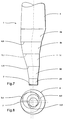
- Figure 3 shows a preferred embodiment of a chip bin in a side view
- Figure 4 shows the same preferred embodiment in a view from above
- Figures 5 and 6 show a chip bin which is somewhat modified in relation to the preferred embodiment
- Figures 7 and 8 show an alternative positioning of the sections in the outlet arrangement of a chip bin according to the invention.
- Figure 1 shows a side view of a chip bin (1) with a discharge zone (2, 3, 7) according to the invention.
- the discharge zone comprises a number of circular units (2a, 2b, 2c, 2d).
- the largest circular unit (2a) is located uppermost in the discharge part of the chip bin and the smallest circular unit (2d) is located at the bottom and thus itself also forms the discharge opening (7) from the chip bin (1).
- two further circular units (2b) and (2c) are located, the diameter of which decreases gradually in relation to the largest, upper unit (2a).
- Each circular unit is positioned in a non-centred manner in relation to the circular unit immediately above or below, see Figure 2.
- each circular unit (2) there is a connecting element which essentially has the shape of a truncated cone (3), the horizontal cross-section of which is circular in any chosen section.
- a container part (4) is situated, the design of which may vary but which expediently has a circular cross-section and is upwardly slightly conical so that a certain clearance is obtained along the inner periphery.
- a feeding device (5) (not described further) is arranged, which normally consists of a pipe which is fed via a belt or screw conveyor (not shown).
- the outlet opening (7) is connected to a steaming vessel (6) which is shown only diagrammatically in the figure.
- a chip meter (6') known per se is arranged between the steaming vessel (6) and the outlet opening.
- the bin functions in such a manner that chips are fed in at the top and flow into the bin at the top through the feeding device (5).
- the feed flow is controlled in relation to the discharge flow and the quantity of chips present in the bin in such a manner that the desired chip level is obtained in the bin (1).
- Discharge of chips from the bin takes place entirely according to the principle of unassisted falling.
- the chips can fall out of their own accord without bridge formation because the outlet opening (2d) has a height (h) which is sufficiently small, in relation to the diameter (d), to eliminate the occurrence of bridge formation, preferably smaller than 1.5 d and most preferably smaller than d.
- FIGS 3 and 4 show a preferred embodiment of a chip bin according to the invention.
- 4 sections (3a, 3b, 3c, 3d) are arranged, which essentially have the shape of a truncated cone.
- Each such section has in any freely chosen horizontal cross-section a circular shape which continuously decreases in the downward direction towards the outlet opening (7).
- Each conical section (3) is positioned in such a manner that it has a downwardly continuously decreasing circular cross-section, the centre point of which is continuously moved in relation to a vertical line, which is fixed with regard to the chip bin, so that its centre line which forms an acute angle ( ⁇ ) with the vertical line.
- each such section (3) is positioned in such a manner that one (8) of its wall parts is located on the vertical line.
- the length (1) of the centre line of each section (3) is such that it is shorter than the maximum diameter of the section which means, for the next to uppermost section (3b), that 1 is smaller than the diameter at the joint ab between this section and the similar section (3a) situated above it.
- Figure 4 shows, with the aid of a view from above, how the various sections (2d, 3a, 3b, 3c, 3d, 4) are positioned in relation to one another, the line of symmetry for each section lying in one and the same vertical plane (9). The principle of functioning for this preferred embodiment is the same as for that described above.
- FIGs 5 and 6 show in principle the same kind of discharge zone as in Figures 3 and 4.
- the one difference is that each wall part (8) which is located essentially on the vertical line is arranged so that a small clearance angle ( ⁇ ) is obtained.
- Figures 7 and 8 show an alternative positioning of the sections in relation to one another, the wall part (8) which coincides with the vertical line being displaced by 90° with regard to the section lying above and below respectively.
- the horizontal cross-section in any chosen section is circular.
- a major advantage of the abovementioned embodiment is that the bin is made up of circular cross-sections, because the chip bin is exposed to great pressure from within. It is generally known that a circular shape is optimal as far as strength is concerned in connection with pressurization from within, because among other things the material thickness can then be made smaller than in any other shape which deviates from purely circular. Moreover, thanks to the circular shape, reinforcement arrangements can be dispensed with entirely. Additionally, the circular shape results in computer processing becoming easier, which results in simpler, more rational construction work and sheet-metal preparation etc. It is therefore obvious that the preferred embodiment according to the invention has clear advantages in comparison with using oval cross-sections or other non-circular cross-sections such as for example hexagonal cross-sections.
- the choice of material can of course be adapted to specific requirements and made for example of composite material, but the most preferred material is sheet metal. It is furthermore understood that the invention can also be used for discharging material other than chips, for example pellets or granulate.
Landscapes
- Engineering & Computer Science (AREA)
- Mechanical Engineering (AREA)
- Filling Or Emptying Of Bunkers, Hoppers, And Tanks (AREA)
- Closures For Containers (AREA)
- Packaging Frangible Articles (AREA)
- Confectionery (AREA)
- Control And Other Processes For Unpacking Of Materials (AREA)
- Crystals, And After-Treatments Of Crystals (AREA)
Claims (12)
- Schnitzelsilo mit einer Speisevorrichtung (5), einem oberen "Behälterteil (4), dessen Durchmesser größer als 2,5 m, vorzugsweise 3,5 m und besonders bevorzugt 4,5 m ist, einer Austragsöffnung (7), deren Durchmesser kleiner als 2,5 m ist, und ein zwischen dem oberen Behälterteil (4) und der Austragsöffnung (7) angeordneter Austragsbereich (2, 3) ohne sich bewegende Teile, wobei der Austragsbereich (2, 3) in jedem frei gewählten horizontalen Querschnitt eine kreisrunde Form aufweist und der Querschnitt des Austragsbereichs (2, 3) vom Behälterteil (4) nach unten zur Austragsöffnung (7) abnimmt, wobei mindestens zwei Abschnitte (3) des Austragsbereichs im wesentlichen die Form eines Kegelstumpfes mit einem nach unten kontinuierlich abnehmenden kreisrunden Querschnitt aufweisen, dessen Mittelpunkt bezüglich einer Vertikallinie, die bezüglich des Schnitzelsilos feststehend ist, kontinuierlich derart bewegt wird, daß die Abschnitte (3) eine Mittellinie aufweisen, die zur Vertikallinie einen spitzen Winkel (α) bildet, und jeder kreisförmige Abschnitt bezüglich eines unmittelbar darüber oder darunter angeordneten kreisförmigen Abschnitts unzentriert positioniert ist.
- Schnitzelsilo nach Anspruch 1, dadurch gekennzeichnet, daß der Austragsbereich mindestens zwei, vorzugsweise mindestens drei und besonders bevorzugt mindestens vier der Abschnitte (3) umfaßt.
- Schnitzelsilo nach Anspruch 1, dadurch gekennzeichnet, daß der Austragsabschnitt des weiteren mindestens zwei zylindrische Einheiten (2) unterschiedlicher Größe umfaßt und daß jede zylindrische Einheit bezüglich der unmittelbar darüber liegenden zylindrischen Einheit unzentriert positioniert ist.
- Schnitzelsilo nach Anspruch 3, dadurch gekennzeichnet, daß jede zylindrische Einheit (2) bezüglich jeder anderen zylindrischen Einheit mit Ausnahme des Behälterteils (4) selbst unzentriert positioniert ist.
- Schnitzelsilo nach Anspruch 3, dadurch gekennzeichnet, daß der Teil des Austragsabschnitts (3), der jede der benachbarten zylindrischen Einheiten (2) verbindet, im wesentlichen kegelstumpfförmig ist.
- Schnitzelsilo nach einem der vorhergehenden Ansprüche, dadurch gekennzeichnet, daß ein Wandteil (8) des Kegelstumpfes (3) im wesentlichen auf der Vertikallinie angeordnet ist.
- Schnitzelsilo nach Anspruch 1, dadurch gekennzeichnet, daß die Austragsöffnung (7) einen Durchmesser aufweist, der kleiner als 2 m, vorzugsweise kleiner als 1,5 m und besonders bevorzugt ca. 1 m ist.
- Schnitzelsilo nach Anspruch 3, dadurch gekennzeichnet, daß mindestens eine der zylindrischen Einheiten (2) nach oben leicht konvergiert, so daß ein Freiraum entsteht, wobei der Winkel zur Vertikallinie kleiner als 10°, vorzugsweise kleiner als 5° und besonders bevorzugt kleiner als 3° ist.
- Schnitzelsilo nach Anspruch 3, dadurch gekennzeichnet, daß mindestens eine der zylindrischen Einheiten vollkommen zylindrisch ist.
- Schnitzelsilo nach Anspruch 3, dadurch gekennzeichnet, daß die Höhe (h) der zylindrischen Einheiten kleiner als 2 d, vorzugsweise 1,5 d und besonders bevorzugt 1 d beträgt, wobei d den Durchmesser definiert.
- Schnitzelsilo nach Anspruch 1, dadurch gekennzeichnet, daß die Länge (1) der Mittellinie innerhalb des im wesentlichen kegelstumpfförmigen Abschnitts (3) kleiner als 2 max. d, vorzugsweise 1,5 max. d und besonders bevorzugt 1 max. d ist, wobei max. d den Durchmesser am größten kreisrunden Querschnitt des Kegels definiert.
- Schnitzelsilo nach Anspruch 8, dadurch gekennzeichnet, daß ein Wandteil (8) der zylindrischen Einheiten etwas von der Vertikallinie abweicht, so daß ein Freiraumwinkel (β) gebildet wird, der einen Winkel von 5° nicht überschreitet.
Applications Claiming Priority (3)
| Application Number | Priority Date | Filing Date | Title |
|---|---|---|---|
| SE9602709 | 1996-07-09 | ||
| SE9602709A SE505498C2 (sv) | 1996-07-09 | 1996-07-09 | Flisficka |
| PCT/SE1997/001146 WO1998001371A1 (en) | 1996-07-09 | 1997-06-26 | Chip bin |
Publications (2)
| Publication Number | Publication Date |
|---|---|
| EP0929478A1 EP0929478A1 (de) | 1999-07-21 |
| EP0929478B1 true EP0929478B1 (de) | 2001-12-12 |
Family
ID=20403333
Family Applications (1)
| Application Number | Title | Priority Date | Filing Date |
|---|---|---|---|
| EP97932083A Expired - Lifetime EP0929478B1 (de) | 1996-07-09 | 1997-06-26 | Behälter zur aufnahme von spänen |
Country Status (7)
| Country | Link |
|---|---|
| US (1) | US6029838A (de) |
| EP (1) | EP0929478B1 (de) |
| AT (1) | ATE210584T1 (de) |
| CA (1) | CA2258207A1 (de) |
| DE (1) | DE69709138D1 (de) |
| SE (1) | SE505498C2 (de) |
| WO (1) | WO1998001371A1 (de) |
Families Citing this family (6)
| Publication number | Priority date | Publication date | Assignee | Title |
|---|---|---|---|---|
| SE9803443D0 (sv) * | 1998-10-09 | 1998-10-09 | Kvaerner Pulping Tech | Chip bin |
| DE60102677T2 (de) * | 2001-05-31 | 2005-03-24 | Hylsa S.A. De C.V., San Nicolas De Los Garza | Gefäss zum Ermöglichen von gleichmassigem Schwerkraftabfluss von Schüttgut und Direktreduktionsreaktor derselben enthaltend |
| US6871457B2 (en) * | 2001-05-31 | 2005-03-29 | Hylsa, S.A. De C.V. | Vessel for enabling a uniform gravity driven flow of particulate bulk material therethrough, and direct reduction reactor incorporating same |
| US6609638B1 (en) | 2002-07-22 | 2003-08-26 | W. Gerald Lott | Flow promoter for hoppers |
| US8056343B2 (en) * | 2008-10-01 | 2011-11-15 | General Electric Company | Off center combustor liner |
| CN102390631A (zh) * | 2011-07-26 | 2012-03-28 | 中国神华能源股份有限公司 | 筒仓的出料漏斗和筒仓 |
Family Cites Families (6)
| Publication number | Priority date | Publication date | Assignee | Title |
|---|---|---|---|---|
| US1331372A (en) * | 1920-02-17 | Can or container | ||
| SE324231B (de) * | 1968-04-09 | 1970-05-25 | Rigello Pak Ab | |
| DE2029046C3 (de) * | 1970-06-12 | 1980-11-06 | Langen, Peter, 5030 Hermuelheim | Auslaufkasten für Schüttgutbunker |
| BE838769R (fr) * | 1975-07-08 | 1976-06-16 | Recipient metallique a parois de forte epaisseur | |
| US4452381A (en) * | 1982-03-29 | 1984-06-05 | Continental Plastics Company | Beverage dispensing system |
| US4958741A (en) * | 1989-06-14 | 1990-09-25 | Jr Johanson, Inc. | Modular mass-flow bin |
-
1996
- 1996-07-09 SE SE9602709A patent/SE505498C2/sv not_active IP Right Cessation
-
1997
- 1997-06-26 DE DE69709138T patent/DE69709138D1/de not_active Expired - Lifetime
- 1997-06-26 US US09/214,793 patent/US6029838A/en not_active Expired - Lifetime
- 1997-06-26 CA CA002258207A patent/CA2258207A1/en not_active Abandoned
- 1997-06-26 EP EP97932083A patent/EP0929478B1/de not_active Expired - Lifetime
- 1997-06-26 WO PCT/SE1997/001146 patent/WO1998001371A1/en not_active Ceased
- 1997-06-26 AT AT97932083T patent/ATE210584T1/de active
Also Published As
| Publication number | Publication date |
|---|---|
| EP0929478A1 (de) | 1999-07-21 |
| CA2258207A1 (en) | 1998-01-15 |
| SE9602709D0 (sv) | 1996-07-09 |
| SE9602709L (sv) | 1997-09-08 |
| DE69709138D1 (de) | 2002-01-24 |
| SE505498C2 (sv) | 1997-09-08 |
| ATE210584T1 (de) | 2001-12-15 |
| US6029838A (en) | 2000-02-29 |
| WO1998001371A1 (en) | 1998-01-15 |
Similar Documents
| Publication | Publication Date | Title |
|---|---|---|
| EP0937010A1 (de) | Verhinderung von brückenbildung in schüttgutbehältern | |
| US3985244A (en) | Silo, or bin, for flowable solid material | |
| US6871457B2 (en) | Vessel for enabling a uniform gravity driven flow of particulate bulk material therethrough, and direct reduction reactor incorporating same | |
| US6029838A (en) | Chip bin | |
| US5676827A (en) | Apparatus for discharge of sediment from a tank | |
| US6609638B1 (en) | Flow promoter for hoppers | |
| US3976232A (en) | Device for emptying silos for bulk material, provided with a flat or slightly inclined bottom | |
| US5083651A (en) | Tablet feed assembly | |
| WO1995009787A1 (en) | Conical inserts for chip bin | |
| EP1127019B1 (de) | Hackschnitzelsilo | |
| US4859067A (en) | Bulk material mixer | |
| US3710959A (en) | Silo container | |
| US3305276A (en) | Silo construction | |
| US6041914A (en) | Vibratory bowl for fragile parts | |
| US20040050770A1 (en) | Device for separating a substance into two phases | |
| EP0899347B1 (de) | Stempelkopf für eine Krätzepresse | |
| US4551242A (en) | Apparatus for dynamic classification of suspensions of solid bodies in liquids | |
| CA2322766C (en) | Arrangements in a barge for breeding purposes | |
| GB2125310A (en) | Dehydrating sieve apparatus | |
| CN209810445U (zh) | 一种多锥同心双溢流管三产品重介质旋流器 | |
| EP1264784B1 (de) | Gefäss zum Ermöglichen von gleichmassigem Schwerkraftabfluss von Schüttgut und Direktreduktionsreaktor derselben enthaltend | |
| EP1622820B1 (de) | Hopper mit flusssteuerung/enhancer zur steuerung des schwerkraftflusses von granulärem material | |
| US4795266A (en) | Solids blender with cylindrical inserts | |
| US5240328A (en) | Apparatus for mixing powdered or coarse-grained bulk materials | |
| RU99116697A (ru) | Установка гидроклассификации зернистых материалов |
Legal Events
| Date | Code | Title | Description |
|---|---|---|---|
| PUAI | Public reference made under article 153(3) epc to a published international application that has entered the european phase |
Free format text: ORIGINAL CODE: 0009012 |
|
| 17P | Request for examination filed |
Effective date: 19981223 |
|
| AK | Designated contracting states |
Kind code of ref document: A1 Designated state(s): AT DE ES FI FR PT |
|
| 17Q | First examination report despatched |
Effective date: 20001205 |
|
| GRAG | Despatch of communication of intention to grant |
Free format text: ORIGINAL CODE: EPIDOS AGRA |
|
| GRAG | Despatch of communication of intention to grant |
Free format text: ORIGINAL CODE: EPIDOS AGRA |
|
| GRAH | Despatch of communication of intention to grant a patent |
Free format text: ORIGINAL CODE: EPIDOS IGRA |
|
| GRAH | Despatch of communication of intention to grant a patent |
Free format text: ORIGINAL CODE: EPIDOS IGRA |
|
| GRAA | (expected) grant |
Free format text: ORIGINAL CODE: 0009210 |
|
| AK | Designated contracting states |
Kind code of ref document: B1 Designated state(s): AT DE ES FI FR PT |
|
| PG25 | Lapsed in a contracting state [announced via postgrant information from national office to epo] |
Ref country code: FR Free format text: LAPSE BECAUSE OF FAILURE TO SUBMIT A TRANSLATION OF THE DESCRIPTION OR TO PAY THE FEE WITHIN THE PRESCRIBED TIME-LIMIT Effective date: 20011212 Ref country code: FI Free format text: LAPSE BECAUSE OF FAILURE TO SUBMIT A TRANSLATION OF THE DESCRIPTION OR TO PAY THE FEE WITHIN THE PRESCRIBED TIME-LIMIT Effective date: 20011212 Ref country code: AT Free format text: LAPSE BECAUSE OF FAILURE TO SUBMIT A TRANSLATION OF THE DESCRIPTION OR TO PAY THE FEE WITHIN THE PRESCRIBED TIME-LIMIT Effective date: 20011212 |
|
| REF | Corresponds to: |
Ref document number: 210584 Country of ref document: AT Date of ref document: 20011215 Kind code of ref document: T |
|
| REF | Corresponds to: |
Ref document number: 69709138 Country of ref document: DE Date of ref document: 20020124 |
|
| PG25 | Lapsed in a contracting state [announced via postgrant information from national office to epo] |
Ref country code: PT Free format text: LAPSE BECAUSE OF FAILURE TO SUBMIT A TRANSLATION OF THE DESCRIPTION OR TO PAY THE FEE WITHIN THE PRESCRIBED TIME-LIMIT Effective date: 20020312 |
|
| PG25 | Lapsed in a contracting state [announced via postgrant information from national office to epo] |
Ref country code: DE Free format text: LAPSE BECAUSE OF FAILURE TO SUBMIT A TRANSLATION OF THE DESCRIPTION OR TO PAY THE FEE WITHIN THE PRESCRIBED TIME-LIMIT Effective date: 20020313 |
|
| PG25 | Lapsed in a contracting state [announced via postgrant information from national office to epo] |
Ref country code: ES Free format text: LAPSE BECAUSE OF FAILURE TO SUBMIT A TRANSLATION OF THE DESCRIPTION OR TO PAY THE FEE WITHIN THE PRESCRIBED TIME-LIMIT Effective date: 20020627 |
|
| EN | Fr: translation not filed | ||
| PLBE | No opposition filed within time limit |
Free format text: ORIGINAL CODE: 0009261 |
|
| STAA | Information on the status of an ep patent application or granted ep patent |
Free format text: STATUS: NO OPPOSITION FILED WITHIN TIME LIMIT |
|
| 26N | No opposition filed |