EP0929498B1 - Procede, dispositif et installation pour la distribution en quantites dosees de liquide - Google Patents
Procede, dispositif et installation pour la distribution en quantites dosees de liquide Download PDFInfo
- Publication number
- EP0929498B1 EP0929498B1 EP97940197A EP97940197A EP0929498B1 EP 0929498 B1 EP0929498 B1 EP 0929498B1 EP 97940197 A EP97940197 A EP 97940197A EP 97940197 A EP97940197 A EP 97940197A EP 0929498 B1 EP0929498 B1 EP 0929498B1
- Authority
- EP
- European Patent Office
- Prior art keywords
- liquid
- rod
- pipe
- actuating
- nozzle
- Prior art date
- Legal status (The legal status is an assumption and is not a legal conclusion. Google has not performed a legal analysis and makes no representation as to the accuracy of the status listed.)
- Expired - Lifetime
Links
- 239000007788 liquid Substances 0.000 title claims abstract description 154
- 238000000034 method Methods 0.000 title claims abstract description 11
- 238000009434 installation Methods 0.000 title claims description 36
- 230000007246 mechanism Effects 0.000 claims abstract description 58
- 238000003860 storage Methods 0.000 claims abstract description 11
- 230000000903 blocking effect Effects 0.000 claims description 31
- 238000011144 upstream manufacturing Methods 0.000 claims description 29
- 239000000463 material Substances 0.000 claims description 11
- 230000000712 assembly Effects 0.000 claims description 8
- 238000000429 assembly Methods 0.000 claims description 8
- 230000008878 coupling Effects 0.000 claims description 6
- 238000010168 coupling process Methods 0.000 claims description 6
- 238000005859 coupling reaction Methods 0.000 claims description 6
- 238000013519 translation Methods 0.000 claims description 4
- 238000012544 monitoring process Methods 0.000 claims 3
- 238000007599 discharging Methods 0.000 claims 2
- 238000009826 distribution Methods 0.000 description 21
- 238000005553 drilling Methods 0.000 description 14
- 230000000694 effects Effects 0.000 description 7
- 238000004519 manufacturing process Methods 0.000 description 7
- 239000000203 mixture Substances 0.000 description 7
- 238000004891 communication Methods 0.000 description 4
- 210000000056 organ Anatomy 0.000 description 4
- BFKJFAAPBSQJPD-UHFFFAOYSA-N tetrafluoroethene Chemical group FC(F)=C(F)F BFKJFAAPBSQJPD-UHFFFAOYSA-N 0.000 description 4
- 238000012423 maintenance Methods 0.000 description 3
- 230000000750 progressive effect Effects 0.000 description 3
- 238000007789 sealing Methods 0.000 description 3
- 238000012360 testing method Methods 0.000 description 3
- 239000004809 Teflon Substances 0.000 description 2
- 229920006362 Teflon® Polymers 0.000 description 2
- 238000003556 assay Methods 0.000 description 2
- 230000005540 biological transmission Effects 0.000 description 2
- 239000013043 chemical agent Substances 0.000 description 2
- 230000007797 corrosion Effects 0.000 description 2
- 238000005260 corrosion Methods 0.000 description 2
- 239000000975 dye Substances 0.000 description 2
- 239000012263 liquid product Substances 0.000 description 2
- BASFCYQUMIYNBI-UHFFFAOYSA-N platinum Chemical compound [Pt] BASFCYQUMIYNBI-UHFFFAOYSA-N 0.000 description 2
- 239000002994 raw material Substances 0.000 description 2
- 230000035939 shock Effects 0.000 description 2
- 229910001220 stainless steel Inorganic materials 0.000 description 2
- 239000010935 stainless steel Substances 0.000 description 2
- 229920000742 Cotton Polymers 0.000 description 1
- 101100536354 Drosophila melanogaster tant gene Proteins 0.000 description 1
- 241001080024 Telles Species 0.000 description 1
- 230000001133 acceleration Effects 0.000 description 1
- 235000019568 aromas Nutrition 0.000 description 1
- 238000006243 chemical reaction Methods 0.000 description 1
- 239000002537 cosmetic Substances 0.000 description 1
- 239000012847 fine chemical Substances 0.000 description 1
- 239000012530 fluid Substances 0.000 description 1
- 235000013305 food Nutrition 0.000 description 1
- 230000005484 gravity Effects 0.000 description 1
- 230000003100 immobilizing effect Effects 0.000 description 1
- 238000003780 insertion Methods 0.000 description 1
- 230000037431 insertion Effects 0.000 description 1
- 230000000670 limiting effect Effects 0.000 description 1
- 238000005259 measurement Methods 0.000 description 1
- 229910052751 metal Inorganic materials 0.000 description 1
- 239000002184 metal Substances 0.000 description 1
- 230000001483 mobilizing effect Effects 0.000 description 1
- 239000003973 paint Substances 0.000 description 1
- 230000035515 penetration Effects 0.000 description 1
- 230000002093 peripheral effect Effects 0.000 description 1
- -1 pharmacy Substances 0.000 description 1
- 229910052697 platinum Inorganic materials 0.000 description 1
- 238000005498 polishing Methods 0.000 description 1
- 238000012545 processing Methods 0.000 description 1
- 230000001681 protective effect Effects 0.000 description 1
- 230000002829 reductive effect Effects 0.000 description 1
- 230000002441 reversible effect Effects 0.000 description 1
- 238000010079 rubber tapping Methods 0.000 description 1
- 238000005070 sampling Methods 0.000 description 1
- 239000007787 solid Substances 0.000 description 1
- 235000015096 spirit Nutrition 0.000 description 1
- 229920002994 synthetic fiber Polymers 0.000 description 1
- VLCQZHSMCYCDJL-UHFFFAOYSA-N tribenuron methyl Chemical compound COC(=O)C1=CC=CC=C1S(=O)(=O)NC(=O)N(C)C1=NC(C)=NC(OC)=N1 VLCQZHSMCYCDJL-UHFFFAOYSA-N 0.000 description 1
- 235000014101 wine Nutrition 0.000 description 1
Images


Classifications
-
- B—PERFORMING OPERATIONS; TRANSPORTING
- B67—OPENING, CLOSING OR CLEANING BOTTLES, JARS OR SIMILAR CONTAINERS; LIQUID HANDLING
- B67C—CLEANING, FILLING WITH LIQUIDS OR SEMILIQUIDS, OR EMPTYING, OF BOTTLES, JARS, CANS, CASKS, BARRELS, OR SIMILAR CONTAINERS, NOT OTHERWISE PROVIDED FOR; FUNNELS
- B67C3/00—Bottling liquids or semiliquids; Filling jars or cans with liquids or semiliquids using bottling or like apparatus; Filling casks or barrels with liquids or semiliquids
- B67C3/02—Bottling liquids or semiliquids; Filling jars or cans with liquids or semiliquids using bottling or like apparatus
- B67C3/20—Bottling liquids or semiliquids; Filling jars or cans with liquids or semiliquids using bottling or like apparatus with provision for metering the liquids to be introduced, e.g. when adding syrups
- B67C3/202—Bottling liquids or semiliquids; Filling jars or cans with liquids or semiliquids using bottling or like apparatus with provision for metering the liquids to be introduced, e.g. when adding syrups by weighing
-
- B—PERFORMING OPERATIONS; TRANSPORTING
- B01—PHYSICAL OR CHEMICAL PROCESSES OR APPARATUS IN GENERAL
- B01F—MIXING, e.g. DISSOLVING, EMULSIFYING OR DISPERSING
- B01F35/00—Accessories for mixers; Auxiliary operations or auxiliary devices; Parts or details of general application
- B01F35/71—Feed mechanisms
- B01F35/717—Feed mechanisms characterised by the means for feeding the components to the mixer
- B01F35/71745—Feed mechanisms characterised by the means for feeding the components to the mixer using pneumatic pressure, overpressure, gas or air pressure in a closed receptacle or circuit system
-
- B—PERFORMING OPERATIONS; TRANSPORTING
- B01—PHYSICAL OR CHEMICAL PROCESSES OR APPARATUS IN GENERAL
- B01F—MIXING, e.g. DISSOLVING, EMULSIFYING OR DISPERSING
- B01F35/00—Accessories for mixers; Auxiliary operations or auxiliary devices; Parts or details of general application
- B01F35/71—Feed mechanisms
- B01F35/717—Feed mechanisms characterised by the means for feeding the components to the mixer
- B01F35/7173—Feed mechanisms characterised by the means for feeding the components to the mixer using gravity, e.g. from a hopper
-
- B—PERFORMING OPERATIONS; TRANSPORTING
- B01—PHYSICAL OR CHEMICAL PROCESSES OR APPARATUS IN GENERAL
- B01F—MIXING, e.g. DISSOLVING, EMULSIFYING OR DISPERSING
- B01F35/00—Accessories for mixers; Auxiliary operations or auxiliary devices; Parts or details of general application
- B01F35/71—Feed mechanisms
- B01F35/717—Feed mechanisms characterised by the means for feeding the components to the mixer
- B01F35/71755—Feed mechanisms characterised by the means for feeding the components to the mixer using means for feeding components in a pulsating or intermittent manner
-
- B—PERFORMING OPERATIONS; TRANSPORTING
- B01—PHYSICAL OR CHEMICAL PROCESSES OR APPARATUS IN GENERAL
- B01F—MIXING, e.g. DISSOLVING, EMULSIFYING OR DISPERSING
- B01F35/00—Accessories for mixers; Auxiliary operations or auxiliary devices; Parts or details of general application
- B01F35/80—Forming a predetermined ratio of the substances to be mixed
- B01F35/88—Forming a predetermined ratio of the substances to be mixed by feeding the materials batchwise
- B01F35/881—Forming a predetermined ratio of the substances to be mixed by feeding the materials batchwise by weighing, e.g. with automatic discharge
-
- B—PERFORMING OPERATIONS; TRANSPORTING
- B67—OPENING, CLOSING OR CLEANING BOTTLES, JARS OR SIMILAR CONTAINERS; LIQUID HANDLING
- B67C—CLEANING, FILLING WITH LIQUIDS OR SEMILIQUIDS, OR EMPTYING, OF BOTTLES, JARS, CANS, CASKS, BARRELS, OR SIMILAR CONTAINERS, NOT OTHERWISE PROVIDED FOR; FUNNELS
- B67C3/00—Bottling liquids or semiliquids; Filling jars or cans with liquids or semiliquids using bottling or like apparatus; Filling casks or barrels with liquids or semiliquids
- B67C3/02—Bottling liquids or semiliquids; Filling jars or cans with liquids or semiliquids using bottling or like apparatus
- B67C3/20—Bottling liquids or semiliquids; Filling jars or cans with liquids or semiliquids using bottling or like apparatus with provision for metering the liquids to be introduced, e.g. when adding syrups
- B67C3/208—Bottling liquids or semiliquids; Filling jars or cans with liquids or semiliquids using bottling or like apparatus with provision for metering the liquids to be introduced, e.g. when adding syrups specially adapted for adding small amounts of additional liquids, e.g. syrup
-
- B—PERFORMING OPERATIONS; TRANSPORTING
- B67—OPENING, CLOSING OR CLEANING BOTTLES, JARS OR SIMILAR CONTAINERS; LIQUID HANDLING
- B67C—CLEANING, FILLING WITH LIQUIDS OR SEMILIQUIDS, OR EMPTYING, OF BOTTLES, JARS, CANS, CASKS, BARRELS, OR SIMILAR CONTAINERS, NOT OTHERWISE PROVIDED FOR; FUNNELS
- B67C3/00—Bottling liquids or semiliquids; Filling jars or cans with liquids or semiliquids using bottling or like apparatus; Filling casks or barrels with liquids or semiliquids
- B67C3/02—Bottling liquids or semiliquids; Filling jars or cans with liquids or semiliquids using bottling or like apparatus
- B67C3/22—Details
- B67C3/26—Filling-heads; Means for engaging filling-heads with bottle necks
- B67C3/2608—Filling-heads; Means for engaging filling-heads with bottle necks comprising anti-dripping means
-
- G—PHYSICS
- G01—MEASURING; TESTING
- G01G—WEIGHING
- G01G13/00—Weighing apparatus with automatic feed or discharge for weighing-out batches of material
- G01G13/02—Means for automatically loading weigh pans or other receptacles, e.g. disposable containers, under control of the weighing mechanism
- G01G13/04—Means for automatically loading weigh pans or other receptacles, e.g. disposable containers, under control of the weighing mechanism involving dribble-feed means controlled by the weighing mechanism to top up the receptacle to the target weight
- G01G13/06—Means for automatically loading weigh pans or other receptacles, e.g. disposable containers, under control of the weighing mechanism involving dribble-feed means controlled by the weighing mechanism to top up the receptacle to the target weight wherein the main feed is effected by gravity from a hopper or chute
-
- G—PHYSICS
- G01—MEASURING; TESTING
- G01G—WEIGHING
- G01G17/00—Apparatus for or methods of weighing material of special form or property
- G01G17/04—Apparatus for or methods of weighing material of special form or property for weighing fluids, e.g. gases, pastes
-
- G—PHYSICS
- G01—MEASURING; TESTING
- G01G—WEIGHING
- G01G17/00—Apparatus for or methods of weighing material of special form or property
- G01G17/04—Apparatus for or methods of weighing material of special form or property for weighing fluids, e.g. gases, pastes
- G01G17/06—Apparatus for or methods of weighing material of special form or property for weighing fluids, e.g. gases, pastes having means for controlling the supply or discharge
-
- B—PERFORMING OPERATIONS; TRANSPORTING
- B01—PHYSICAL OR CHEMICAL PROCESSES OR APPARATUS IN GENERAL
- B01F—MIXING, e.g. DISSOLVING, EMULSIFYING OR DISPERSING
- B01F35/00—Accessories for mixers; Auxiliary operations or auxiliary devices; Parts or details of general application
- B01F35/71—Feed mechanisms
- B01F35/715—Feeding the components in several steps, e.g. successive steps
Definitions
- the present invention relates to a distribution method in weight quantities dosed, of one or more liquids contained in one or more tank (s), thanks to which each dose is delivered with great precision, of the order of 0.5 milligrams, as well as a dispensing device and an installation for dispensing one or more liquids to one or more several container (s).
- compositions are mixtures of liquid or solid raw materials, following a precise dosage formula.
- the traditional manual production of these compositions is long and can give rise to multiple manufacturing errors.
- the present invention overcomes these drawbacks, for the compositions of liquid raw materials. It also makes it possible to deliver precise quantities of a single liquid in several containers.
- the indicator element gives a representative signal the weight of the amount of liquid in the container.
- step a) during which the liquid passage between the tank and the nozzle is freed and liquid is also poured out in the container, the value given by the indicator element is continuously compared to a setpoint C0, lower than the setpoint C1, and close to the latter, and step b) of said method is engaged when the value given by the indicator element is equal at the value of the setpoint C0, steps c), d), and e), then being successively engaged.
- This arrangement ensures both the speed of the dosage and its accuracy.
- the mechanical pulses which must be communicated to the liquid column, are applied to the pipe.
- the mechanical pulses which must be communicated to the liquid column, are applied directly to this last.
- the dispensing device comprises a body rigid comprising a first through hole in which the pipe is engaged with a reduced functional clearance, this rigid body, comprising a second bore, preferably straight, opening on the one hand into the first through hole and on the other hand onto one of the faces of the rigid body, said second hole receiving the impulse means.
- the impulse means acts on the pipe and the latter, according to another aspect of the invention is elastically deformable at least in the first drilling of the rigid body.
- the impulse means comprises a push rod movable transversely to the pipe and slidably mounted in the second drilling at least by its front part, to be able to act by the free end of said anterior part, pushing on the pipe.
- This pusher can be operated manually but preferably so that the communicated pulses can be perfectly calibrated
- the impulse means also includes a mechanism actuator capable of mobilizing the pusher in a brief translational movement towards the driving with a determined and perfectly controlled amplitude and acceleration
- This actuation mechanism intended to cooperate with the free end of the rear part of the rod, can be integrated into the body of the device but according to an advantageous aspect of the invention leading to a simplification, this actuation mechanism of the pusher is external to said rigid body and independent of the latter.
- the shutter element can be arranged on the pipe portion located between the body and the reservoir or else be associated with the reservoir delivery nozzle, but in one aspect advantageous of the invention, the body of the dispensing device, upstream of the second drilling in considering the direction of flow of the liquid in the pipe, is provided with a third drilling, preferably straight, opening on the one hand into the first through drilling and on the other hand on one of the faces of the rigid body, said third hole receiving the element shutter.
- the shutter element comprises a rod mounted, at least by its front part in the third hole, coming into position obturation, by the free end of its front part, pinch the flexible pipe.
- the passage internal of the pipe is therefore closed by flattening the wall of said pipe on herself.
- the closure element comprises a mechanism for actuating the rod intended for cooperate with the rear part of the latter, this actuation mechanism being preferably external to the rigid body.
- the rod is threaded and the third drilling is tapped to receive said rod in screwing.
- the degree by screwing rod insertion in the thread and in the pipe it is possible to adjust the degree throttling of the pipe by the rod, so the cross section of the passage at the level of the element shutter and consequently the liquid flow rate.
- the rod For its operation by the actuating mechanism, the rod, according to the free end of its posterior part has a footprint with which it cooperates in relation form fitting and torque transmission and rotational movement, a tip drive, rotary, motorized, actuation mechanism.
- the actuation mechanism of the stem of the shutter element is equipped with a motor member to the output shaft which is coupled to the drive end piece.
- the impulse means and the element shutter act on the wall of the pipe.
- the dispensing device is remarkable in particular in that the pipe comprises an upstream section connected to the storage tank and a downstream section at the free end of which is formed the nozzle of distribution and that the closure element is a valve, of the normally closed type to which the upstream pipe section is connected on the one hand and the downstream pipe section on the other hand, said valve comprising a valve body in which is formed a housing comprising a upstream part and a downstream part in communication with each other by a middle part, of cylindrical shape, at the mouth of which, in the upstream part of the housing, is formed a valve seat against which a movable valve is supported in the closed position in the upstream part of the housing, which part, by a drilling made in the body of valve, is in relation with the upstream section of pipe, the downstream section of pipe being to it in relation to the middle part of the housing by means of a second drilling practiced in the valve body, said valve body, along an axis normal to the seat of valve, being provided with a third through hole,
- the material of the valve has a higher hardness than that of the material of the valve seat which allows self-coding of the valve seat and improves sealing.
- a suction means is provided for bring the drops of liquid present at the bottom of the pipe by suction level of the distribution nozzle and this in particular before application of the pulses on the liquid column
- the suction means consists of a piston mounted in a bore in the valve body, said bore being in communication with the downstream part of the housing and said piston being associated with an actuation mechanism.
- the piston and the mechanism actuation are the impetus.
- the piston is formed around the valve actuating rod and is fixed to said rod; the actuation mechanism the piston constitutes the actuation mechanism of said rod; the stem and valve are not linked to each other and said rod is mobilized by its actuation mechanism from a rest position in which it is moved away from the valve towards one of its positions actuation according to which, by acting on the valve, it maintains this last distance from its seat, the value of the distance between the valve and the seat and therefore the value of the liquid flow rate, depending on the actuation position reached by the rod actuation.
- the mechanism for actuating the means impulse and actuation of the shutter element is constituted by a cam and by a cam drive motor member, said cam being wedged on the rotary output shaft of the driving organ.
- the present invention also relates to an installation for delivering so automatic precise quantities of one or more liquids to one or more container (s) essentially characterized in that it is equipped with at least one dispensing device such as previously defined,
- the installation according to the invention comprises a first support assembly on which several dispensing devices and a second are mounted support assembly on which is or are mounted the driving member (s) of the mechanisms actuation, said installation further comprising at least one container of liquid (s), minus an element indicating the quantity of liquid in the container, which element is suitable to send a signal representative of this quantity to a calculation and control unit, programmable, able to command and control according to the data of a preset program, the or the driving members of the actuating mechanism or mechanisms of the shutter element and of the pulse means of each dispensing device.
- the support assemblies are movable one relative to the other and at least one of the two support assemblies is mobilized relative to the other by a motor unit controlled by the control and command unit so that are positioned facing each other, the driving member (s) and the rod (s) actuation of the selected dispensing device.
- the dispensing device 1, 2 comprises a reservoir storage 3 of the liquid to be dispensed in metered quantities, comprising a nozzle for delivering the liquid to which is fixed by any known means, a distribution pipe 4 provided with free end of a nozzle 5 for flow of the liquid towards a container 6 associated with an element indicator 7 delivering in the form of a signal a value representative of the quantity of liquid present in the container 6.
- the dispensing device further comprises an element 8 shutter associated with the pipe and placed at a distance from the nozzle 5, closing or releasing at the controls the passage of liquid in the pipe between the reservoir 3 and the nozzle 5.
- This nozzle circular in shape, determines a circular passage section whose area value is equal to or less than that necessary to ensure when the shutter element is in position closing the liquid passage, immobilizing the liquid column in the portion of pipe between said nozzle and said closure element.
- This asset is mainly due to surface tension forces.
- the diameter of the nozzle will depend physical characteristics of the liquid to be dispensed and therefore a function in particular of its viscosity.
- the distribution is equipped with an impulse means 9 for communicating to the liquid column located between the closure element 8 and the dispensing nozzle 5, at least one pulse mechanical calibrated under the effect of which a micro quantity of liquid is expelled from the liquid column.
- This pulse means is only activated after closing the section of the passage of the liquid through the shutter element 8.
- the device works as follows: the sealing element 8 is placed first in the open position of the internal passage of the pipe so that the liquid can flow from reservoir 3 to container 6.
- the required quantity of liquid being reached at a drop or a fraction of a drop, and the shutter being placed in the closed position of the internal passage of the pipe, shocks or pulses, transmitted by the pulse means 9 directly or indirectly to the column of liquid between the closure element 8 and the nozzle 5, make it possible to expel micro-quantities of the liquid contained in this column.
- the quantity delivered thanks to these shocks can be determined precisely, and from repeatable, by calibration. Thus, the required amount can be obtained precisely.
- liquid reservoir 3, the closure element 8, the impulse means 9, the element indicator 7 and container 6 are carried by suitable supports
- the liquid storage tank 3 of a known type, can be located at a distance from the shutter member or in the vicinity thereof.
- This tank will have a cover shutter and protection of the internal volume it determines.
- This tank can be placed according to a higher level of height compared to that of the shutter element 8 for allow gravity flow of the liquid or at a lower level in combination with a means for propelling the liquid towards the closure element 8.
- This means may be constituted by a volume of compressed gas introduced into the upper part of the tank to exert a push on the contained liquid.
- the cover will ensure closure perfectly waterproof and will be provided with a through hole in which will be fixed a nozzle connection of a pipe connected to a source of pressurized gas. This gas will be chosen so that no chemical reaction can take place with the liquid in the tank.
- the indicator element 7, is of the type of those capable to deliver a signal representative of a weight value.
- the indicator element will be or include a weight sensor placed under the tank to give a signal representative of the weight value of the container and the amount of liquid in it.
- the signal delivered will be an electrical signal of the analog type or of the binary type to facilitate the processing of the latter by a command and control unit 10 capable of be associated with the dispensing device 1, 2 to order and control the operation thereof following the instructions of a preset program according to the user's requirements.
- the element indicator 7, in the preferred embodiment is a precision balance capable of producing the aforementioned signal and deliver it to the command and control unit 10 to which it is connected by an appropriate power line.
- This precision balance can be provided a display element, in a form understandable by the user, of the value by weight of the liquid introduced into the container.
- This balance will be provided with a tray horizontal on which the container will be placed for the measurement of the weight of liquid that it last one contains.
- the indicator element will be of the type capable of directly delivering a signal representative of the height of liquid in the container then convertible by the unit 10 into weight value or volume value.
- Figure 1 is shown a dispensing device according to a first form of production.
- This device comprises a rigid body 11, of parallelepiped shape, fixed to a suitable support.
- This body comprises, between its two upper horizontal faces and lower, a first through hole, vertical, with a diameter equal to or slightly greater than that of driving.
- Line 4 is engaged in this drilling and the latter does not cover preferably only part of the length of the latter.
- the rigid body 11 is preferably located at a distance from the two ends of the pipe.
- the wall of the pipe part located in the first hole is elastically deformable.
- the entire pipe 4 is made of an elastically deformable material but provision may be made for a pipe in three sections which are butted in a sealed manner. Both side sections may be made of rigid material, for example metal while the intermediate section, i.e. that intended to be housed in the first hole, may be made of elastically deformable material.
- the material used for the realization of the line 4 is based on tetrafluoroethylene like that known under the commercial name of "TEFLON", because of the resistance of such a material to chemical agents and to corrosion.
- the body lower part Perpendicular to the first piercing and secantly to the latter, the body lower part has a second hole and in the upper part a third hole. These second and third horizontal holes, lead on the one hand into the first drilling and on the other hand on the same small vertical lateral face of the body. In the drilling upper is engaged the shutter element while in the lower hole is arranged the pulse means.
- the closure element comprises a rod 12 mounted at least by its front part in the third hole.
- This rod in the closed position, comes through the free end of its front part, pinch the flexible pipe and flatten the wall of this pipe on itself which leads to blocking the internal passage of the liquid.
- the tip of the anterior part of the stem 12 is rounded to avoid damaging the pipe.
- the front part of the rod is threaded and the upper hole, along its entire length, is tapped to receive in screwing the threaded front part of the rod 12.
- the part posterior of the rod 12, external to the rigid body 11, is provided with a head 13 by the operation from which it is possible to adjust the degree of penetration of the free end of the part posterior of the rod 12 in the pipe 4.
- the progressive opening of the internal section of the passage makes it possible to vary the flow gradually, from a very slow drip to the maximum flow rate, which depends on the section of the pipe and that of nozzle 5, the viscosity of the liquid, and the difference in height between the level of liquid in the tank and the outlet nozzle or the value of the overpressure in the tank, in the case where the latter receives a compressed gas to propel the liquid.
- the head which forms an annular bulge on the rod, allows manual operation easy of the latter. Furthermore, the head of the rod can constitute a stop for progression of the rod in the pipe coming, in the fully closed position, against the rigid body 11. Thus in this position, the rod cannot penetrate further into the wall of the pipe. which will eliminate the risks of perforation of the latter.
- the closure element also comprises a mechanism 13 for an automated actuation of said rod 12.
- This mechanism 13 is external to the rigid body 11 and comprises a motor member 13a, for example a motor electric step by step, to the output shaft of which is coupled a male drive end piece 13b cooperating in relation of nesting of form and transmission of torque and movement of rotation with a hollow recess at the free end of the posterior part of the rod 12 in the axis of the latter.
- the drive unit 13a will be controlled by the control unit and 10 and for this purpose will be connected by an appropriate power line to said unit.
- the lower horizontal bore receives the impulse means 9.
- This impulse means comprises a pusher 14 slidably mounted in the bore lower to be able to act radially on the pipe and communicate through it a mechanical impulse to the liquid column.
- the pulse means further comprises outside the rigid body 11 an actuating mechanism 15 able to mobilize the pusher 14 according to a brief movement of translation towards the pipe 4.
- the pusher 14 by its part anterior is mounted in the lower hole and by its posterior part comes outside the rigid body 11.
- the free end of the front part is rounded so as to remove any risk of perforation of the pipe due to the impulses received.
- the amplitude of the stroke of the pusher is limited to a value less than the diameter of the internal passage of the line so that the pusher cannot crush line 4; this value could also be less than that of the radius of said passage.
- the pusher 14 has, between its front part and its rear part, a form of collar 16 constituting a stop and is engaged by this form of collar in a counterbore formed in the posterior part of the bore.
- the collar shape 16 in abuts against the counterbore background, limits the push-in movement of the pusher in the driving 4.
- an elastic return member in the form of a spring with non-contiguous turns, may be arranged in tension between the form of collar and the bottom of the counterbore.
- the actuation mechanism 15 is constituted by a pneumatic or hydraulic cylinder type drive member, arranged by its rod opposite the pusher 14 in the axial alignment of the latter.
- This cylinder single or double acting, is connected to a source of pressurized fluid (air or oil depending on the type of cylinder) via a solenoid valve controlled by the command and control unit 10
- this solenoid valve is connected to the unit 10 by an appropriate power line.
- This cylinder 15 is mounted on a suitable support By the end of its rod, this jack when actuated in the direction of rod exit movement, communicates a mechanical impulse to the pusher axial, under the effect of which said pusher can move in sliding in the bore lower and come to act in radial thrust on the pipe.
- the cylinder rod can be attached to the pusher by a sleeve or a joint but preferably these two elements are not linked to each other the other.
- the actuation mechanism may consist of a cam in the form of an eccentric, and by a drive member having a rotary output shaft which is mated the cameo.
- This motor which can be an electric stepper motor, will be positioned on a suitable support so that its output shaft is vertical and the cam in the form eccentric is positioned opposite the free end of the rear part of the pusher 14.
- the cam will be in the form of a thick circular disc, provided according to its thickness of an eccentric through hole, by which it will be mounted in fixing on the shaft motor output. By its cylindrical surface, during its rotation, the cam will act in push on push-button 14.
- the drive unit will be controlled by the command and control unit 10 and will be connected to the latter by an appropriate power line.
- Figure 2 is shown a dispensing device 2 according to a second form of production.
- the pipe 4 comprises an upstream section 4a connected to the storage tank 3 and a downstream section 4b at the free end of which is formed the distribution nozzle 5 and the closure element 8 is constituted by a valve of the type normally closed to which is connected on the one hand the upstream section 4a of pipe and on the other hand the downstream section 4b of pipe.
- the closure element comprises a valve body of parallelepiped shape, in a material may be sensitive to corrosion and likely to resist chemical agents. May be used a stainless steel or preferably a synthetic material based on tetrafluoroethylene such as that known under the trade name "TEFLON".
- a horizontal cylindrical through housing comprising an upstream part 17 and a downstream part 18 in communication with each other by a middle part 19 of cylindrical shape at the mouth of which, in the upstream part 17 of the housing is formed a valve seat 20.
- the upstream part of the housing is closed with sealingly by a plug 22.
- This plug comprises a head extended axially by a threaded cylindrical part engaged in screwing in a thread formed in the part upstream cylindrical 17 of the housing. Through the head, the plug is brought into pressure against the face corresponding side of the valve body.
- valve 21 movable mounted in the upstream part 17 of the cylindrical housing.
- the valve consists of a stainless steel ball with surface polishing. This ball has a diameter slightly smaller than the diameter of the upstream part 17 of the housing for be able to slide freely in the latter while being perfectly guided.
- an elastic return member 21a ensuring its maintenance against the seat 20 in valve closing position.
- This elastic return member 21a is constituted by a spring with non-contiguous turns, mounted in the upstream part 17, in tension between the ball 21 and the plug 22 shutter.
- the upstream part 17, by a bore 23 made in the valve body perpendicular to the through hole, is related to the upstream section 4a of the pipe, the latter being forcefully engaged in said bore 23 while the section downstream 4b of the pipe is in relation to the middle part 19 of the housing by through a second bore 24 made in the valve body, so perpendicular to the through hole.
- the downstream section of the pipe will be forcibly engaged in the hole 4b.
- the mouth of the bore 23, in the upstream part 17, is positioned so as not to be partially closed by the ball when the latter is supported on its seat. Because of this arrangement, the pressure of the liquid in the upstream part 17, when the valve is in position shutter, ensures in combination with the spring 21a, the maintenance of the ball against its seat. In addition, this arrangement ensures the communication of the bore 23 with the middle part 19 of the housing and this as soon as the ball 21 is detached from its seat 20.
- the valve body along an axis normal to the valve seat, in the axis of the bore through, is provided with a through hole, opening into the downstream part of the housing, in which is engaged in sliding a cylindrical rod 25 for actuating the valve 21.
- this through hole is formed in a plug.
- shutter 26 engaged in screwing by a threaded cylindrical part which it comprises, in a tapping performed in the downstream part 18 of the housing.
- This closure plug 26 comprises a head by which it is brought into pressure against the corresponding lateral face of the body of valve. O-ring seals will be placed around the rod, in the through hole of the plug.
- the rod 25 cooperates with a mechanism actuator constituted for example by a cam 27 in the form of an eccentric and by a motor member 28 for driving the cam, having a rotary output shaft on which is wedged said cam 27.
- the motor 28, which can be an electric stepping motor, is positioned on a suitable support so that its output shaft is vertical and that the cam 27 is positioned opposite the free end of the rear part of the rod 25.
- the cam in the case of a vertical configuration of the motor output shaft, is in the form of a thick circular disc, provided according to its thickness, with an eccentric through hole, by which it is mounted in fixing on the output shaft of the motor 27.
- the cam By its cylindrical surface, during its rotation, the cam acts to push on the rod 25 so as to take off the valve in its seat against the action exerted by the elastic member 21a.
- the shape of the cam ensures the progressive opening of the valve and therefore the progressive variation of the liquid flow from a very slow drip to the maximum flow. Furthermore in ensuring the maintenance of the cam in a determined angular position it is possible to adjust the value of the liquid flow through the valve and maintain this flow, constant
- the motor will be positioned so that its output shaft is horizontal.
- the cam will have a cam surface developing in a way oblique to the axis of rotation.
- the drive unit will be controlled by the command and control unit 10 and will be connected to the latter by an appropriate power line.
- the return spring 21a is powerful enough to push back the assembly constituted by the valve, the rod 25 and the cam and bring the valve back against its seat.
- a cut in the power supply to the motor organ results in the valve closing.
- this suction means for bringing back by suction in the downstream part of pipe 4b the drops of liquid present at the distribution nozzle 5 and this in particular before application of the pulses on the liquid column.
- this suction means consists of a piston 29 formed around the actuating rod 25 and fixed to the latter.
- This piston is slidably mounted in the downstream part 18, this part 18 being bored.
- the actuating rod 25 is not fixed to the valve and there is provided an elastic member 30 for bringing, as soon as the valve has returned to its seat, the rod and the piston towards a rest position that is, the position furthest from the valve seat. According to this position, the rod 25 is moved away from the valve.
- This arrangement promotes sealing of the assembly.
- the elastic member 30 is mounted in the downstream part (18) of the housing, in tension between the piston (29) and a shoulder (19a) formed between said part (18) and the middle part (19). The return movement of the rod and of the piston takes place progressively when the cam returns to an original angular position according to which it no longer acts on the rod 25.
- the piston 29 and the rod actuation mechanism 25 of the valve constitute the impulse means 9. It should be noted that the value of the maximum amplitude of movement of the rod, when the impulses are communicated by the piston in the liquid column present in the pipe section 4b, is less than the value of the difference between said rod and the valve 21, measured when the valve is pressed on its seat and the rod in the rest position. So when applying pulses to the column liquid, the rod cannot come into contact with the valve 21 which eliminates the risks valve unexpectedly opens during micro-dosing.
- the device as described has two zones, namely a zone of high pressure concerning the pipe section 4a, the bore 23 and the upstream part 17 of the housing and a lower pressure zone concerning the pipe section 4b, the part median 19 of the housing and the downstream part 18 of the latter. It should also be noted that the tightness of the assembly is mainly ensured in the zone of lowest pressure this which is a notable advantage for the reliability of this device.
- the reservoir 3 of this device can be placed at a distance from the valve body or alternatively immediate proximity to the latter to reduce the length of the pipe section and therefore the importance of storage volumes. This provision is applicable in particular when the liquid is expensive and / or when it has to be dispensed in very small quantities.
- the tank 3 by its tip can also be directly fitted into hole 23.
- the dispensing device 2 as just described can be used in a large number of applications ranging from laboratory micro-dosing to dosing very large quantities liquid.
- the section size 4a, 4b of the pipe may without difficulty reaching diameters of 50 mm or more.
- the valve size will be naturally proportional to the size of the pipe.
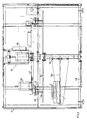
- FIGS 3 to 7 show various embodiments of an installation provided with at least one dispensing device 1, 2 as just described above.
- This installation is intended to automatically deliver precise quantities of one or more liquids in one or more container (s) 6 in order to form, for example, mixtures of different liquid products.
- the installation comprises a first support assembly 31 on which are mounted several dispensing devices 1, 2 and a second support assembly on which is or are mounted the the drive members 13a, 15, 27, 28 of the actuation mechanisms.
- At this installation are associated with at least one container 6 of liquid (s), at least one indicator element 7 of the quantity of liquid in the container 3 which is capable of emitting a signal representative of this quantity to the computation and control unit 10, programmable able to command and control according to the data of its program, the driving organ (s) of the mechanism (s) actuating the shutter element and the impulse means of each device distributor.
- the support assemblies 31, 32 are movable one relative to the other and at least one of the two support assemblies is mobilized relative to the other by a drive unit controlled by the calculation and control unit 10 so that are positioned facing each other the driving member (s) of the mechanisms actuator and the actuator rod (s) of the selected dispensing device.
- the dispensing devices 1, 2 are disposed on the first support assembly 31 at a constant interval along a circumference of circle and radially with respect to the latter so as to form a crown.
- these devices may be arranged at constant intervals along a straight line or well according to a curve if the geometric constraints of the location of the installation impose such a configuration
- the second set support will be mobile and will consist of a trolley that can be moved both in height and parallel to the alignment formed by distributor devices. The movements of this carriage in relation to the dispensing devices, as well as its positioning opposite the dispenser selected will be piloted and controlled by the control and command unit 10.
- the dispensing devices may also be arranged at non-constant intervals, some others.
- the second set support 32 is arranged in the first and the rod (s) 12, 14, 25 of the mechanism (s) of actuation of each dispensing element 1, 2 is or are horizontal (s) and radial (s) at the crown formed by the dispensing devices.
- the first support assembly 31 is fixed and the second is mobilized by the driving organ.
- a reverse arrangement namely a second fixed support assembly and a first mobile support assembly actuated by the drive member.
- the first support assembly 31 is constituted by an endless wall 33, determining a cylindrical volume in which is housed the second support assembly 32.
- This endless wall receives an upper wall 34 in the form of a circular disc and a lower wall 35 also in the form circular disc. These upper and lower walls close off in the upper part and in the lower part the cylindrical volume which delimits the endless wall 33.
- the enclosure formed by these walls 33, 34 and 35 is supported by an appropriate base, not shown.
- To the external cylindrical face of the endless wall 33 is fixed by any means known to those skilled in the art, the rigid body 11 of each dispensing device 1 fitted to the installation.
- the endless wall 33 is equipped with two radial through holes. In one of these holes is engaged the rod 12 of the closure element 8 and in the other the pusher 14 of the impulse means 9.
- the second support assembly 32 comprises an enclosure 32a forming a box parallelepiped, provided with a horizontal upper wall 36 and a lower wall horizontal 37 each provided along a common vertical axis with a through hole in which is mounted a rotation guide bearing on a vertical shaft 38 integral with the first support assembly 31 and more precisely walls 33 and 34 of the latter.
- This box is arranged centrally relative to the crown formed by the dispensing devices 1.
- the two upper and lower walls 37, 38 are joined to each other by at least two side walls 39, 40, diametrically opposite, normal to the same intersecting axis and perpendicular to the longitudinal axis of the guide shaft 38.
- the first of these walls, the wall 39, along a horizontal axis radial to the guide shaft 38 and radial to the first assembly 31, is provided with a through hole in which is engaged a ring provided with a bore crossing of polygonal cross section and developing along a horizontal axis radial to the shaft guide and radial to the crown formed by the distributor devices.
- This shaft receives fixing, in the form of sheath 41, a fixed toothed crown 42 with which is intended to cooperate in meshing with a toothed pinion 43 wedged on the horizontal output shaft of a member motor for rotating the second support assembly 32 around the guide shaft 38.
- This motor member is integral with the form of sheath and is fixed to the front of this latter. by any means known to those skilled in the art.
- This motor member is constituted for example by a electric stepper motor controlled by the command and control unit 10.
- this driving member is constituted by the driving member 13a of the mechanism actuation 13.
- this motor comprises a through shaft for receiving according to one from its ends the pinion 43 and according to the other end, outside the enclosure, and in regarding the distributor devices the coupling end piece 13b to the rod 12.
- sheath 41 carries externally to the enclosure 32a and facing the distributor devices, the drive member 13a with end piece 13b for actuating the element shutter 8 while the enclosure 32a under the aforementioned actuating member carries the member motor 15 of the actuation mechanism of the pulse means 9.
- the drive member 13a for rotating the second support assembly is controlled by unit 10 so as to move the actuating mechanisms towards the dispensing device chosen and immobilize them temporarily in the axis of the rods 12 and pusher 14.
- the traversing axis of the drive member 13a is associated with an encoder of a type known, connected by a suitable electrical line to the control and command unit for deliver to this last signal representative of the angular position of the second set in the first.
- the sleeve form 41 is slidably mounted in the through bore of the ring, and the lights 41c, through, practiced in the lower and upper walls of the sleeve shape 41 are oblong and oriented so that their longitudinal axis develops radially and secantly to the longitudinal axis of symmetry of the tree guide 38.
- an actuating member 41d of the jack type, under the action of which the form of sheath 41 is moved in the bore of the ring either to the distributor device 2 selected so that the coupling end 13b that the motor member 13a carries is coupled to the rod 12 of the shutter element 8 and the pinion 43 either uncoupled from the crown 42, or in the opposite direction so that the coupling end 13b is uncoupled from the rod 12 of the shutter element 8 and the pinion 43 coupled to the ring gear 42.
- the container 6 and the indicator element 7 of the amount of liquid in said container are fixed relative to the first support assembly 31 and occupy a lower and coaxial position relative to the crown formed by the devices distributors 1.
- the pipes of these devices in the lower part are bent so as to come to be located by their delivery nozzle 5 above the container 6. It should be noted that the pipes by their lower part are of equal dimensions and bent according to the same angle. This characteristic improves the repeatability of the assay results
- the installation as described can also use dispensing devices 2 according to the second embodiment.
- Figure 5 is shown an installation equipped with dispensing devices 2 according to the second embodiment.
- the first support assembly 31 comprises a horizontal plate 45 carried by and in a three-dimensional structure formed by assembling uprights and crosspieces arranged along the edges of a rectangular parallelepiped.
- This structure receives fixed walls of cover defining a parallelepiped volume in which the second is placed support assembly.
- This volume is provided with an access opening with which is associated a movable curtain, shutter or a hatch.
- the honzontale 45 plate receives in fixing the valve body of each distributor device 2 fitted to the installation.
- the valve bodies are arranged at regular intervals from one another according to the circle circumference so as to form a circular crown and are oriented so that their actuating rod 25 is radial to the formed crown and is oriented towards the center of the latter and towards the second support assembly 32.
- the second support assembly 32 comprises a vertical shaft 46 to which is fixed radially a support arm 47 carrying at a distance from the shaft 46, the drive member 28 with cam 27 of the impulse means 9 and actuation of the shutter element 8.
- the arm extends on either side of the shaft and carries opposite the drive member 28, a balancing mass.
- the vertical shaft 46 is engaged by its lower end in a rotation guide bearing, fixed to a lower plate 48 secured to the first support element 31 and is coupled by its upper end to the vertical output shaft of a drive member 49 for driving rotation, which is fixed by its housing to a frame integral with the first support assembly.
- This motor member constituted for example by a stepping electric motor is connected by a power line suitable for the control and command unit 10 so as to be controlled by the latter and position on demand, the arm 47 and the drive member 28 with cam 27 in view of the dispensing device selected for the distribution in the container 6, of the quantity required liquid.
- the body of each dispensing device is provided with a hole blind open on its horizontal upper face and a vertical pneumatic cylinder is provided carried by the arm on the side of its balancing mass and intended by its rod when activated at penetrate into the blind bore of the distributor body diametrically opposite to that selected.
- the shaft 46 between the support arm 47 and its upper end is engaged in a guide bearing mounted in the through hole of the horizontal plate 45 of the first support assembly 31.
- the shaft 46 is centered relative to the crown formed by the bodies of valve of the distributors which are oriented so that their stem 25 develops so radial to the shaft 46 and is turned towards the latter.
- the downstream section of the pipe of each dispensing device is engaged in a through hole of the support plate 45 to come to be located, by the distribution nozzle 5, above a second horizontal support plate 50 disposed under the first and at spacing of the latter, this second support plate being rigidly fixed to the shaft drive 46 so as to be rotated with the support arm 47, the container 6 and element 7 indicating the quantity of liquid in the container being installed on the second platinum.
- the container by its opening is positioned on this plate so as to be in the axis that is to say below the delivery nozzle 5 of the dispensing device selected for the delivery of a metered quantity of the liquid contained in the reservoir associated with this device distributor.
- the position of the plate 50 is adjustable along the axis in order to be able to receive containers of different heights.
- the pipe sections 4b are all straight, vertical and equal lengths. These provisions make it possible to improve the repeatability of the results of the assays.
- the second support assembly is equipped with a plate protective 51 horizontal fixed to the drive shaft 46.
- This plate has an edge peripheral raised and projecting on its upper face a boss. This boss and the plate are crossed right through by a single vertical drilling. This drilling, by rotation of the shaft, is taken along the axis of the nozzle 5 of the selected distributor device and allows the flow of liquid from the nozzle 5 to the container.
- this plate 51 is to recover and retain, thanks to its raised edge, the residual liquid flows and to prevent them from contaminating the composition made, or in progress and distorting the dosage.
- the rotary shaft 46 is associated with an encoder of a known type, connected by an appropriate power line, to the control and command unit to deliver to this last a signal representative of the angular position of the second set in the first.
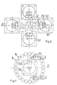
- the two support assemblies 31, 32 are fixed relative to each other, and the first assembly support receives in fixation at least a group of two of dispensing device 2, both dispensing devices of the group being arranged in parallel and symmetrical with respect to to a vertical geometric plane P and being oriented so that their actuating rods 25 are facing the same direction.
- a its own actuation mechanism fixed on the second support assembly and constituted a drive member 52 on the output shaft of which a cam 53 is wedged.
- the output shaft of the driving member 52 of the actuating mechanism is arranged vertically and the axis geometric rotation of this output shaft is arranged in the vertical geometric plane of symmetry P.
- the cam set in rotation and translation on the output shaft, has two vertical cam surfaces arranged symmetrically to a vertical plane containing the axis of rotation of the motor shaft, said cam by one of its cam surfaces being intended to be brought by the motor member under pressure against the actuating rod of the pulse and valve means of one of the two devices ei by the other cam surface against the rod of the other device.
- the installation has several groups of distributors and that the two distributors of each group are arranged side by side. In this case, the cam surfaces are arranged according to two vertical planes forming an angle between them.
- the installation has only one group of dispensing devices. These dispensing devices are spaced from each other and the surfaces of the cam used are parallel to each other.
- each group of the installation in FIG. 6 will be associated with a device indicator 7 and a container 6.
Landscapes
- Chemical & Material Sciences (AREA)
- Chemical Kinetics & Catalysis (AREA)
- Physics & Mathematics (AREA)
- General Physics & Mathematics (AREA)
- Feeding, Discharge, Calcimining, Fusing, And Gas-Generation Devices (AREA)
- Filling Of Jars Or Cans And Processes For Cleaning And Sealing Jars (AREA)
- Weight Measurement For Supplying Or Discharging Of Specified Amounts Of Material (AREA)
- Infusion, Injection, And Reservoir Apparatuses (AREA)
- Containers And Packaging Bodies Having A Special Means To Remove Contents (AREA)
- Cable Accessories (AREA)
- Automatic Analysis And Handling Materials Therefor (AREA)
Applications Claiming Priority (5)
| Application Number | Priority Date | Filing Date | Title |
|---|---|---|---|
| FR9611004A FR2753190B1 (fr) | 1996-09-06 | 1996-09-06 | Dispositifs destines au prelevement automatique, gravitaire ou sous pression, de quantites tres precises de liquides, et permettant, entre autres, la realisation automatique de compositions |
| FR9611004 | 1996-09-06 | ||
| FR9706436A FR2763580B1 (fr) | 1997-05-23 | 1997-05-23 | Dispositifs destines au prelevement automatique, gravitaire ou sous pression, de quantites tres precises de liquides, et permettant, entre autres, la realisation automatique de compositions |
| FR9706436 | 1997-05-23 | ||
| PCT/FR1997/001582 WO1998009911A1 (fr) | 1996-09-06 | 1997-09-08 | Procede, dispositif et installation pour la distribution en quantites dosees de liquide |
Publications (2)
| Publication Number | Publication Date |
|---|---|
| EP0929498A1 EP0929498A1 (fr) | 1999-07-21 |
| EP0929498B1 true EP0929498B1 (fr) | 2001-11-21 |
Family
ID=26232952
Family Applications (1)
| Application Number | Title | Priority Date | Filing Date |
|---|---|---|---|
| EP97940197A Expired - Lifetime EP0929498B1 (fr) | 1996-09-06 | 1997-09-08 | Procede, dispositif et installation pour la distribution en quantites dosees de liquide |
Country Status (10)
| Country | Link |
|---|---|
| US (1) | US6321798B1 (da) |
| EP (1) | EP0929498B1 (da) |
| JP (1) | JP3387933B2 (da) |
| AT (1) | ATE209160T1 (da) |
| AU (1) | AU4212097A (da) |
| DE (1) | DE69709768T2 (da) |
| DK (1) | DK0929498T3 (da) |
| ES (1) | ES2168670T3 (da) |
| PT (1) | PT929498E (da) |
| WO (1) | WO1998009911A1 (da) |
Families Citing this family (26)
| Publication number | Priority date | Publication date | Assignee | Title |
|---|---|---|---|---|
| US6637430B1 (en) * | 2000-06-16 | 2003-10-28 | Ponwell Enterprises Limited | Respiratory delivery system with power/medicament recharge assembly |
| FR2821615B1 (fr) | 2001-03-02 | 2004-12-03 | Jean Pierre Solignac | Dispositif pour la distribution dosee de precision de produits pateux ou liquides ou pulverulents |
| JP4024179B2 (ja) * | 2002-07-05 | 2007-12-19 | 株式会社リコー | トナー充填装置、およびトナー生産情報計測処理システム |
| ES2301275B1 (es) * | 2005-03-28 | 2009-05-01 | Iul, S.A. | Mejoras en diluidores gravimetricos. |
| CA2666181C (en) * | 2006-09-26 | 2015-11-24 | Marshall Thomas Waters | Dispensing apparatus and weighing process with control unit |
| ITBO20060836A1 (it) * | 2006-12-06 | 2008-06-07 | Marchesini Group Spa | Sistema tempo-pressione per il dosaggio di liquidi |
| DE102008016846A1 (de) * | 2008-04-01 | 2009-10-15 | Khs Ag | Verfahren und Vorrichtung zum Füllen von insbesondere großvolumigen Behältern |
| CH703127A1 (de) * | 2010-05-12 | 2011-11-15 | Tecan Trading Ag | Dispenser und Verfahren zum Abgeben von fliess- oder rieselfähigen Materialien. |
| DE102010023831A1 (de) * | 2010-06-10 | 2011-12-15 | Sig Technology Ag | Vorrichtung und Verfahren zur Befüllung von Produkten |
| KR101272446B1 (ko) * | 2011-10-28 | 2013-06-10 | 한형수 | 유체 토출 장치 |
| US9387504B2 (en) * | 2013-01-17 | 2016-07-12 | Nordson Corporation | Cartridge dispenser |
| ITBO20130699A1 (it) * | 2013-12-20 | 2015-06-21 | Marchesini Group Spa | Apparato per iniettare una quantita' dosata di liquido medicinale all'interno di un flacone |
| US10077764B2 (en) * | 2014-02-20 | 2018-09-18 | Stephen B. Maguire | Cart and method for dispensing liquid color |
| EP3093632B1 (en) * | 2015-05-11 | 2020-03-11 | Mettler-Toledo GmbH | Weighing device with application units |
| CN106074168B (zh) * | 2016-08-10 | 2023-05-02 | 山东新马制药装备有限公司 | 液料硬胶囊充填装置 |
| EA031600B1 (ru) * | 2016-12-08 | 2019-01-31 | Юрий Иванович ДРОБОТЯ | Способ контроля заполнения герметичной емкости текучей средой |
| EP3457094A1 (en) * | 2017-09-18 | 2019-03-20 | Balda Medical GmbH & Co. KG | A device for dosing and dispensing material and a method of operating such device |
| GB2568062B (en) * | 2017-11-02 | 2021-05-05 | Packaging Innovation Ltd | A container |
| US10850964B2 (en) * | 2019-03-22 | 2020-12-01 | Accenture Global Solutions Limited | System and method for filling containers with a precise amount of fluid |
| CN110759299B (zh) * | 2019-11-20 | 2024-02-27 | 广东科谷实验室技术研究院(有限合伙) | 一种强制互动的单片机系统及其工作方法 |
| CN111820280A (zh) * | 2020-07-23 | 2020-10-27 | 安徽曦强乳业集团有限公司 | 一种高钙牛奶及其生产工艺 |
| CN114560430A (zh) * | 2022-03-18 | 2022-05-31 | 重庆宇虹自动化仪表系统有限公司 | 自动化打酒装置 |
| CN115137560B (zh) * | 2022-07-29 | 2023-05-12 | 广州市天之敏生物科技有限公司 | 一种设有出血量计量功能的护理垫 |
| CN116175795B (zh) * | 2022-12-01 | 2023-08-29 | 福建凯邦锦纶科技有限公司 | 一种锦纶6生产用母粒原料定比配料设备及方法 |
| CN117228611B (zh) * | 2023-11-16 | 2024-01-19 | 四川嘉智生态科技有限公司 | 一种多品种液体分装机 |
| CN119246467B (zh) * | 2024-12-04 | 2025-03-14 | 方溯计量检测(浙江)有限公司 | 一种折光仪的校准装置 |
Family Cites Families (17)
| Publication number | Priority date | Publication date | Assignee | Title |
|---|---|---|---|---|
| DE1152634B (de) * | 1959-03-24 | 1963-08-08 | Victor W Smirles | Auslassvorrichtung fuer Fluessigkeiten aus Behaeltern |
| SE345520B (da) * | 1969-03-14 | 1972-05-29 | Aga Ab | |
| US4030640A (en) * | 1975-11-10 | 1977-06-21 | Indicon Inc. | Method and apparatus for dispensing viscous materials |
| FR2421142A1 (fr) * | 1978-03-31 | 1979-10-26 | Evian Eaux Min | Procede et dispositif pour le remplissage de recipients avec des liquides plats |
| DE2918669A1 (de) * | 1978-06-13 | 1979-12-20 | Roman Schreck | Dosiereinrichtung |
| GR76098B (da) * | 1981-05-25 | 1984-08-03 | Douwe Egberts Tabaksfab | |
| DE3303583A1 (de) * | 1983-02-03 | 1984-08-09 | Wolfgang 4800 Bielefeld Suttner | Ventil einer spritzpistole |
| DE3332236A1 (de) * | 1983-09-07 | 1985-03-21 | Krönert Elektro GmbH, 5880 Lüdenscheid | Verfahren und vorrichtung zum abfuellen von getraenken |
| FR2615845B1 (fr) * | 1987-05-29 | 1989-11-17 | Perrier Sa Ets | Doseuse pour le traitement de boissons en bouteilles |
| US5035350A (en) * | 1989-02-21 | 1991-07-30 | Minnesota Mining And Manufacturing Company | Method and apparatus for precision squeeze tube valving, pumping and dispensing of work fluid(s) |
| DE4112091A1 (de) * | 1991-04-12 | 1992-10-15 | Heller Guenther | Verfahren zur kontrolle einer fluessigkeitsmenge und vorrichtung |
| FR2677008B1 (fr) * | 1991-05-31 | 1996-12-20 | Inf Lab | Dispositif a pompe peristaltique permettant de prelever, peser et melanger automatiquement des liquides. |
| US5228486A (en) * | 1992-05-29 | 1993-07-20 | Wilshire Partners | Control circuit and method for automatically dispensing beverages |
| DE4241073C1 (de) * | 1992-12-05 | 1994-06-01 | Satzinger Gmbh & Co | Apparat für die dosierte Abgabe von einem Fluid, insbesondere von einem Schmiermittelfluid |
| IT1272103B (it) * | 1993-03-17 | 1997-06-11 | I A S Ind Automation Systems A | Apparecchiatura per l'erogazione di una sostanza fluida,in quantita' dosate |
| DE4314343C2 (de) * | 1993-04-30 | 1995-03-16 | Vermes Technik Gmbh & Co Kg | Vorrichtung zur Dosierung von Flüssigkeiten |
| FR2711610B1 (fr) * | 1993-10-29 | 1996-02-02 | Andre J J Graffin | Procédé de remplissage d'un récipient avec un poids net de référence. |
-
1997
- 1997-09-08 ES ES97940197T patent/ES2168670T3/es not_active Expired - Lifetime
- 1997-09-08 WO PCT/FR1997/001582 patent/WO1998009911A1/fr not_active Ceased
- 1997-09-08 AU AU42120/97A patent/AU4212097A/en not_active Abandoned
- 1997-09-08 JP JP51232198A patent/JP3387933B2/ja not_active Expired - Lifetime
- 1997-09-08 EP EP97940197A patent/EP0929498B1/fr not_active Expired - Lifetime
- 1997-09-08 PT PT97940197T patent/PT929498E/pt unknown
- 1997-09-08 DK DK97940197T patent/DK0929498T3/da active
- 1997-09-08 US US09/254,337 patent/US6321798B1/en not_active Expired - Lifetime
- 1997-09-08 AT AT97940197T patent/ATE209160T1/de active
- 1997-09-08 DE DE69709768T patent/DE69709768T2/de not_active Expired - Lifetime
Also Published As
| Publication number | Publication date |
|---|---|
| AU4212097A (en) | 1998-03-26 |
| US6321798B1 (en) | 2001-11-27 |
| ATE209160T1 (de) | 2001-12-15 |
| ES2168670T3 (es) | 2002-06-16 |
| EP0929498A1 (fr) | 1999-07-21 |
| DK0929498T3 (da) | 2002-04-02 |
| JP2000507533A (ja) | 2000-06-20 |
| WO1998009911A1 (fr) | 1998-03-12 |
| DE69709768T2 (de) | 2002-07-18 |
| DE69709768D1 (de) | 2002-02-21 |
| JP3387933B2 (ja) | 2003-03-17 |
| PT929498E (pt) | 2002-05-31 |
Similar Documents
| Publication | Publication Date | Title |
|---|---|---|
| EP0929498B1 (fr) | Procede, dispositif et installation pour la distribution en quantites dosees de liquide | |
| EP0954485B1 (fr) | Dispositif de distribution de produit fluide avec systeme d'obturation | |
| FR2756811A1 (fr) | Dispositif de distribution de produit fluide du type bicomposant | |
| EP1381557B1 (fr) | Tete de remplissage | |
| EP0350376B1 (fr) | Valve doseuse pour aerosols | |
| EP0592312B1 (fr) | Doseur, robinet doseur, appareil de dosage en cadence de liquide | |
| EP1061807B1 (fr) | Appareil pour la distribution de quantites predeterminees de produits liquides et/ou pateux | |
| WO2022189742A1 (fr) | Dispositif de distribution nasale de produit fluide | |
| FR2467149A1 (fr) | Distributeur-doseur pour produits pateux et liquides | |
| CA2072402C (fr) | Dispositif pour prelever et restituer une quantite predeterminee et constante d'un liquide | |
| EP2291633B1 (fr) | Appareil de dilution d'un échantillon | |
| FR2646652A1 (fr) | Dispositif de delivrance d'un produit quelconque contenu dans un reservoir a paroi deformable | |
| EP0251863A1 (fr) | Ensemble doseur pour un produit pâteux ou semi-liquide | |
| WO2020104748A1 (fr) | Dispositif securise de comptage et de distribution d'objets | |
| FR2915971A1 (fr) | Dispositif de type bouchon doseur, pour la distribution d'un volume determine d'un liquide conditionne en bouteille. | |
| FR2655319A1 (fr) | Introducteur-doseur pour produits pulverulents, granules, pateux ou similaires. | |
| FR2562444A1 (fr) | Dispositif de dosage manuel d'un produit liquide | |
| EP0076222B1 (fr) | Dispositif de pipetage automatique | |
| EP0603076A1 (fr) | Dispositif de manipulation d'une seringue et automate d'analyse biologique comportant un tel dispositif | |
| EP0576762B1 (fr) | Dispositif pour délivrer une quantité déterminée de liquide | |
| EP2786102B1 (fr) | Dispositif de distribution de poudre, bouchon pour un tel dispositif et station de travail comprenant un tel dispositif | |
| WO1990008707A1 (fr) | Distributeur verseur et/ou doseur pour liquide ou poudre | |
| FR2763580A1 (fr) | Dispositifs destines au prelevement automatique, gravitaire ou sous pression, de quantites tres precises de liquides, et permettant, entre autres, la realisation automatique de compositions | |
| FR2510749A1 (fr) | Procede et dispositif permettant de prelever un liquide stocke dans un recipient reservoir et d'en delivrer une quantite determinee en vue de son utilisation et installation de dosage equipee d'un tel dispositif | |
| EP1418415B1 (fr) | Doseur pour liquide contenu dans un récipient |
Legal Events
| Date | Code | Title | Description |
|---|---|---|---|
| PUAI | Public reference made under article 153(3) epc to a published international application that has entered the european phase |
Free format text: ORIGINAL CODE: 0009012 |
|
| 17P | Request for examination filed |
Effective date: 19990406 |
|
| AK | Designated contracting states |
Kind code of ref document: A1 Designated state(s): AT BE CH DE DK ES FI FR GB GR IE IT LI LU MC NL PT SE |
|
| 17Q | First examination report despatched |
Effective date: 19991105 |
|
| GRAG | Despatch of communication of intention to grant |
Free format text: ORIGINAL CODE: EPIDOS AGRA |
|
| GRAG | Despatch of communication of intention to grant |
Free format text: ORIGINAL CODE: EPIDOS AGRA |
|
| GRAH | Despatch of communication of intention to grant a patent |
Free format text: ORIGINAL CODE: EPIDOS IGRA |
|
| GRAH | Despatch of communication of intention to grant a patent |
Free format text: ORIGINAL CODE: EPIDOS IGRA |
|
| GRAA | (expected) grant |
Free format text: ORIGINAL CODE: 0009210 |
|
| AK | Designated contracting states |
Kind code of ref document: B1 Designated state(s): AT BE CH DE DK ES FI FR GB GR IE IT LI LU MC NL PT SE |
|
| REF | Corresponds to: |
Ref document number: 209160 Country of ref document: AT Date of ref document: 20011215 Kind code of ref document: T |
|
| REG | Reference to a national code |
Ref country code: CH Ref legal event code: EP |
|
| REG | Reference to a national code |
Ref country code: IE Ref legal event code: FG4D Free format text: FRENCH |
|
| REG | Reference to a national code |
Ref country code: GB Ref legal event code: IF02 |
|
| REF | Corresponds to: |
Ref document number: 69709768 Country of ref document: DE Date of ref document: 20020221 |
|
| REG | Reference to a national code |
Ref country code: CH Ref legal event code: NV Representative=s name: BOVARD AG PATENTANWAELTE |
|
| GBT | Gb: translation of ep patent filed (gb section 77(6)(a)/1977) |
Effective date: 20020222 |
|
| REG | Reference to a national code |
Ref country code: DK Ref legal event code: T3 |
|
| REG | Reference to a national code |
Ref country code: PT Ref legal event code: SC4A Free format text: AVAILABILITY OF NATIONAL TRANSLATION Effective date: 20020219 |
|
| REG | Reference to a national code |
Ref country code: ES Ref legal event code: FG2A Ref document number: 2168670 Country of ref document: ES Kind code of ref document: T3 |
|
| REG | Reference to a national code |
Ref country code: GR Ref legal event code: EP Ref document number: 20020400715 Country of ref document: GR |
|
| PLBE | No opposition filed within time limit |
Free format text: ORIGINAL CODE: 0009261 |
|
| STAA | Information on the status of an ep patent application or granted ep patent |
Free format text: STATUS: NO OPPOSITION FILED WITHIN TIME LIMIT |
|
| 26N | No opposition filed | ||
| REG | Reference to a national code |
Ref country code: PT Ref legal event code: TE4A Free format text: JEAN PIERRE SOLIGNAC FR Effective date: 20031117 |
|
| REG | Reference to a national code |
Ref country code: FR Ref legal event code: CA |
|
| REG | Reference to a national code |
Ref country code: CH Ref legal event code: PFA Owner name: JEAN PIERRE SOLIGNAC Free format text: JEAN PIERRE SOLIGNAC#10, RUE DU TRUC D'ANIS#34270 SAINT MATHIEU DE TREVIERS (FR) -TRANSFER TO- JEAN PIERRE SOLIGNAC#10, RUE DU TRUC D'ANIS#34270 SAINT MATHIEU DE TREVIERS (FR) |
|
| PG25 | Lapsed in a contracting state [announced via postgrant information from national office to epo] |
Ref country code: IT Free format text: LAPSE BECAUSE OF NON-PAYMENT OF DUE FEES Effective date: 20100908 |
|
| PGRI | Patent reinstated in contracting state [announced from national office to epo] |
Ref country code: IT Effective date: 20110616 |
|
| REG | Reference to a national code |
Ref country code: FR Ref legal event code: PLFP Year of fee payment: 19 |
|
| PGFP | Annual fee paid to national office [announced via postgrant information from national office to epo] |
Ref country code: GB Payment date: 20150928 Year of fee payment: 19 Ref country code: PT Payment date: 20150821 Year of fee payment: 19 Ref country code: ES Payment date: 20150928 Year of fee payment: 19 Ref country code: MC Payment date: 20150820 Year of fee payment: 19 Ref country code: CH Payment date: 20150928 Year of fee payment: 19 Ref country code: IE Payment date: 20150929 Year of fee payment: 19 Ref country code: DE Payment date: 20150806 Year of fee payment: 19 Ref country code: FI Payment date: 20150929 Year of fee payment: 19 |
|
| PGFP | Annual fee paid to national office [announced via postgrant information from national office to epo] |
Ref country code: SE Payment date: 20150929 Year of fee payment: 19 Ref country code: AT Payment date: 20150819 Year of fee payment: 19 Ref country code: LU Payment date: 20151001 Year of fee payment: 19 Ref country code: BE Payment date: 20150805 Year of fee payment: 19 Ref country code: GR Payment date: 20150929 Year of fee payment: 19 |
|
| PGFP | Annual fee paid to national office [announced via postgrant information from national office to epo] |
Ref country code: IT Payment date: 20150923 Year of fee payment: 19 Ref country code: DK Payment date: 20150928 Year of fee payment: 19 |
|
| PGFP | Annual fee paid to national office [announced via postgrant information from national office to epo] |
Ref country code: NL Payment date: 20150926 Year of fee payment: 19 Ref country code: FR Payment date: 20150928 Year of fee payment: 19 |
|
| PG25 | Lapsed in a contracting state [announced via postgrant information from national office to epo] |
Ref country code: BE Free format text: LAPSE BECAUSE OF NON-PAYMENT OF DUE FEES Effective date: 20160930 |
|
| REG | Reference to a national code |
Ref country code: DE Ref legal event code: R119 Ref document number: 69709768 Country of ref document: DE |
|
| REG | Reference to a national code |
Ref country code: DK Ref legal event code: EBP Effective date: 20160930 |
|
| PG25 | Lapsed in a contracting state [announced via postgrant information from national office to epo] |
Ref country code: SE Free format text: LAPSE BECAUSE OF NON-PAYMENT OF DUE FEES Effective date: 20160909 Ref country code: FI Free format text: LAPSE BECAUSE OF NON-PAYMENT OF DUE FEES Effective date: 20160908 Ref country code: MC Free format text: LAPSE BECAUSE OF NON-PAYMENT OF DUE FEES Effective date: 20160930 |
|
| REG | Reference to a national code |
Ref country code: CH Ref legal event code: PL |
|
| REG | Reference to a national code |
Ref country code: SE Ref legal event code: EUG |
|
| REG | Reference to a national code |
Ref country code: NL Ref legal event code: MM Effective date: 20161001 |
|
| REG | Reference to a national code |
Ref country code: AT Ref legal event code: MM01 Ref document number: 209160 Country of ref document: AT Kind code of ref document: T Effective date: 20160908 |
|
| GBPC | Gb: european patent ceased through non-payment of renewal fee |
Effective date: 20160908 |
|
| PG25 | Lapsed in a contracting state [announced via postgrant information from national office to epo] |
Ref country code: PT Free format text: LAPSE BECAUSE OF NON-PAYMENT OF DUE FEES Effective date: 20170308 |
|
| REG | Reference to a national code |
Ref country code: IE Ref legal event code: MM4A |
|
| PG25 | Lapsed in a contracting state [announced via postgrant information from national office to epo] |
Ref country code: NL Free format text: LAPSE BECAUSE OF NON-PAYMENT OF DUE FEES Effective date: 20161001 |
|
| REG | Reference to a national code |
Ref country code: FR Ref legal event code: ST Effective date: 20170531 |
|
| REG | Reference to a national code |
Ref country code: GR Ref legal event code: ML Ref document number: 20020400715 Country of ref document: GR Effective date: 20170411 |
|
| PG25 | Lapsed in a contracting state [announced via postgrant information from national office to epo] |
Ref country code: IE Free format text: LAPSE BECAUSE OF NON-PAYMENT OF DUE FEES Effective date: 20160908 Ref country code: LI Free format text: LAPSE BECAUSE OF NON-PAYMENT OF DUE FEES Effective date: 20160930 Ref country code: GR Free format text: LAPSE BECAUSE OF NON-PAYMENT OF DUE FEES Effective date: 20170411 Ref country code: CH Free format text: LAPSE BECAUSE OF NON-PAYMENT OF DUE FEES Effective date: 20160930 Ref country code: GB Free format text: LAPSE BECAUSE OF NON-PAYMENT OF DUE FEES Effective date: 20160908 Ref country code: DE Free format text: LAPSE BECAUSE OF NON-PAYMENT OF DUE FEES Effective date: 20170401 Ref country code: FR Free format text: LAPSE BECAUSE OF NON-PAYMENT OF DUE FEES Effective date: 20160930 |
|
| PG25 | Lapsed in a contracting state [announced via postgrant information from national office to epo] |
Ref country code: AT Free format text: LAPSE BECAUSE OF NON-PAYMENT OF DUE FEES Effective date: 20160908 Ref country code: LU Free format text: LAPSE BECAUSE OF NON-PAYMENT OF DUE FEES Effective date: 20160908 Ref country code: IT Free format text: LAPSE BECAUSE OF NON-PAYMENT OF DUE FEES Effective date: 20160908 |
|
| REG | Reference to a national code |
Ref country code: BE Ref legal event code: MM Effective date: 20160930 |
|
| PG25 | Lapsed in a contracting state [announced via postgrant information from national office to epo] |
Ref country code: PT Free format text: LAPSE BECAUSE OF EXPIRATION OF PROTECTION Effective date: 20170918 Ref country code: DK Free format text: LAPSE BECAUSE OF NON-PAYMENT OF DUE FEES Effective date: 20160930 |
|
| REG | Reference to a national code |
Ref country code: ES Ref legal event code: FD2A Effective date: 20180507 |
|
| PG25 | Lapsed in a contracting state [announced via postgrant information from national office to epo] |
Ref country code: ES Free format text: LAPSE BECAUSE OF NON-PAYMENT OF DUE FEES Effective date: 20160909 |
|
| PG25 | Lapsed in a contracting state [announced via postgrant information from national office to epo] |
Ref country code: PT Free format text: LAPSE BECAUSE OF EXPIRATION OF PROTECTION Effective date: 20150908 |
|
| P01 | Opt-out of the competence of the unified patent court (upc) registered |
Effective date: 20230530 |