EP0929765B1 - Garniture d'etancheite a labyrinthe et procede d'assemblage correspondant - Google Patents
Garniture d'etancheite a labyrinthe et procede d'assemblage correspondant Download PDFInfo
- Publication number
- EP0929765B1 EP0929765B1 EP97911718A EP97911718A EP0929765B1 EP 0929765 B1 EP0929765 B1 EP 0929765B1 EP 97911718 A EP97911718 A EP 97911718A EP 97911718 A EP97911718 A EP 97911718A EP 0929765 B1 EP0929765 B1 EP 0929765B1
- Authority
- EP
- European Patent Office
- Prior art keywords
- stator
- engagement
- rotator
- sealing device
- annular
- Prior art date
- Legal status (The legal status is an assumption and is not a legal conclusion. Google has not performed a legal analysis and makes no representation as to the accuracy of the status listed.)
- Expired - Lifetime
Links
- 238000007789 sealing Methods 0.000 title claims abstract description 71
- 238000000034 method Methods 0.000 title abstract description 6
- 239000000356 contaminant Substances 0.000 claims description 13
- 230000000295 complement effect Effects 0.000 claims description 12
- 239000000314 lubricant Substances 0.000 claims description 7
- 230000000750 progressive effect Effects 0.000 claims description 6
- 239000012530 fluid Substances 0.000 claims description 5
- 230000001050 lubricating effect Effects 0.000 claims description 2
- 230000037361 pathway Effects 0.000 description 15
- 230000004888 barrier function Effects 0.000 description 6
- 239000000463 material Substances 0.000 description 6
- 238000010276 construction Methods 0.000 description 5
- 230000014759 maintenance of location Effects 0.000 description 4
- 229920001343 polytetrafluoroethylene Polymers 0.000 description 3
- 239000004810 polytetrafluoroethylene Substances 0.000 description 3
- 230000000694 effects Effects 0.000 description 2
- 230000003993 interaction Effects 0.000 description 2
- 238000007599 discharging Methods 0.000 description 1
- 230000005489 elastic deformation Effects 0.000 description 1
- 238000010438 heat treatment Methods 0.000 description 1
- 239000010687 lubricating oil Substances 0.000 description 1
- 230000007246 mechanism Effects 0.000 description 1
- 230000005012 migration Effects 0.000 description 1
- 238000013508 migration Methods 0.000 description 1
- 238000012856 packing Methods 0.000 description 1
- -1 polytetrafluoroethylene Polymers 0.000 description 1
- 230000002000 scavenging effect Effects 0.000 description 1
- 239000012815 thermoplastic material Substances 0.000 description 1
Images


Classifications
-
- F—MECHANICAL ENGINEERING; LIGHTING; HEATING; WEAPONS; BLASTING
- F16—ENGINEERING ELEMENTS AND UNITS; GENERAL MEASURES FOR PRODUCING AND MAINTAINING EFFECTIVE FUNCTIONING OF MACHINES OR INSTALLATIONS; THERMAL INSULATION IN GENERAL
- F16J—PISTONS; CYLINDERS; SEALINGS
- F16J15/00—Sealings
- F16J15/44—Free-space packings
- F16J15/447—Labyrinth packings
- F16J15/4472—Labyrinth packings with axial path
- F16J15/4474—Pre-assembled packings
Definitions
- the subject invention is related to mechanical joint packing devices, and more particularly, to a labyrinth sealing device for providing a dynamic seal between a rotating shaft and a bearing housing, and a method of assembling the sealing device.
- Labyrinth type rotary shaft seals are well known in the art. Typically, these devices include two concentric ring structures which define a rotator and a stator. The rotator is sealing engaged with a rotating shaft, and the stator is sealingly engaged with a bearing housing. Specifically contoured pathways or grooves are formed in the interior surfaces of the seal rings to create a maze or labyrinth extending between the exterior of the bearing housing to the interior of the bearing housing.
- the labyrinth pathway serves as a hydrodynamic barrier to maintain fluid lubricants within the bearing housing and prevent contaminants from entering the bearing housing. The more elaborate the pathway, the less chance there is that contaminating materials will pass through the structure and into the bearing housing.
- One way of making a more elaborate pathway is to increase the amount of surface area that must be traversed by contaminating materials, i . e ., increase the length of the pathway.
- the extent of the surface area of the labyrinth pathway will be limited by the degree of mechanical interlock between the two components of the device upon assembly. If the interlocking contact area between the components is relatively small, there will be less surface area to form a labyrinth pathway therebetween. Conversely, if the interlocking contact area between the two components is relatively large, there will be a greater surface area to form a more elaborate labyrinth pathway between the two components.
- EP-A-0 027 539 discloses a generic dynamic labyrinth sealing device comprising a stator and a rotor with engagement flanges and means for interlocking the stator and the rotor.
- the rotor is interlocked with the stator by a series of slits in the stator which allow the stator to be expanded over the rotor, then returned to its original shape, thereby locking them together.
- the annular stator comprises a body portion and a cover portion.
- the cover portion has a radially inner engagement portion and the annular rotor has a radially outer engagement portion.
- the first flange on the stator projects radially inward and comprises one of the sealing flanges.
- GB-A-2 219 475 describes a dynamic sealing device for placement between a rotating shaft and a bearing housing comprising a stator and a rotor, each with engagement flanges.
- the stator is made of two pieces which are fitted around the rotor and secured with an O-ring so as to couple the two halves together.
- the first flange of the stator projects radially inward from a radially inner leading edge toward the flanges of the rotor.
- the subject invention is directed to a dynamic labyrinth sealing device for placement between a rotating shaft and a bearing housing in accordance with claim 1.
- the device includes a stator for sealingly engaging the bearing housing and a rotator for sealingly engaging the rotating shaft.
- An elaborate labyrinth pathway is defined between the stator and rotator for preventing contaminants from passing through the structure.
- the stator has an annular engagement flange on a radially inner portion thereof and the rotator has an annular engagement flange on a radially outer portion thereof.
- the stator annular engagement flange and the rotator annular engagement flange mechanically interlock the stator and the rotator. Once interlocked, the annular engagement flanges form part of the labyrinth pathway.
- the outer radial engagement notch is formed in the stator engagement flange and an inner radial engagement notch is formed in the rotator engagement flange.
- the outer radial engagement notch and the inner radial engagement notch include complementary angled engagement surfaces.
- the stator engagement flange and the rotator engagement flange each have opposed leading and trailing axial surfaces, and the complementary angled surfaces of the radial engagement notches are dimensioned and configured to facilitate progressive opposed lateral deflection of the engagement flanges and effectuate juxtaposition of the leading axial surface of the rotator engagement flange and the trailing axial surface of the stator engagement flange.
- At least one annular recess is formed in a radially outer portion of the stator for supporting an elastomeric O-ring between the stator and the bearing housing.
- at least one annular recess is formed in a radially inner portion of the rotator for supporting an elastomeric O-ring between the rotator and the rotating shaft.
- at least one annular groove is formed in the radially inner portion of the stator, in a location spaced from the engagement flange thereof, for receiving lubricating fluid from the bearing housing, and an axial drainage port is associated with the annular groove.
- At least one annular groove is formed in the radially outer portion of the rotator, in a location spaced from the engagement flange thereof, for capturing contaminants drawn into the sealing device from outside the bearing housing.
- a radial exhaust slot is preferably formed in the stator to facilitate the expulsion of captured contaminants from the sealing device.
- An annular sealing lip projects from a leading edge of the radially outer portion of the stator for sealingly engaging a leading edge of the radially outer portion of the rotator, providing an additional barrier to contaminants.
- stator and rotator To assemble the sealing device of the subject invention, the stator and rotator must be properly oriented with respect to one another placing the angled engagement surfaces of the radial engagement notches into abutting contact. Then, the rotator and the stator are rotated relative to one another so that the engagement flanges undergo progressive lateral deflection and the leading surface of the rotator engagement flange is moved into juxtaposition with the trailing surface of the stator engagement flange, thereby mechanically interlocking the stator and rotator.
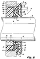
- sealing device 10 is employed between a rotating axial shaft 12 and a bearing housing 14 containing a fluid lubricant to prevent leakage of lubricants from the housing and entry of contaminants into the housing. More particularly, the device is designed as a two-piece labyrinth seal which operates to prevent the migration of the lubricants and/or the contaminants in either direction.
- the device is preferably formed from polytetrafluoroethylene (PTFE) although alternative self-lubricating materials of construction may also be employed. The selected material of construction must however, exhibit memory retention after elastic deformation.
- inboard shall refer to the side of sealing device 10 or component part thereof that is closest to the interior of bearing housing 14, while the term “outboard” shall refer to the side of sealing device 10 or component part thereof that is closest to the exterior of bearing housing 14.
- the terms “trailing” and “leading,” when used to describe the relative positions of certain component parts of the sealing device 10, shall have the same or substantially the same meaning as the terms “inboard” and “outboard,” respectively.
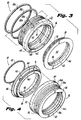
- sealing device 10 includes an annular stator 16 for sealingly engaging bearing housing 14 and an annular rotator 18 for sealingly engaging the axial shaft 12.
- the annular stator 16 is defined by an annular main body portion 20 and a forwardly extending annular cover portion 22 which are integrally formed with one another as a monolithic unit.
- the main body portion 20 includes a pair of annular slots 24a and 24b in a radially outer surface thereof for accommodating a pair of elastomeric sealing rings 26a and 26b designed to compressibly engage the inner periphery of the shaft bore 30 that extends through the wall of bearing housing 14 to secure stator 16 from rotation relative to the rotator 18.
- the annular cover portion 22 has a larger outer diameter that the main body portion 20 and the shaft bore 30 and resides outside of the bearing housing 14 with the shoulder surface 32 thereof abutting the exterior surface of the housing when installed.
- a pair of annular lubricant grooves 34a and 34b are defined in the radially inner surface of main body portion 20 for scavenging liquid lubricants that adhere to the rotating shaft during operation.
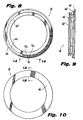
- an axially opening recess 36 is if formed in the main body portion 20, , which serves as a drain for the scavenged lubricants accumulated in grooves 34a and 34b.
- recess 36 is preferably positioned at a dead bottom center location with respect to the longitudinal axis of rotating shaft 12.
- cover portion 22 of stator 16 is dimensioned and configured to completely enclose and fully circumscribe annular rotator 18.
- the radially inner surface of cover portion 22 forms a stepped annular engagement area which defines an elaborate labyrinthine pathway designed to prevent the ingress of contaminants from the atmosphere into the bearing housing 14, and provides the structural interface to rotatably engage rotator 18.
- the stepped engagement area of stator 16 is defined by an inboard engagement channel 40, an outboard engagement channel 42, and a radial engagement lip 44.
- An annular land surface 46 is formed between engagement channels 40 and 42, and an annular engagement flange 48 is formed between the outboard engagement channel 42 and the radial engagement lip 44.
- outboard engagement channel 42 has a greater radial depth than inboard engagement channel 40.
- each of these structures accommodates a complementary structure formed in the radially outer surface of rotator 18.
- exhaust slot 50 extends from outboard engagement channel 42, through the annular cover portion 22 of stator 16, to the atmosphere, for discharging contaminants that may enter into the labyrinthine pathway created between the engagement surfaces of the stator and rotator.
- exhaust slot 50 is preferably positioned at a dead bottom center location with respect to the longitudinal axis of rotating shaft 12.
- rotator 18 is defined by an annular body portion 52 having an interior bore 54 dimensioned to accommodate axial shaft 12.
- An annular retention slot 56 is defined in the radially inner surface of body portion 42 to accommodate an elastomeric sealing ring 58 dimensioned to sealingly engage the outer periphery of axial shaft 12 and facilitate the movement of rotator 18 therewith, relative to stator 16 and bearing housing 14.
- a series of radially outwardly projecting flanges of varying radially dimension extend from the annular body portion 52 of rotator 18 to further define the labyrinth pathway of sealing device 10.
- These include a first inboard engagement flange 60 dimensioned and configured to interact with inboard engagement channel 40, an intermediate barrier flange 62 positioned in opposition to annular land surface 46, an outboard engagement flange 64 dimensioned and configured to interact with outboard engagement channel 42.
- Inboard engagement flange 60 has a greater radial height than intermediate barrier flange 62, while outboard engagement flange 64 has a greater radial height than both the inboard and intermediate flanges 60 and 62.
- rotator 18 also includes a outboard face plate 66 which, when engaged by radial engagement lip 44, encloses the labyrinth pathway defined between stator 16 and rotator 18, and which, together with engagement lip 44, form the primary barrier to contaminates entering bearing housing 14.
- engagement lip 44 is flexible with respect to outer periphery of cover portion 22, thus during assembly, lip 44 deflects radially outwardly to receive and sealingly engage outboard face plate 66.
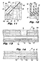
- enhanced sealing effects may also be provided by the inherent angularity of the inboard side 66a of face plate 66 (Fig. 12), which, due to its configuration, tends to lean against the outboard side of the annular engagement flange 48 of stator 16, forming an added barrier to contaminants.
- stator engagement notch 70 is formed in stator engagement flange 48, and a radially inwardly extending engagement notch 72 is formed in rotator engagement flange 64.
- Stator engagement notch 70 is formed with opposed angled engagement surfaces 70a and 70b, best seen in Fig.
- rotator engagement notch 72 is formed with opposed angled engagement notches 72a and 72b, best seen in Fig. 14. As will be discussed in greater detail hereinbelow, the coacting complementary angled engagement surfaces of notches 70 and 72 serve to initiate the mechanical assembly of sealing device 10.
- engagement notches could vary in size and configuration, ranging from the rather large wedge-shaped notches depicted in Fig. 15 to much smaller slots or even thin slits which would also effectively facilitate assembly of the device.
- stator 16 and rotator 18 are assembled through the mechanical interaction of engagement notches 70 and 72.
- stator 16 and rotator 18 are initially oriented relative to one another such that the stator engagement notch 70 is axially aligned with the rotator engagement notch 72.
- the two components are moved into juxtaposition, and complementary angled engagement surfaces 70a and 72b of engagement notches 70 and 72, respectively, are moved into abutting relationship with one another, as illustrated in Figs. 16 and 17.
- the two components of sealing device 10 could also be oriented such that complementary engagement surfaces 70b and 72a are moved into abutting relationship to initiate assembly rather than surfaces 70a and 72b.
- assembly of the sealing device 10 is effectuated by rotating the two components relative to one another, in the illustrated instance by moving the rotator relative to the stator in a clockwise direction.
- the two abutting complementary angled surfaces (70a and 72b) are urged past one another so that they operate as opposed camming surfaces or ramps, causing the progressive opposed lateral deflection of stator engagement flange 48 and rotator engagement flange 64, as best seen in Fig. 19.
- the leading surface (outboard side) of rotator engagement flange 64 is progressively moved into juxtaposition with the trailing surface (inboard side) of stator engagement flange 48.
- thermoplastic material from which the components of sealing device 10 is constructed exhibit shape memory retention.
- the preferred material of construction is PTFE.
Landscapes
- Engineering & Computer Science (AREA)
- General Engineering & Computer Science (AREA)
- Mechanical Engineering (AREA)
- Sealing Using Fluids, Sealing Without Contact, And Removal Of Oil (AREA)
- Electrical Discharge Machining, Electrochemical Machining, And Combined Machining (AREA)
- Heating, Cooling, Or Curing Plastics Or The Like In General (AREA)
- Motor Or Generator Frames (AREA)
Abstract
Claims (10)
- Garniture d'étanchéité dynamique à labyrinthe destinée à être placée entre un arbre tournant (12) et un boítier de palier (14) contenant un lubrifiant fluide, comprenant :caractérisée en ce que ladite bride de prise annulaire (48) du stator possède une encoche de prise (70) s'étendant radialement vers l'extérieur depuis le bord radialement intérieur de la bride de prise (48) du stator, et ladite bride de prise annulaire (64) du rotor possède une encoche de prise (72) s'étendant radialement vers l'intérieur depuis le bord radialement extérieur de la bride de prise (64) du rotor, et lesdites encoches de prise (70, 72) sont dimensionnées et configurées pour faciliter la juxtaposition axiale de la surface extérieure axiale de tête de ladite bride de prise (64) du rotor et de la surface intérieure axiale de queue de ladite bride de prise (48) du stator par une rotation relative dudit stator et dudit rotor (18) durant l'assemblage de ladite garniture d'étanchéité dynamique, afin de verrouiller mécaniquement ledit stator (16) et ledit rotor (18) l'un à l'autre.a) un stator (16) ayant une bride de prise annulaire (48) sur une partie radialement intérieure de celui-ci qui comprend des surfaces axiales de tête et de queue opposées ; etb) un rotor (18) ayant une bride de prise annulaire (64) sur une partie radialement extérieure de celui-ci qui comprend des surfaces axiales de tête et de queue opposées ;
- Garniture d'étanchéité dynamique à labyrinthe selon la revendication 1, dans laquelle ladite encoche de prise radiale extérieure (70) et ladite encoche de prise radiale intérieure (72) comprennent des surfaces de prise obliques complémentaires (70a, 70b, 72a, 72b).
- Garniture d'étanchéité dynamique à labyrinthe selon la revendication 2, caractérisé en ce que lesdites surfaces de prise obliques desdites encoches de prise radiales (70, 72) sont dimensionnées et configurées pour faciliter une déformation latérale opposée progressive desdites brides de prise (48, 64) afin d'effectuer la juxtaposition axiale de la surface axiale de tête de ladite bride de prise (64) du rotor et de ladite surface axiale de queue de ladite bride de prise du stator.
- Garniture d'étanchéité dynamique à labyrinthe selon la revendication 1, dans laquelle au moins un renfoncement annulaire (24a, b) est formé dans une partie radialement extérieure dudit stator (16) afin de soutenir un joint torique élastomère (26a, b) entre ledit stator (16) et ledit boítier de palier (14).
- Garniture d'étanchéité dynamique à labyrinthe selon la revendication 1, dans laquelle au moins un renfoncement annulaire (56) est formé dans une partie radialement intérieure dudit rotor (18) pour soutenir un joint torique élastomère (58) entre ledit rotor (18) et ledit arbre tournant (12).
- Garniture d'étanchéité dynamique à labyrinthe selon la revendication 1, dans laquelle au moins une gorge annulaire (34a, b) est formée dans ladite partie radialement intérieure dudit stator (16) espacée de ladite bride de prise (48) afin de recevoir du fluide lubrifiant depuis ledit boítier de palier (14).
- Garniture d'étanchéité dynamique à labyrinthe selon la revendication 6, dans laquelle un orifice de drainage axial (36) est associé à ladite gorge annulaire (34a, b).
- Garniture d'étanchéité dynamique à labyrinthe selon la revendication 1, dans laquelle au moins une gorge annulaire est formée dans ladite partie radialement extérieure dudit rotor (18) espacée de ladite bride de prise (64) pour capturer des contaminants attirés dans ladite garniture d'étanchéité (10) depuis l'extérieur dudit boítier de palier (14).
- Garniture d'étanchéité dynamique à labyrinthe selon la revendication 8, dans laquelle une fente d'échappement radiale (50) est formée dans ledit stator (16) pour faciliter l'expulsion des contaminants capturés depuis ladite garniture d'étanchéité (10).
- Garniture d'étanchéité dynamique à labyrinthe selon la revendication 1, dans laquelle une lèvre d'étanchéité annulaire (44) forme saillie depuis un bord de tête de la partie radialement extérieure dudit stator (16) pour mettre en prise hermétique un bord de tête (66) de la partie radialement extérieure dudit rotor (18).
Applications Claiming Priority (5)
| Application Number | Priority Date | Filing Date | Title |
|---|---|---|---|
| US2810396P | 1996-10-09 | 1996-10-09 | |
| US281030P | 1996-10-09 | ||
| US08/869,692 US5908195A (en) | 1996-10-09 | 1997-06-05 | Labyrinth sealing device and method of assembly |
| US869692 | 1997-06-05 | ||
| PCT/US1997/018531 WO1998015757A1 (fr) | 1996-10-09 | 1997-10-08 | Garniture d'etancheite a labyrinthe et procede d'assemblage correspondant |
Publications (2)
| Publication Number | Publication Date |
|---|---|
| EP0929765A1 EP0929765A1 (fr) | 1999-07-21 |
| EP0929765B1 true EP0929765B1 (fr) | 2004-09-22 |
Family
ID=26703300
Family Applications (1)
| Application Number | Title | Priority Date | Filing Date |
|---|---|---|---|
| EP97911718A Expired - Lifetime EP0929765B1 (fr) | 1996-10-09 | 1997-10-08 | Garniture d'etancheite a labyrinthe et procede d'assemblage correspondant |
Country Status (10)
| Country | Link |
|---|---|
| US (2) | US5908195A (fr) |
| EP (1) | EP0929765B1 (fr) |
| JP (1) | JP3886541B2 (fr) |
| CN (1) | CN1237235A (fr) |
| AU (1) | AU727674B2 (fr) |
| BR (1) | BR9712179A (fr) |
| CA (1) | CA2264841C (fr) |
| NO (1) | NO991286D0 (fr) |
| NZ (1) | NZ334516A (fr) |
| WO (1) | WO1998015757A1 (fr) |
Cited By (1)
| Publication number | Priority date | Publication date | Assignee | Title |
|---|---|---|---|---|
| US11837935B2 (en) | 2021-02-02 | 2023-12-05 | Black & Decker, Inc. | Canned brushless motor |
Families Citing this family (37)
| Publication number | Priority date | Publication date | Assignee | Title |
|---|---|---|---|---|
| US6386546B1 (en) | 1993-05-21 | 2002-05-14 | Jm Clipper Corporation | Seal cartridge |
| US5908195A (en) * | 1996-10-09 | 1999-06-01 | Garlock Inc. | Labyrinth sealing device and method of assembly |
| US6142479A (en) * | 1998-10-14 | 2000-11-07 | Jm Clipper Corporation | Split labyrinth seal |
| US6325381B1 (en) * | 1999-05-04 | 2001-12-04 | System Seals, Inc. | High-pressure rotary seal |
| US6247702B1 (en) * | 1999-05-19 | 2001-06-19 | A. O. Smith Corporation | Bearing shaft seal |
| WO2001006154A1 (fr) * | 1999-07-15 | 2001-01-25 | Christopher Frederick Bayne | Joint d'arbre destines a fermer hermetiquement des solides pulverulents |
| JP2001099330A (ja) * | 1999-09-27 | 2001-04-10 | Koyo Sealing Techno Co Ltd | 密封装置 |
| US6471215B1 (en) | 2000-02-28 | 2002-10-29 | Garlock Sealing Technologies Llc | Labyrinth sealing device having a grease purgeable system |
| US6485022B1 (en) * | 2000-03-31 | 2002-11-26 | Jm Clipper Corporation | Metallic labyrinth seal |
| JP2003013876A (ja) | 2001-06-29 | 2003-01-15 | Toyota Industries Corp | 真空ポンプにおける油洩れ防止構造 |
| JP4617615B2 (ja) * | 2001-07-05 | 2011-01-26 | 株式会社豊田自動織機 | 真空ポンプにおける油洩れ防止構造 |
| US6845986B2 (en) | 2002-04-26 | 2005-01-25 | Stemco Llc | Low torque seal assembly |
| US6722657B2 (en) | 2002-05-31 | 2004-04-20 | Stemco Llc | Low torque seal assembly with open cell filter media |
| ITTO20020501A1 (it) * | 2002-06-13 | 2003-12-15 | Skf Ind Spa | Dispositivo con ruota fonica integrata |
| JP2006501422A (ja) * | 2002-09-30 | 2006-01-12 | ガーロック シーリング テクノロジィーズ エルエルシー | ユニット化エレメントおよびシールの組み立て方法 |
| US7604239B2 (en) * | 2002-09-30 | 2009-10-20 | Garlock Scaling Technologies LLC | Split bearing isolator and a method for assembling seal |
| US7090178B2 (en) * | 2004-08-10 | 2006-08-15 | Flir Systems Inc. | Sealed rotary joint for turret rotator |
| JP5141946B2 (ja) * | 2007-06-22 | 2013-02-13 | 株式会社Ihi | 遠心圧縮機の軸シール構造 |
| CN100572861C (zh) * | 2008-01-04 | 2009-12-23 | 洛阳轴研科技股份有限公司 | 一种使用在油雾润滑电主轴轴承的密封方法 |
| US8490982B2 (en) * | 2008-05-22 | 2013-07-23 | Stein Seal Company | Windback device |
| US8740225B2 (en) * | 2009-06-03 | 2014-06-03 | Exponential Technologies, Inc. | Hydrodynamic bore seal |
| BR112012011273A2 (pt) * | 2009-11-11 | 2019-09-24 | Garlock Sealing Tech Llc | isolador de mancal encharcado |
| US20130106061A1 (en) * | 2011-10-28 | 2013-05-02 | General Electric Company | High temperature seal system |
| CN102966589B (zh) * | 2012-11-02 | 2015-04-15 | 三一能源重工有限公司 | 一种迷宫式密封结构及安装方法 |
| DE102013002490B3 (de) * | 2013-02-13 | 2014-02-27 | CBSG 3D freiform GmbH | Dichtungsanordnung zum berührungsfreien Abdichten von Wälzlagern |
| RU2541621C1 (ru) * | 2014-03-21 | 2015-02-20 | Федеральное государственное бюджетное образовательное учреждение высшего профессионального образования "Московский государственный университет приборостроения и информатики" | Динамическое уплотнение |
| CN104179978B (zh) * | 2014-08-27 | 2016-09-28 | 台州市路桥景耀数控机床厂 | 一种机械主轴防尘防水密封结构 |
| US10428774B2 (en) * | 2015-12-14 | 2019-10-01 | Cummins Inc. | Systems for fuel pump adapters and methods of using the same |
| CN105568821B (zh) * | 2015-12-16 | 2018-09-18 | 湖南三一路面机械有限公司 | 一种交错对接的接口装置和沥青搅拌站 |
| US10753478B2 (en) | 2016-11-07 | 2020-08-25 | Garlock Sealing Technologies, Llc | Bearing isolator for extreme conditions |
| US10704692B1 (en) | 2017-04-26 | 2020-07-07 | Garlock Sealing Technologies, Llc | Flooded metallic bearing isolator |
| US10533441B2 (en) * | 2017-06-02 | 2020-01-14 | Rolls-Royce Corporation | Floating interstage seal assembly |
| EP3724507A4 (fr) | 2017-12-13 | 2021-10-20 | Exponential Technologies, Inc. | Dispositif à écoulement de fluide rotatif |
| FR3078748B1 (fr) * | 2018-03-07 | 2020-03-27 | Pfeiffer Vacuum | Pompe a vide de type seche |
| DE112020000920T5 (de) * | 2019-02-25 | 2021-11-04 | Danfoss A/S | Abnutzbare labyrinthdichtung für kühlmittelverdichter |
| US11168683B2 (en) | 2019-03-14 | 2021-11-09 | Exponential Technologies, Inc. | Pressure balancing system for a fluid pump |
| CN112555423A (zh) * | 2020-12-16 | 2021-03-26 | 知几科技(天津)有限公司 | 一种防喷溅迷宫节流衬套 |
Citations (1)
| Publication number | Priority date | Publication date | Assignee | Title |
|---|---|---|---|---|
| US5522601A (en) * | 1994-01-18 | 1996-06-04 | Goulds Pumps, Incorporated | Locking labyrinth sealing assembly |
Family Cites Families (20)
| Publication number | Priority date | Publication date | Assignee | Title |
|---|---|---|---|---|
| GB1085190A (en) * | 1965-07-23 | 1967-09-27 | Reinhold Leidenfrost | Improvements in fluid seals of the non-contact type |
| US3357708A (en) * | 1965-09-17 | 1967-12-12 | Gen Motors Corp | Labyrinth seal |
| US3663023A (en) * | 1967-08-11 | 1972-05-16 | Reinhold Leidenfrost | Labyrinth gap seal |
| US4153258A (en) * | 1972-06-06 | 1979-05-08 | Skf Industrial Trading And Development Company | Packing seal |
| US3893674A (en) * | 1973-12-26 | 1975-07-08 | United States Steel Corp | Non-frictional closure for exclusion of contaminants |
| SU992875A1 (ru) * | 1978-01-04 | 1983-01-30 | Всесоюзный заочный машиностроительный институт | Лабиринтное уплотнение |
| EP0027539A1 (fr) * | 1979-10-19 | 1981-04-29 | John Crane-Houdaille, Inc. | Joint d'étanchéité radial |
| US4451046A (en) * | 1982-10-20 | 1984-05-29 | Dresser Industries, Inc. | Apparatus for sealing between a shaft and housing with multiple land members and seal members |
| US4466620A (en) * | 1982-12-27 | 1984-08-21 | Orlowski David C | Sealing rings |
| US4572517A (en) * | 1985-07-26 | 1986-02-25 | A. W. Chesterton Company | Labyrinth ring seals with housing mounting means |
| US4743034A (en) * | 1987-03-27 | 1988-05-10 | Durametallic Corporation | Labyrinth bearing protector seal |
| US5244216A (en) * | 1988-01-04 | 1993-09-14 | The Texas A & M University System | Labyrinth seal |
| JPH01285699A (ja) * | 1988-05-12 | 1989-11-16 | Nippon Seiko Kk | 水ポンプ軸受の密封装置 |
| US4890941A (en) * | 1989-04-14 | 1990-01-02 | Durametallic Corporation | Bearing protector with slinger ring |
| US5024451A (en) * | 1990-07-05 | 1991-06-18 | Garlock Inc. | Multi-position labyrinth seal ring |
| US5028054A (en) * | 1990-07-13 | 1991-07-02 | Fmc Corporation | Idler roller bearing and seal |
| US5316317A (en) * | 1993-05-21 | 1994-05-31 | Jm Clipper Corporation | Method of assembling a seal device |
| US5480161A (en) * | 1993-06-15 | 1996-01-02 | Garlock Inc | Shaft seal with controlled porosity elements |
| US5498006A (en) * | 1995-05-12 | 1996-03-12 | Inpro Companies, Inc. | Pinned unitary bearing seal |
| US5908195A (en) * | 1996-10-09 | 1999-06-01 | Garlock Inc. | Labyrinth sealing device and method of assembly |
-
1997
- 1997-06-05 US US08/869,692 patent/US5908195A/en not_active Expired - Lifetime
- 1997-10-08 BR BR9712179-7A patent/BR9712179A/pt not_active IP Right Cessation
- 1997-10-08 NZ NZ334516A patent/NZ334516A/xx unknown
- 1997-10-08 AU AU49026/97A patent/AU727674B2/en not_active Ceased
- 1997-10-08 JP JP51779698A patent/JP3886541B2/ja not_active Expired - Fee Related
- 1997-10-08 WO PCT/US1997/018531 patent/WO1998015757A1/fr not_active Ceased
- 1997-10-08 EP EP97911718A patent/EP0929765B1/fr not_active Expired - Lifetime
- 1997-10-08 CA CA002264841A patent/CA2264841C/fr not_active Expired - Fee Related
- 1997-10-08 CN CN97198651A patent/CN1237235A/zh active Pending
-
1999
- 1999-03-17 NO NO991286A patent/NO991286D0/no not_active Application Discontinuation
- 1999-05-04 US US09/304,688 patent/US6015153A/en not_active Expired - Lifetime
Patent Citations (1)
| Publication number | Priority date | Publication date | Assignee | Title |
|---|---|---|---|---|
| US5522601A (en) * | 1994-01-18 | 1996-06-04 | Goulds Pumps, Incorporated | Locking labyrinth sealing assembly |
Cited By (6)
| Publication number | Priority date | Publication date | Assignee | Title |
|---|---|---|---|---|
| US11837935B2 (en) | 2021-02-02 | 2023-12-05 | Black & Decker, Inc. | Canned brushless motor |
| US11855521B2 (en) | 2021-02-02 | 2023-12-26 | Black & Decker, Inc. | Brushless DC motor for a body-grip power tool |
| US11870316B2 (en) | 2021-02-02 | 2024-01-09 | Black & Decker, Inc. | Brushless motor including a nested bearing bridge |
| US11876424B2 (en) | 2021-02-02 | 2024-01-16 | Black & Decker Inc. | Compact brushless motor including in-line terminals |
| US11955863B2 (en) | 2021-02-02 | 2024-04-09 | Black & Decker Inc. | Circuit board assembly for compact brushless motor |
| US12261497B2 (en) | 2021-02-02 | 2025-03-25 | Black & Decker Inc. | High-power motor for a body-grip power tool |
Also Published As
| Publication number | Publication date |
|---|---|
| BR9712179A (pt) | 2000-01-18 |
| JP3886541B2 (ja) | 2007-02-28 |
| WO1998015757A1 (fr) | 1998-04-16 |
| NZ334516A (en) | 2000-01-28 |
| EP0929765A1 (fr) | 1999-07-21 |
| NO991286L (no) | 1999-03-17 |
| JP2002500731A (ja) | 2002-01-08 |
| CA2264841C (fr) | 2005-02-01 |
| AU727674B2 (en) | 2000-12-21 |
| CA2264841A1 (fr) | 1998-04-16 |
| CN1237235A (zh) | 1999-12-01 |
| US6015153A (en) | 2000-01-18 |
| NO991286D0 (no) | 1999-03-17 |
| AU4902697A (en) | 1998-05-05 |
| US5908195A (en) | 1999-06-01 |
Similar Documents
| Publication | Publication Date | Title |
|---|---|---|
| EP0929765B1 (fr) | Garniture d'etancheite a labyrinthe et procede d'assemblage correspondant | |
| US3955859A (en) | Bearing with multiple lip seal | |
| CA1273664A (fr) | Bagues-joints a labyrinthe avec dispositif de montage dans le logement | |
| EP0725224B1 (fr) | Palier | |
| CA1139796B (fr) | Bagues d'etancheite | |
| US4433846A (en) | Readily removable shaft seal including venting tab | |
| US5967524A (en) | Hybrid seal device | |
| CA2500442C (fr) | Element de liaison et methode de montage d'un joint | |
| US5431414A (en) | Seal device | |
| US6485022B1 (en) | Metallic labyrinth seal | |
| EP1462687B1 (fr) | Joint à lèvres | |
| US5377999A (en) | Guilded split packing ring | |
| JPS62165069A (ja) | ユニツト式面シ−ル装置 | |
| EP0151029A3 (fr) | Joint annulaire contre souillures | |
| EP0603599A1 (fr) | Joint d'étanchéité | |
| US4421329A (en) | Split dual lip seal for gear case | |
| JP2534978B2 (ja) | ラビリンスシ―ル装置 | |
| AU760025B2 (en) | Snap together bearing isolator | |
| EP0998640B1 (fr) | Joint de palier en une seule piece | |
| US5819898A (en) | Locking roller overrunning clutch | |
| JP2605197Y2 (ja) | 密封装置 | |
| US4496297A (en) | Rotary vane pump with overlapping rotor and housing portions | |
| KR20000048683A (ko) | 래버린스 밀봉 장치 및 조립 방법 | |
| JPH0942168A (ja) | ベーンポンプ駆動軸のオイルシール構造 | |
| GB2038928A (en) | Improved Ball Joint |
Legal Events
| Date | Code | Title | Description |
|---|---|---|---|
| PUAI | Public reference made under article 153(3) epc to a published international application that has entered the european phase |
Free format text: ORIGINAL CODE: 0009012 |
|
| 17P | Request for examination filed |
Effective date: 19990324 |
|
| AK | Designated contracting states |
Kind code of ref document: A1 Designated state(s): AT BE CH DE DK ES FI FR GB GR IE IT LI LU MC NL PT SE |
|
| RAP1 | Party data changed (applicant data changed or rights of an application transferred) |
Owner name: COLTEC NORTH CAROLINA INC. |
|
| 17Q | First examination report despatched |
Effective date: 20020625 |
|
| GRAP | Despatch of communication of intention to grant a patent |
Free format text: ORIGINAL CODE: EPIDOSNIGR1 |
|
| GRAS | Grant fee paid |
Free format text: ORIGINAL CODE: EPIDOSNIGR3 |
|
| GRAA | (expected) grant |
Free format text: ORIGINAL CODE: 0009210 |
|
| RAP1 | Party data changed (applicant data changed or rights of an application transferred) |
Owner name: GARLOCK SEALING TECHNOLOGIES LLC |
|
| AK | Designated contracting states |
Kind code of ref document: B1 Designated state(s): AT BE CH DE DK ES FI FR GB GR IE IT LI LU MC NL PT SE |
|
| PG25 | Lapsed in a contracting state [announced via postgrant information from national office to epo] |
Ref country code: NL Free format text: LAPSE BECAUSE OF FAILURE TO SUBMIT A TRANSLATION OF THE DESCRIPTION OR TO PAY THE FEE WITHIN THE PRESCRIBED TIME-LIMIT Effective date: 20040922 Ref country code: LI Free format text: LAPSE BECAUSE OF FAILURE TO SUBMIT A TRANSLATION OF THE DESCRIPTION OR TO PAY THE FEE WITHIN THE PRESCRIBED TIME-LIMIT Effective date: 20040922 Ref country code: FI Free format text: LAPSE BECAUSE OF FAILURE TO SUBMIT A TRANSLATION OF THE DESCRIPTION OR TO PAY THE FEE WITHIN THE PRESCRIBED TIME-LIMIT Effective date: 20040922 Ref country code: CH Free format text: LAPSE BECAUSE OF FAILURE TO SUBMIT A TRANSLATION OF THE DESCRIPTION OR TO PAY THE FEE WITHIN THE PRESCRIBED TIME-LIMIT Effective date: 20040922 Ref country code: BE Free format text: LAPSE BECAUSE OF FAILURE TO SUBMIT A TRANSLATION OF THE DESCRIPTION OR TO PAY THE FEE WITHIN THE PRESCRIBED TIME-LIMIT Effective date: 20040922 Ref country code: AT Free format text: LAPSE BECAUSE OF FAILURE TO SUBMIT A TRANSLATION OF THE DESCRIPTION OR TO PAY THE FEE WITHIN THE PRESCRIBED TIME-LIMIT Effective date: 20040922 |
|
| REG | Reference to a national code |
Ref country code: GB Ref legal event code: FG4D |
|
| REG | Reference to a national code |
Ref country code: CH Ref legal event code: EP |
|
| PG25 | Lapsed in a contracting state [announced via postgrant information from national office to epo] |
Ref country code: LU Free format text: LAPSE BECAUSE OF NON-PAYMENT OF DUE FEES Effective date: 20041008 Ref country code: IE Free format text: LAPSE BECAUSE OF NON-PAYMENT OF DUE FEES Effective date: 20041008 |
|
| REG | Reference to a national code |
Ref country code: IE Ref legal event code: FG4D |
|
| REF | Corresponds to: |
Ref document number: 69730849 Country of ref document: DE Date of ref document: 20041028 Kind code of ref document: P |
|
| PG25 | Lapsed in a contracting state [announced via postgrant information from national office to epo] |
Ref country code: MC Free format text: LAPSE BECAUSE OF NON-PAYMENT OF DUE FEES Effective date: 20041031 |
|
| PG25 | Lapsed in a contracting state [announced via postgrant information from national office to epo] |
Ref country code: SE Free format text: LAPSE BECAUSE OF FAILURE TO SUBMIT A TRANSLATION OF THE DESCRIPTION OR TO PAY THE FEE WITHIN THE PRESCRIBED TIME-LIMIT Effective date: 20041222 Ref country code: GR Free format text: LAPSE BECAUSE OF FAILURE TO SUBMIT A TRANSLATION OF THE DESCRIPTION OR TO PAY THE FEE WITHIN THE PRESCRIBED TIME-LIMIT Effective date: 20041222 Ref country code: DK Free format text: LAPSE BECAUSE OF FAILURE TO SUBMIT A TRANSLATION OF THE DESCRIPTION OR TO PAY THE FEE WITHIN THE PRESCRIBED TIME-LIMIT Effective date: 20041222 |
|
| PG25 | Lapsed in a contracting state [announced via postgrant information from national office to epo] |
Ref country code: ES Free format text: LAPSE BECAUSE OF FAILURE TO SUBMIT A TRANSLATION OF THE DESCRIPTION OR TO PAY THE FEE WITHIN THE PRESCRIBED TIME-LIMIT Effective date: 20050102 |
|
| REG | Reference to a national code |
Ref country code: CH Ref legal event code: PL |
|
| NLV1 | Nl: lapsed or annulled due to failure to fulfill the requirements of art. 29p and 29m of the patents act | ||
| REG | Reference to a national code |
Ref country code: IE Ref legal event code: MM4A |
|
| PLBE | No opposition filed within time limit |
Free format text: ORIGINAL CODE: 0009261 |
|
| STAA | Information on the status of an ep patent application or granted ep patent |
Free format text: STATUS: NO OPPOSITION FILED WITHIN TIME LIMIT |
|
| ET | Fr: translation filed | ||
| 26N | No opposition filed |
Effective date: 20050623 |
|
| PG25 | Lapsed in a contracting state [announced via postgrant information from national office to epo] |
Ref country code: PT Free format text: LAPSE BECAUSE OF NON-PAYMENT OF DUE FEES Effective date: 20050222 |
|
| PGFP | Annual fee paid to national office [announced via postgrant information from national office to epo] |
Ref country code: FR Payment date: 20131009 Year of fee payment: 17 Ref country code: DE Payment date: 20131002 Year of fee payment: 17 Ref country code: GB Payment date: 20131002 Year of fee payment: 17 |
|
| PGFP | Annual fee paid to national office [announced via postgrant information from national office to epo] |
Ref country code: IT Payment date: 20131029 Year of fee payment: 17 |
|
| REG | Reference to a national code |
Ref country code: DE Ref legal event code: R119 Ref document number: 69730849 Country of ref document: DE |
|
| GBPC | Gb: european patent ceased through non-payment of renewal fee |
Effective date: 20141008 |
|
| PG25 | Lapsed in a contracting state [announced via postgrant information from national office to epo] |
Ref country code: DE Free format text: LAPSE BECAUSE OF NON-PAYMENT OF DUE FEES Effective date: 20150501 Ref country code: GB Free format text: LAPSE BECAUSE OF NON-PAYMENT OF DUE FEES Effective date: 20141008 |
|
| REG | Reference to a national code |
Ref country code: FR Ref legal event code: ST Effective date: 20150630 |
|
| PG25 | Lapsed in a contracting state [announced via postgrant information from national office to epo] |
Ref country code: FR Free format text: LAPSE BECAUSE OF NON-PAYMENT OF DUE FEES Effective date: 20141031 Ref country code: IT Free format text: LAPSE BECAUSE OF NON-PAYMENT OF DUE FEES Effective date: 20141008 |