EP0930100B1 - Pomme de douche - Google Patents
Pomme de douche Download PDFInfo
- Publication number
- EP0930100B1 EP0930100B1 EP98310392A EP98310392A EP0930100B1 EP 0930100 B1 EP0930100 B1 EP 0930100B1 EP 98310392 A EP98310392 A EP 98310392A EP 98310392 A EP98310392 A EP 98310392A EP 0930100 B1 EP0930100 B1 EP 0930100B1
- Authority
- EP
- European Patent Office
- Prior art keywords
- nozzle
- nozzles
- shower head
- component
- head according
- Prior art date
- Legal status (The legal status is an assumption and is not a legal conclusion. Google has not performed a legal analysis and makes no representation as to the accuracy of the status listed.)
- Expired - Lifetime
Links
- 238000011144 upstream manufacturing Methods 0.000 claims description 23
- 239000007921 spray Substances 0.000 claims description 22
- XLYOFNOQVPJJNP-UHFFFAOYSA-N water Substances O XLYOFNOQVPJJNP-UHFFFAOYSA-N 0.000 claims description 19
- 230000002093 peripheral effect Effects 0.000 claims description 13
- 238000010008 shearing Methods 0.000 claims description 11
- 239000012858 resilient material Substances 0.000 claims description 5
- 238000000034 method Methods 0.000 claims description 4
- 210000002445 nipple Anatomy 0.000 description 20
- 230000007246 mechanism Effects 0.000 description 13
- 238000003491 array Methods 0.000 description 10
- 230000008859 change Effects 0.000 description 5
- 230000033001 locomotion Effects 0.000 description 4
- 230000008901 benefit Effects 0.000 description 2
- 210000003811 finger Anatomy 0.000 description 2
- 238000004519 manufacturing process Methods 0.000 description 2
- 239000000463 material Substances 0.000 description 2
- 238000000465 moulding Methods 0.000 description 2
- 229910000639 Spring steel Inorganic materials 0.000 description 1
- 230000009471 action Effects 0.000 description 1
- 239000000853 adhesive Substances 0.000 description 1
- 230000001070 adhesive effect Effects 0.000 description 1
- 230000005540 biological transmission Effects 0.000 description 1
- 238000004140 cleaning Methods 0.000 description 1
- 238000010276 construction Methods 0.000 description 1
- 230000003247 decreasing effect Effects 0.000 description 1
- 239000013536 elastomeric material Substances 0.000 description 1
- 239000002245 particle Substances 0.000 description 1
- 239000007779 soft material Substances 0.000 description 1
- 210000003813 thumb Anatomy 0.000 description 1
- 230000007704 transition Effects 0.000 description 1
Images





Classifications
-
- B—PERFORMING OPERATIONS; TRANSPORTING
- B05—SPRAYING OR ATOMISING IN GENERAL; APPLYING FLUENT MATERIALS TO SURFACES, IN GENERAL
- B05B—SPRAYING APPARATUS; ATOMISING APPARATUS; NOZZLES
- B05B1/00—Nozzles, spray heads or other outlets, with or without auxiliary devices such as valves, heating means
- B05B1/14—Nozzles, spray heads or other outlets, with or without auxiliary devices such as valves, heating means with multiple outlet openings; with strainers in or outside the outlet opening
- B05B1/18—Roses; Shower heads
- B05B1/185—Roses; Shower heads characterised by their outlet element; Mounting arrangements therefor
-
- B—PERFORMING OPERATIONS; TRANSPORTING
- B05—SPRAYING OR ATOMISING IN GENERAL; APPLYING FLUENT MATERIALS TO SURFACES, IN GENERAL
- B05B—SPRAYING APPARATUS; ATOMISING APPARATUS; NOZZLES
- B05B15/00—Details of spraying plant or spraying apparatus not otherwise provided for; Accessories
- B05B15/50—Arrangements for cleaning; Arrangements for preventing deposits, drying-out or blockage; Arrangements for detecting improper discharge caused by the presence of foreign matter
- B05B15/52—Arrangements for cleaning; Arrangements for preventing deposits, drying-out or blockage; Arrangements for detecting improper discharge caused by the presence of foreign matter for removal of clogging particles
- B05B15/528—Arrangements for cleaning; Arrangements for preventing deposits, drying-out or blockage; Arrangements for detecting improper discharge caused by the presence of foreign matter for removal of clogging particles by resilient deformation of the nozzle
-
- B—PERFORMING OPERATIONS; TRANSPORTING
- B05—SPRAYING OR ATOMISING IN GENERAL; APPLYING FLUENT MATERIALS TO SURFACES, IN GENERAL
- B05B—SPRAYING APPARATUS; ATOMISING APPARATUS; NOZZLES
- B05B15/00—Details of spraying plant or spraying apparatus not otherwise provided for; Accessories
- B05B15/60—Arrangements for mounting, supporting or holding spraying apparatus
- B05B15/62—Arrangements for supporting spraying apparatus, e.g. suction cups
Definitions
- the present application relates to a shower head and, more particularly, to a shower head in which the nozzles may be effectively descaled.
- shower heads are known for use in bathrooms and the like. These shower heads may be arranged in a number of ways, for instance fixed to a wall or provided with a handle and a connecting flexible tube.
- the shower heads are usually provided with a plurality of nozzles which produce respective jets of water to provide an overall spray pattern. Furthermore, some shower heads have two or more sets or arrays of nozzles and some operating means, such as a lever, for allowing a user to select between the sets of nozzles and vary the overall spray pattern.
- shower heads may be arranged merely for the selection of the number of sets of nozzles and, hence, the extent of the combined spray pattern.
- respective sets of nozzles can in some shower heads produce different types of jet stream and/or different types of spray pattern. With these shower heads, the user may select between the types of jet stream or spray pattern.
- the nozzles To produce fine jets of water, often of high pressure, the nozzles have to be of relatively small cross-sectional area. Unfortunately, this makes them particularly prone to scaling. In particular, limescale is deposited from the water in and around the downstream portion of the nozzle, causing the nozzle to become partly, if not totally, blocked.
- US 5,172,862 upon which the precharacterising portions of appended claim 1 and of claim 16 are based develops this idea further and provides a rotatable disk adjacent the face plate.
- the rotatable disk has an array of holes corresponding to the elastomeric teats such that, when the rotatable disk is rotated, it contacts the outer portions of the teats and deflects the outer portions in a circumferential direction so as to dislodge scale.
- DE-A- 3044310 considers elastomeric tube elements extending from a pipe body and uses a similar arrangement, with an outer sleeve having openings corresponding to the tube elements, to deflect the tube elements and the resulting shower jets.
- the descaling ability of the shower head is not as good as one might first think.
- the elastomeric teats are cleaned by wiping a member, such as one's finger, over the outermost end surface of the teat. This deflects the teats to one side in a pivoting movement about the position at which they extend from the face plate.
- a teat is deflected as a whole without particular deformation at its end, such that scale need not necessarily be cleared from within the rubber teat.
- a rubber teat having scale built up in its outlet opening can easily be deflected to one side at its base whilst leaving the scaled end of the teat intact.
- a further disadvantage of the elastomeric teat arrangement is that deflection is caused by rubbing the thinnest most vulnerable part of the rubber teat, often with hard scale particles. This can result in the teats being damaged very quickly.
- a method of descaling the nozzles of a shower head having nozzles constructed of a flexible resilient material extending continuously from an upstream portion to a downstream portion the method being characterised by:
- a shower head having:
- the flexible nozzle is deformed such that scaling will be more effectively broken up or released. Furthermore, since the nozzles are deformed by contact with their sides, rather than their ends, the relatively weak end surface is not rubbed or damaged.
- the nozzles are deformed by action on their side surfaces, it is not necessary for them to protrude beyond the face plate, which may itself be formed from the first and second components. As a result, the ends of the nozzles need not protrude beyond the face plate, such that-they do not spoil the appearance of the shower head and are not vulnerable to being damaged.
- the nozzles By supporting the nozzles, they are more stable and deform less with varying pressure. Furthermore, the material properties of the nozzles may be chosen to optimize flexibility and release of scale, since they do not have to be designed to be self supporting.
- the first component can extend along the entire length of the nozzle, preferably surrounding the entire peripheral extent of the outer surface of each nozzle at its upstream portion.
- the upstream portion of each nozzle is supported, but is not directly deflected by a second component.
- each nozzle is formed integrally with a flange which is mounted upstream of and against an inner surface of the first component which is substantially perpendicular to the extent of the nozzle.
- the flange may then be used to seal with upstream moving components of the shower head, for instance by means of lip seals. This has the advantage of avoiding the need for any seals around the first and second components.
- each nozzle is substantially cylindrical and the downstream portion of each nozzle is substantially conical.
- the conical section is used, since it allows nozzles to direct water jets at different angles according to the centre line of the cone of the respective nozzle, whilst allowing the molding tools to be withdrawn easily.
- the conical internal cross-section also helps to provide well formed jets.
- the upstream cylindrical outer cross-section allows a good transition between the downstream end of the nozzle where the greatest deflection occurs and the upstream portion of the nozzle where substantially only twisting occurs.
- the shower head includes a front face plate from which the jets of water issue and a rotatable bezel around the periphery of the face plate, one of the first and second components being connected to the bezel so as to cause shearing of each nozzle when the bezel is rotated.
- the first and second components may be common to all of the nozzles of the first array.
- the first component may have an inner periphery positioned substantially along the circle and the second component may have an outer periphery positioned substantially along the circle.
- That one of the first and second components which is connected to the bezel may actually be formed integrally with the bezel, but, by being formed separately, variations in appearance are possible, for instance a chromed bezel may be provided together with coloured components forming the face plate.
- the shower head is capable of producing more than one spray pattern and further comprises a movable member for changing between spray patterns, one of the first and second components being connected to the movable member so as to cause shearing of each nozzle when changing between spray patterns.
- the movable member may preferably be the bezel mentioned above.
- the shower head may include more than one array of nozzles according to the present invention, preferably arranged in two or more concentric circles.
- they are arranged such that movement of one component to shear an outer ring of nozzles will shear that outer ring of nozzles and then transmit the motion inwardly to shear also the inner ring of nozzles with respect to a third component.
- the nozzles of an array are formed from a single integral component, thereby simplify manufacture and construction.
- This approach can be extended to multiple arrays of nozzles.
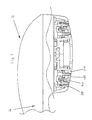
- the shower head 2 is fitted to an extension 4, of which only the end is shown.
- the extension 4 may be part of a handle or a wall fixture.
- Water is guided up the inside of the extension 4 and into the shower head 2.
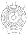
- the shower head 2 of Figures 1 and 2 includes three different arrays 6, 8, 10 of nozzles.
- a mechanism is provided within the shower head 2 to supply selectively the water from the extension 4 into one or more of the arrays 6, 8, 10 of nozzles.
- the internal structure of this particular shower head 2 is also arranged to provide different types of jets of water from the respective arrays of nozzles, in particular fine powerful jets from array 6, aerated jets from array 8 and normal or pulsating jets from array 10.
- a bezel 12 is also provided around the face plate 14 in which the nozzles are formed.
- the internal mechanism is operated so as to change between the various spray patterns and provide water selectively to one or more of the arrays 6,8,10.
- the outer array 6 of nozzles includes a series of nozzles 16 arranged in accordance with the present invention.
- the nozzle 16 is formed of an elastomeric material and comprises a downstream generally conically shaped portion 16a, an upstream generally cylindrically shaped portion 16b and a flange portion 16c with lip seals 16d.
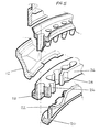
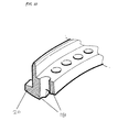
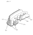
- the nozzle 16 is supported by a first component 18 and a second component 20 which together form part of the face plate 14. These are also illustrated in Figures 4 and 5.
- the first component 18 is connected to the bezel 12.
- the bezel 12 is provided with extensions 12a which fit into corresponding recesses 18a in the first component 18. This rotationally fixes the bezel 12 to the first component 18, such that the bezel 12 may be used to rotate the first component 18.
- the bezel may be attached to the first component 18 in other ways, for instance using adhesive.
- the bezel 12 and first component 18 can be formed as an integral component.
- the advantage of forming them as separate components is that the bezel 12 may then be formed of a different material to that of the first component 18.
- the second component 20 is free to rotate relative to the first component 18. Therefore, when the bezel 12 and first component 18 are rotated, a relative rotation occurs between the first component 18 and second component 20.
- those parts of the first component 18 and the second component 20 which support the downstream portion 16a of the nozzle 16 move relative to one another and shear the downstream portion 16a of the nozzle 16 causing the scale in the downstream portion 16a to be dislodged from the nozzle 16.
- the nozzle 16 is only fixed where it joins the flange portion 16c, the length of the upstream portion 16b gradually absorbs the shearing of the downstream portion 16a as a gradually decreasing twist along its length.
- the flange 16c of the nozzle 16 is provided with two peripheral lip seals 16d. As illustrated in Figure 3, these are used to seal against internal side walls of the shower head 2. In this way, water which is ducted to the nozzles 16 need not at any stage come into contact with the relatively complex arrangement of first and second components 18,20 and bezel 12. In particular, the moving arrangement of the first and second components 18,20 is provided outside of the channelling of the water, such that it is not necessary to provide any water seals in the moving parts.
- downstream portion 16a of the nozzle 16 are conical in shape.
- the divide between the first and second components 16,18 lies substantially along the central axis of this cone.
- consecutive downstream portions 16a will have internal conical sections with axes at different angles.
- three different angles ⁇ for instance -4°, 0°, 4° or 0°, 4°, 8° etc, may be used in sequence around the array of nozzles 16, such that a spread of water jets is formed.
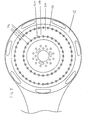
- the internal cross-section may be entirely conical as shown in Figure 3 or only partly conical as shown subsequently in Figures 9 and 12.
- the outer sections of the downstream portion 16a of the nozzle 16 should all be the same, such that all of the supporting areas of the first and second components 18,20 can be of the same shape and dimension and not require the nozzles 16 to be inserted with a particular orientation.
- a shower head is merely provided with an array of nozzles 16 as discussed above without any further array of nozzles.
- the bezel 12 would be used only for cleaning the nozzle 16.
- two further arrays, 8 and 10 are provided and the bezel 12 also functions to operate the mechanism within the shower head 2 to redirect water between the various arrays 6,8,10.
- first component 18 it may be undesirable for the first component 18 to have complete freedom of movement against the second component 20, since a user could over-rotate the first component 18 relative to the second component 20 and thereby damage the nozzle 16. This may be a problem, particularly where the bezel 12 is also used to operate a fairly stiff internal mechanism and where this operation is transmitted through the first and second components 18,20.
- the first and second components 18,20 should be provided with some kind of interlocking arrangement.
- the first and second components 18,20 should be arranged such that only a limited amount of relative rotation is possible.
- the first component 18 once the first component 18 has rotated relative to the second component 20 sufficient to provide the required shear and deformation of the nozzle 16, then it should engage with the second component 20 so as to rotate the second component 20 directly without any further relative rotation.
- Figure 5 illustrates a possible embodiment.
- An outer surface of the second component 20 is formed with a series of outwardly facing teeth 22.
- An inner surface of the first component 18 is formed with a corresponding series of inwardly facing indents 24.
- the indents 24 are slightly bigger than the teeth 22 such that, with the teeth 22 of the second component 20 in the indents 24 of the first component 18, a small amount of relative rotation is possible between the first component 18 and second component 20.
- the relative sizes of the teeth 22 and indents 24 are determined according to the size of the nozzle 16 and the radius of the circle along which they are positioned.
- a nozzle 16 is to be sheared such that the side wall of one half of the nozzle 16 is sheared to a position adjacent the centre of the other half of the nozzle 16. Therefore, the relative sizes of the teeth 22 and indents 24 should be chosen such that a side surface of a tooth 22 engages a corresponding side surface of an indent 24 when the nozzles 16 have been sheared to the extent mentioned above. In this way, any further shearing of the nozzles is prevented and further transmission of forces between the first component 18 and the second component 22 occurs between the side surfaces of the teeth 22 and indents 24, rather than through the nozzles 16.
- teeth 22 and indents 24 allow relative rotation and shearing in both directions.
- the nozzles 16 return to their unsheared and undeformed state.
- an additional sprung mechanism is provided to return the first and second components 18,20 to their aligned state when no relative rotation is imposed by the user. In other words, in its "at rest" state, where a user is not rotating the bezel 12 or first component 18, the first component 18 is forced to a position where its supporting surfaces are aligned with the supporting surfaces of the second component 20 and the nozzles 16 are not deformed.
- Figure 5 illustrates an embodiment including this preferred feature.
- the inner surface of the first component 18 is formed with a resilient cantilevered arm 26 having a return indent 28.
- the return indent 28 is of substantially the same shape and size as the teeth 22.
- the return indent 28 is positioned in the first component 18 such that, in its at rest state when it fully engages a tooth 22, the supporting surfaces of the first component 18 are aligned with the supporting surfaces of the second component 20.
- the return indent 28 and arm 26 In use, when the first component 18 is rotated relative to the second component 20, the return indent 28 and arm 26 is forced outwards by riding up a tooth 22. In this way, when the rotating force is released from the first component 18, the resilient inward force of the arm 26 causes the return indent 28 to ride back down into its engaged position with the tooth 22, thereby causing the first and second components 18,20 to be re-aligned.
- the teeth 22 and indents 24 can have a square section. However, as will be apparent from the above, for the functioning of the return indent 28, the teeth 22 and indents 24,28 should have generally sloped side surfaces.
- the resilient returning force of the cantilever arm 26 should be strong enough to overcome frictional forces to return the first and second components 18,20 to their aligned state, but should not be so great as to prevent relative rotation for the purposes of shearing the nozzles.
- the force required to overcome the cantilever arm 26 should be less than that required to operate the internal mechanism.
- Figure 6 illustrates schematically an alternative return mechanism.
- a generally "M" shaped spring member 30 is formed on the inner surface of the first component 18.
- This spring member 30 can work in one of two ways.
- the respective tooth 22 can cause the spring member 30 to be deflected inwardly as the tooth 22 rotates relative to it.
- the spring member 30 can securely grip the side surfaces of the tooth 22, such that the central portion of the spring member 30 is actually rotated with the tooth 22 relative to the first component 18.
- the spring member 30 acts to return the first component 18 to the position where its supporting surfaces aligned with those of the second component 20.
- the spring member 30 is not formed integrally with the first component 18, but is made of spring steel and is merely fitted to the inner surface of the first component 18.
- Each array of nozzles may be constructed and arranged in the manner described above. However as illustrated more clearly in Figure 9, whereas the third component 18 of the outer array of nozzles 16 is connected to or formed integrally with the bezel 12, the first component 18 of the inner array of nozzles 16 is connected to or formed integrally with the fourth component 20 of the outer array of nozzles.
- Figure 10 illustrates an integral outer fourth component 18 and inner third component 20 of the type previously discussed with reference to Figure 4.
- Figure 11 illustrates an outer fourth component 20 and inner third component 18 corresponding to the first and second components described with reference to Figure 5.
Landscapes
- Nozzles (AREA)
Claims (16)
- Pomme de douche ayant :au moins une première rangée (6) de buses (16) pour produire des jets d'eau respectifs afin de former une configuration de pulvérisation, chaque buse (16) étant constituée d'un matériau résilient souple et s'étendant en continu depuis une portion amont vers une portion aval, caractérisée en ce que :la pomme de douche a aussi, pour au moins la portion aval de chaque buse (16) :un premier composant (18) s'adaptant à une partie de l'étendue périphérique de la surface extérieure de la buse (16) etun second composant (20) s'adaptant sensiblement au reste de l'étendue périphérique de la surface extérieure de la buse (16), de sorte que la portion aval de la buse (16) est sensiblement entièrement supportée,les premier (18) et second (20) composants venant en engagement avec des côtés diamétralement opposés des buses (16) et étant mobiles relativement de façon à cisailler les buses (16).
- Pomme de douche selon la revendication 1 dans laquelle, pour chaque buse (16), le premier composant (18) s'étend le long de la totalité de la longueur de la buse depuis la portion amont vers la portion aval.
- Pomme de douche selon la revendication 2 dans laquelle, sur la portion amont de chaque buse, le premier composant (18) entoure la totalité de l'étendue périphérique de la surface extérieure de la buse (16).
- Pomme de douche selon la revendication 3 dans laquelle une extrémité amont de chaque buse (16) est formée d'un seul tenant avec une bride (16c) qui est montée en amont de et contre une surface intérieure du premier composant (18), la surface intérieure étant sensiblement perpendiculaire à l'étendue de la buse (16) depuis la portion amont vers la portion aval.
- Pomme de douche selon la revendication 3 ou 4 dans laquelle la portion amont de chaque buse (16) est sensiblement cylindrique.
- Pomme de douche selon l'une quelconque des revendications précédentes dans laquelle la portion aval de chaque buse (16) est sensiblement conique.
- Pomme de douche selon l'une quelconque des revendications précédentes comprenant une plaque frontale d'où sortent les jets d'eau et un biseau rotatif (12) autour de la périphérie de la plaque frontale, l'un des premier (18) et second (20) composants étant relié au biseau (12) de façon à provoquer le cisaillement de chaque buse (16) quand le biseau (12) est mis en rotation.
- Pomme de douche selon l'une quelconque des revendications précédentes dans laquelle les premier (18) et second (20) composants sont communs à l'ensemble des buses (16) de ladite première rangée.
- Pomme de douche selon l'une quelconque des revendications précédentes comportant un élément à buses d'un seul tenant comprenant la totalité des buses (16) de ladite première rangée.
- Pomme de douche selon l'une quelconque des revendications précédentes dans laquelle les centres des buses (16) de ladite première rangée sont positionnés sensiblement autour d'un cercle commun.
- Pomme de douche selon l'une quelconque des revendications précédentes dans laquelle les surfaces aval des premier (18) et second (20) composants forment au moins partie de la plaque frontale de la pomme de douche, au-delà de laquelle les buses (16) ne s'étendent pas..
- Pomme de douche selon l'une quelconque des revendications précédentes pour produire plus d'une configuration de pulvérisation et comprenant en outre un élément mobile (12) destiné à permuter entre les configurations de pulvérisation, l'un des premier (18) et second (20) composants étant relié à l'élément mobile (12) de façon à provoquer le cisaillement de chaque buse (16) en permutant entre les configurations de pulvérisation.
- Pomme de douche selon la revendication 12 comprenant en outre au moins une seconde rangée (8, 10) de buses pour produire au moins une autre configuration de pulvérisation.
- Pomme de douche selon l'une quelconque des revendications précédentes ayant au moins une rangée supplémentaire (6) de buses (16) pour produire des jets d'eau respectifs afin de former une configuration de pulvérisation, chaque buse (16) étant composée d'un matériau résilient souple et s'étendant en continu depuis une portion amont vers une portion aval ; la pomme de douche ayant aussi, pour au moins la portion aval de chaque buse (16) : un troisième composant (18) s'adaptant à une partie de l'étendue périphérique de la surface extérieure de la buse (16) et un quatrième composant (20) s'adaptant sensiblement au reste de l'étendue périphérique de la surface extérieure de la buse (16), de sorte que la portion aval de la buse (16) est sensiblement entièrement supportée, les troisième (18) et quatrième (20) composants venant en engagement des côtés diamétralement opposés des buses (16) et étant mobiles relativement de façon à cisailler les buses (16).
- Pomme de douche selon la revendication 14 dans laquelle l'un des premier (18) et second (20) composants de ladite première rangée (6) est formé d'un seul tenant avec l'un des quatrième (20) et troisième (18) composants respectivement de ladite rangée supplémentaire (6).
- Procédé de détartrage des buses d'une pomme de douche ayant des buses (16) composées d'un matériau résilient souple s'étendant en continu depuis une portion amont vers une portion aval, le procédé étant caractérisé par le fait de :prévoir au moins la portion aval de chaque buse (16), un premier composant (18) s'adaptant à une partie de l'étendue périphérique de la surface extérieure de la buse (16) et un second composant (20) s'adaptant sensiblement au reste de l'étendue périphérique de la surface extérieure de la buse (16), de sorte que la portion aval de la buse (16) est sensiblement entièrement supportée etdéplacer relativement les premier (18) et second (20) composants de sorte qu'ils viennent en engagement des côtés diamétralement opposés des buses (16) de façon à cisailler les buses (16).
Applications Claiming Priority (2)
| Application Number | Priority Date | Filing Date | Title |
|---|---|---|---|
| GB9801177A GB2333251B (en) | 1998-01-20 | 1998-01-20 | Shower head |
| GB9801177 | 1998-01-20 |
Publications (3)
| Publication Number | Publication Date |
|---|---|
| EP0930100A2 EP0930100A2 (fr) | 1999-07-21 |
| EP0930100A3 EP0930100A3 (fr) | 2001-01-10 |
| EP0930100B1 true EP0930100B1 (fr) | 2003-06-25 |
Family
ID=10825580
Family Applications (1)
| Application Number | Title | Priority Date | Filing Date |
|---|---|---|---|
| EP98310392A Expired - Lifetime EP0930100B1 (fr) | 1998-01-20 | 1998-12-17 | Pomme de douche |
Country Status (3)
| Country | Link |
|---|---|
| EP (1) | EP0930100B1 (fr) |
| DE (1) | DE69815804T2 (fr) |
| GB (1) | GB2333251B (fr) |
Cited By (1)
| Publication number | Priority date | Publication date | Assignee | Title |
|---|---|---|---|---|
| KR20240171827A (ko) * | 2023-05-31 | 2024-12-09 | 박성호 | 배터리 전원공급 방식의 소화용 가압박스 |
Families Citing this family (5)
| Publication number | Priority date | Publication date | Assignee | Title |
|---|---|---|---|---|
| JP6115761B2 (ja) * | 2013-03-11 | 2017-04-19 | パナソニックIpマネジメント株式会社 | シャワーヘッド |
| DE102016225987A1 (de) * | 2016-12-22 | 2018-06-28 | Hansgrohe Se | Brausestrahlaustrittsvorrichtung und damit ausgerüstete Brause |
| EP3369485B1 (fr) * | 2017-03-01 | 2020-12-16 | Fabrizio Nobili | Pommeau de douche amélioré |
| KR102470192B1 (ko) * | 2020-02-28 | 2022-11-23 | 박성호 | 소화용 가압 박스 |
| CN220573757U (zh) * | 2023-08-10 | 2024-03-12 | 九牧厨卫股份有限公司 | 出液装置及出液系统 |
Family Cites Families (4)
| Publication number | Priority date | Publication date | Assignee | Title |
|---|---|---|---|---|
| DE3044310C2 (de) * | 1980-11-25 | 1984-09-27 | Friedrich Grohe Armaturenfabrik Gmbh & Co, 5870 Hemer | Brauseeinrichtung |
| DE3943062C2 (de) * | 1989-12-28 | 1999-07-15 | Grohe Armaturen Friedrich | Brausekopf |
| DE4308599A1 (de) * | 1992-11-04 | 1994-05-05 | Grohe Armaturen Friedrich | Brausekopf |
| DE4447115C2 (de) * | 1994-12-29 | 1998-11-19 | Hansa Metallwerke Ag | Brausekopf, insbesondere für ein Handbrause |
-
1998
- 1998-01-20 GB GB9801177A patent/GB2333251B/en not_active Expired - Fee Related
- 1998-12-17 EP EP98310392A patent/EP0930100B1/fr not_active Expired - Lifetime
- 1998-12-17 DE DE69815804T patent/DE69815804T2/de not_active Expired - Lifetime
Cited By (1)
| Publication number | Priority date | Publication date | Assignee | Title |
|---|---|---|---|---|
| KR20240171827A (ko) * | 2023-05-31 | 2024-12-09 | 박성호 | 배터리 전원공급 방식의 소화용 가압박스 |
Also Published As
| Publication number | Publication date |
|---|---|
| GB2333251A (en) | 1999-07-21 |
| GB2333251B (en) | 2001-09-12 |
| EP0930100A2 (fr) | 1999-07-21 |
| DE69815804D1 (de) | 2003-07-31 |
| DE69815804T2 (de) | 2004-05-19 |
| EP0930100A3 (fr) | 2001-01-10 |
| GB9801177D0 (en) | 1998-03-18 |
Similar Documents
| Publication | Publication Date | Title |
|---|---|---|
| US5788157A (en) | Shower head | |
| CA2455445C (fr) | Robinet a douchette | |
| US5172862A (en) | Shower head | |
| JP6687589B2 (ja) | シャワージェット吐出器及びこれを備えたシャワー装置 | |
| US5699964A (en) | Showerhead and bottom portion thereof | |
| US5730362A (en) | Shower head with impact protection plate | |
| TW522046B (en) | Showerhead engine assembly and its faceplate | |
| US5730363A (en) | Shower head | |
| EP0566723B1 (fr) | Ajutage de pomme de douche | |
| EP3974063B1 (fr) | Mécanisme de détartrage de dispositif de sortie de liquide, dispositif de sortie de liquide, douche et robinet | |
| CA2603769A1 (fr) | Pulverisateur a col flexible pour robinet | |
| JP2022553466A (ja) | 側面切替レバーを備えた自動復帰型シャワーヘッド及びシャワー装置 | |
| CN116474965B (zh) | 一种水流整形器 | |
| EP0861127A1 (fr) | Procede de fabrication de diffuseurs pour tetes de douche | |
| EP0930100A2 (fr) | Pomme de douche | |
| JP2021535785A (ja) | 拭き部材、拭き装置、掃除ロボット及び掃除ロボットの制御方法 | |
| US20260061449A1 (en) | Water outlet device | |
| CN108742909B (zh) | 一种洗牙器用喷嘴以及洗牙器 | |
| JP5529452B2 (ja) | シャワーヘッド | |
| JP2011025132A (ja) | シャワーヘッド | |
| CN215843654U (zh) | 一种多功能出水的花洒插座组合装置 | |
| JP2004322066A (ja) | エッチング加工した金属薄板 | |
| CN216535597U (zh) | 散流型冲牙器喷嘴 | |
| CN119076249B (zh) | 一种出水装置 | |
| US20250341080A1 (en) | Water outlet structure |
Legal Events
| Date | Code | Title | Description |
|---|---|---|---|
| PUAI | Public reference made under article 153(3) epc to a published international application that has entered the european phase |
Free format text: ORIGINAL CODE: 0009012 |
|
| AK | Designated contracting states |
Kind code of ref document: A2 Designated state(s): DE FR GB |
|
| AX | Request for extension of the european patent |
Free format text: AL;LT;LV;MK;RO;SI |
|
| PUAL | Search report despatched |
Free format text: ORIGINAL CODE: 0009013 |
|
| AK | Designated contracting states |
Kind code of ref document: A3 Designated state(s): AT BE CH CY DE DK ES FI FR GB GR IE IT LI LU MC NL PT SE |
|
| AX | Request for extension of the european patent |
Free format text: AL;LT;LV;MK;RO;SI |
|
| RIC1 | Information provided on ipc code assigned before grant |
Free format text: 7B 05B 1/18 A, 7B 05B 15/02 B |
|
| 17P | Request for examination filed |
Effective date: 20010215 |
|
| AKX | Designation fees paid |
Free format text: DE FR GB |
|
| 17Q | First examination report despatched |
Effective date: 20020402 |
|
| GRAH | Despatch of communication of intention to grant a patent |
Free format text: ORIGINAL CODE: EPIDOS IGRA |
|
| GRAH | Despatch of communication of intention to grant a patent |
Free format text: ORIGINAL CODE: EPIDOS IGRA |
|
| GRAA | (expected) grant |
Free format text: ORIGINAL CODE: 0009210 |
|
| AK | Designated contracting states |
Designated state(s): DE FR GB |
|
| REG | Reference to a national code |
Ref country code: GB Ref legal event code: FG4D |
|
| REF | Corresponds to: |
Ref document number: 69815804 Country of ref document: DE Date of ref document: 20030731 Kind code of ref document: P |
|
| ET | Fr: translation filed | ||
| PLBE | No opposition filed within time limit |
Free format text: ORIGINAL CODE: 0009261 |
|
| STAA | Information on the status of an ep patent application or granted ep patent |
Free format text: STATUS: NO OPPOSITION FILED WITHIN TIME LIMIT |
|
| REG | Reference to a national code |
Ref country code: GB Ref legal event code: 732E |
|
| 26N | No opposition filed |
Effective date: 20040326 |
|
| REG | Reference to a national code |
Ref country code: GB Ref legal event code: 732E Free format text: REGISTERED BETWEEN 20120301 AND 20120307 |
|
| REG | Reference to a national code |
Ref country code: GB Ref legal event code: 732E Free format text: REGISTERED BETWEEN 20151001 AND 20151007 |
|
| REG | Reference to a national code |
Ref country code: FR Ref legal event code: PLFP Year of fee payment: 18 |
|
| REG | Reference to a national code |
Ref country code: FR Ref legal event code: PLFP Year of fee payment: 19 |
|
| PGFP | Annual fee paid to national office [announced via postgrant information from national office to epo] |
Ref country code: DE Payment date: 20170110 Year of fee payment: 19 Ref country code: FR Payment date: 20170113 Year of fee payment: 19 |
|
| PGFP | Annual fee paid to national office [announced via postgrant information from national office to epo] |
Ref country code: GB Payment date: 20170106 Year of fee payment: 19 |
|
| REG | Reference to a national code |
Ref country code: DE Ref legal event code: R119 Ref document number: 69815804 Country of ref document: DE |
|
| GBPC | Gb: european patent ceased through non-payment of renewal fee |
Effective date: 20171217 |
|
| REG | Reference to a national code |
Ref country code: FR Ref legal event code: ST Effective date: 20180831 |
|
| PG25 | Lapsed in a contracting state [announced via postgrant information from national office to epo] |
Ref country code: DE Free format text: LAPSE BECAUSE OF NON-PAYMENT OF DUE FEES Effective date: 20180703 Ref country code: FR Free format text: LAPSE BECAUSE OF NON-PAYMENT OF DUE FEES Effective date: 20180102 |
|
| PG25 | Lapsed in a contracting state [announced via postgrant information from national office to epo] |
Ref country code: GB Free format text: LAPSE BECAUSE OF NON-PAYMENT OF DUE FEES Effective date: 20171217 |