EP0930108A2 - Dispositif de dépot de boucles de fil - Google Patents
Dispositif de dépot de boucles de fil Download PDFInfo
- Publication number
- EP0930108A2 EP0930108A2 EP99100480A EP99100480A EP0930108A2 EP 0930108 A2 EP0930108 A2 EP 0930108A2 EP 99100480 A EP99100480 A EP 99100480A EP 99100480 A EP99100480 A EP 99100480A EP 0930108 A2 EP0930108 A2 EP 0930108A2
- Authority
- EP
- European Patent Office
- Prior art keywords
- wire
- scissors
- cutting
- conveyor belt
- depositing
- Prior art date
- Legal status (The legal status is an assumption and is not a legal conclusion. Google has not performed a legal analysis and makes no representation as to the accuracy of the status listed.)
- Granted
Links
Images


Classifications
-
- B—PERFORMING OPERATIONS; TRANSPORTING
- B21—MECHANICAL METAL-WORKING WITHOUT ESSENTIALLY REMOVING MATERIAL; PUNCHING METAL
- B21C—MANUFACTURE OF METAL SHEETS, WIRE, RODS, TUBES, PROFILES OR LIKE SEMI-MANUFACTURED PRODUCTS OTHERWISE THAN BY ROLLING; AUXILIARY OPERATIONS USED IN CONNECTION WITH METAL-WORKING WITHOUT ESSENTIALLY REMOVING MATERIAL
- B21C47/00—Winding-up, coiling or winding-off metal wire, metal band or other flexible metal material characterised by features relevant to metal processing only
- B21C47/26—Special arrangements with regard to simultaneous or subsequent treatment of the material
-
- B—PERFORMING OPERATIONS; TRANSPORTING
- B21—MECHANICAL METAL-WORKING WITHOUT ESSENTIALLY REMOVING MATERIAL; PUNCHING METAL
- B21C—MANUFACTURE OF METAL SHEETS, WIRE, RODS, TUBES, PROFILES OR LIKE SEMI-MANUFACTURED PRODUCTS OTHERWISE THAN BY ROLLING; AUXILIARY OPERATIONS USED IN CONNECTION WITH METAL-WORKING WITHOUT ESSENTIALLY REMOVING MATERIAL
- B21C47/00—Winding-up, coiling or winding-off metal wire, metal band or other flexible metal material characterised by features relevant to metal processing only
- B21C47/02—Winding-up or coiling
- B21C47/10—Winding-up or coiling by means of a moving guide
- B21C47/14—Winding-up or coiling by means of a moving guide by means of a rotating guide, e.g. laying the material around a stationary reel or drum
- B21C47/143—Winding-up or coiling by means of a moving guide by means of a rotating guide, e.g. laying the material around a stationary reel or drum the guide being a tube
-
- B—PERFORMING OPERATIONS; TRANSPORTING
- B21—MECHANICAL METAL-WORKING WITHOUT ESSENTIALLY REMOVING MATERIAL; PUNCHING METAL
- B21C—MANUFACTURE OF METAL SHEETS, WIRE, RODS, TUBES, PROFILES OR LIKE SEMI-MANUFACTURED PRODUCTS OTHERWISE THAN BY ROLLING; AUXILIARY OPERATIONS USED IN CONNECTION WITH METAL-WORKING WITHOUT ESSENTIALLY REMOVING MATERIAL
- B21C47/00—Winding-up, coiling or winding-off metal wire, metal band or other flexible metal material characterised by features relevant to metal processing only
- B21C47/02—Winding-up or coiling
- B21C47/10—Winding-up or coiling by means of a moving guide
- B21C47/14—Winding-up or coiling by means of a moving guide by means of a rotating guide, e.g. laying the material around a stationary reel or drum
- B21C47/146—Controlling or influencing the laying pattern of the coils
Definitions
- the present invention relates to a storage device for Laying turns of wire with a wire axis on one Conveyor belt, in particular a Stelmor conveyor belt, with a rotating coiler with an outlet opening out of it the turns in a depositing direction at a depositing speed be delivered to the conveyor belt.
- Such a depositing device is, for example, from EP 0 432 531 A1 known.
- the object of the present invention is a storage device to create the disadvantages of the prior art Technology eliminated.
- the winding layer has a pair of scissors with a fixed and a knife drive in one Cutting direction with a cutting speed movable knife is connected downstream and that the movable knife a separating plate to separate the turns on the turntable side from the Good turns on the conveyor belt side is assigned.
- the cutting direction with the laying direction is 90 ° forms different angles, so that the cutting speed component parallel to the depositing direction, and the cutting speed and the laying speed on each other are coordinated that the component parallel to the laying direction the cutting speed is approximately equal to the laying speed the wire is only removed from the separating plate shortly before the cut begins touched. The good turns are therefore not deformed.
- the movable knife and the separating plate can be linear Carry out movement.
- the construction is special easy when they do a rotary motion.
- the wire will be cut in the right place if that Windungsleger a wire detection sensor for detecting the wire end is connected upstream and the detection of the wire end by the wire detection sensor triggers the operation of the scissors.
- the last turns still fed to the conveyor belt are especially safe not deformed when the wire is like this is cut that seen from the scissors conveyor belt side Cutting end of the wire pulling on the conveyor belt is promoted.
- Such a cut can in particular achieved that the winding layer an angle detection sensor is assigned and the scissors are released when the Winding layer reaches a predetermined angle of rotation.
- the operation of the scissors is particularly fail-safe.
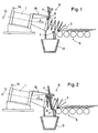
- a depositing device for depositing windings made of wire has a rotating winding layer 1.
- the winding layer 1 has an outlet opening 2 from which a wire 3 is delivered in turns in a depositing direction 4 to a conveyor belt 5 at a depositing speed v A.
- the depositing speed v A is the speed at which the wire windings move along their winding axis.
- the conveyor belt 5 is designed in the present case as a so-called Stelmor conveyor belt 5.
- a pair of scissors 6 is connected downstream of the winding layer 1.
- the scissors 6 have a fixed knife 7 and a movable knife 8.
- the scissors 6 is driven by a knife drive 9 and cuts the wire 3 in a cutting direction 10 at a cutting speed v S.
- the cutting direction 10 forms an angle ⁇ with the depositing direction 4 which is different from 90 °.
- the cutting speed v S therefore has a component v SA parallel to the laying direction.
- the cutting speed v S and the depositing speed v A are coordinated with one another in such a way that the component v SA of the cutting speed v S parallel to the depositing direction 4 is between 75 and 125%, preferably between 90 and 110%, of the depositing speed v A.
- the knife drive 9 is in the present case as an electric motor educated. But it could also be used as a hydraulic motor, as a hydraulic cylinder unit or be designed as a pneumatic cylinder unit.
- the movable knife 8 is for separating the winding layer 1 from Conveyor belt 5 is assigned a separating plate 11.
- the separating plate 11 is designed as a plate that is substantially parallel extends to the cutting direction 10.
- a wire detection sensor 12 is connected upstream of the winding layer 1.
- the wire detection sensor 12 detects the end of the wire 3 recorded, which then - possibly via a timer - the Operating the scissors 6 triggers.
- the wire detection sensor 12 can be designed as a photocell, for example.
- the movable knife 8 together with the separating plate 11 is accelerated by the knife drive 9 from the initial position shown in FIG. 3 to the cutting speed v S. Then the wire 3 is cut in the position shown in FIG. 4 and then the movable knife 8 is braked together with the separating plate 11. The movable knife 8 and the separating plate 11 then come to a standstill in the position shown in broken lines in FIG. 4. They are then rotated back into the position shown in FIG. 3 in order to be prepared for the next cut.
- the transport of the turns of the wire 3 on the conveyor belt 5 is particularly fail-safe if the wire 3 is cut in this way is that seen from the scissors 6 conveyor belt side Cutting end 13 of the wire 3 is pulled on the conveyor belt 5 becomes.
- Such a section is shown by way of example in FIG. 7.
- Such a cut can be achieved in that the winding layer 1, an angle detection sensor 14 is assigned by means of the angular position of the outlet opening 2 can be detected.
- the scissors 6 are only triggered when the Winding layer 1 or the outlet opening 2 a predetermined Reach angle of rotation.
- the angle of rotation is a matter of course only modulo 2 ⁇ determined.
- the angle of rotation as such is arbitrary selectable since the start of the acceleration of the movable knife 8 can optionally be delayed by a timer. It is crucial that at the beginning of the acceleration process the Winding layer 1 reaches a defined angular position.
- the angle detection sensor can be designed, for example, as a magnetic sensor which is triggered by an iron plate, which together with the Coil layer rotates.
- the fixed knife 7 and the movable knife 8 are according to the embodiment arranged at an angle to the plane denoted by 16. This ensures that the scissors 6 along the wire 3 an intersection that intersects an intersection angle with the wire axis of at least 45 °.
- the cutting angle is preferred greater than 45 °, e.g. at least 60 °.
- a wire shredder Around the cut end turns of the wire 3 slightly To be able to handle is between the scissors 6 and the collecting container 17 a wire shredder, not shown, is arranged.
- the Wire shredder can be used, for example, as a chopper with a known design helical knives.
- FIG. 8 now shows the structural design of the winding layer 1 and the scissors 6.
- the fixed knife 7 is attached to a base frame 18.
- the movable knife 8 is held by the separating plate 11, which is mounted on a shaft 19 in a housing 20.
- the Shaft 19 is via a clutch 21 and a gear 22 with the Knife drive 9 connected.
- the protective hood 15 covers the actual one Turn layer 1 from.
Landscapes
- Engineering & Computer Science (AREA)
- Mechanical Engineering (AREA)
- Winding, Rewinding, Material Storage Devices (AREA)
- Coiling Of Filamentary Materials In General (AREA)
- Wire Processing (AREA)
- Metal Extraction Processes (AREA)
- Electrical Discharge Machining, Electrochemical Machining, And Combined Machining (AREA)
- Coating With Molten Metal (AREA)
Applications Claiming Priority (2)
| Application Number | Priority Date | Filing Date | Title |
|---|---|---|---|
| DE19801406A DE19801406A1 (de) | 1998-01-16 | 1998-01-16 | Ablegevorrichtung zum Ablegen von Windungen aus Draht |
| DE19801406 | 1998-01-16 |
Publications (3)
| Publication Number | Publication Date |
|---|---|
| EP0930108A2 true EP0930108A2 (fr) | 1999-07-21 |
| EP0930108A3 EP0930108A3 (fr) | 2001-01-24 |
| EP0930108B1 EP0930108B1 (fr) | 2003-03-12 |
Family
ID=7854768
Family Applications (1)
| Application Number | Title | Priority Date | Filing Date |
|---|---|---|---|
| EP99100480A Expired - Lifetime EP0930108B1 (fr) | 1998-01-16 | 1999-01-12 | Dispositif de dépot de boucles de fil |
Country Status (3)
| Country | Link |
|---|---|
| EP (1) | EP0930108B1 (fr) |
| AT (1) | ATE234169T1 (fr) |
| DE (2) | DE19801406A1 (fr) |
Cited By (3)
| Publication number | Priority date | Publication date | Assignee | Title |
|---|---|---|---|---|
| CN104841812A (zh) * | 2015-03-24 | 2015-08-19 | 昆山德友机械设备有限公司 | 一种切割金属线的设备 |
| CN105109893A (zh) * | 2015-09-15 | 2015-12-02 | 浙江乔兴建设集团湖州智能科技有限公司 | 一种金属切断机的金属丝段输送装置 |
| CN105217219A (zh) * | 2015-09-21 | 2016-01-06 | 芜湖顺成电子有限公司 | 电线切断收料装置 |
Family Cites Families (3)
| Publication number | Priority date | Publication date | Assignee | Title |
|---|---|---|---|---|
| DD125644A1 (fr) * | 1976-01-15 | 1977-05-11 | ||
| DD228465A1 (de) * | 1984-11-06 | 1985-10-16 | Thaelmann Schwermaschbau Veb | Verfahren und vorrichtung zum kontrollierten abkuehlen von walzdraht |
| DE3940735A1 (de) * | 1989-12-09 | 1991-06-13 | Schloemann Siemag Ag | Kuehleinrichtung fuer walzdraht |
-
1998
- 1998-01-16 DE DE19801406A patent/DE19801406A1/de not_active Withdrawn
-
1999
- 1999-01-12 AT AT99100480T patent/ATE234169T1/de not_active IP Right Cessation
- 1999-01-12 DE DE59904507T patent/DE59904507D1/de not_active Expired - Fee Related
- 1999-01-12 EP EP99100480A patent/EP0930108B1/fr not_active Expired - Lifetime
Cited By (5)
| Publication number | Priority date | Publication date | Assignee | Title |
|---|---|---|---|---|
| CN104841812A (zh) * | 2015-03-24 | 2015-08-19 | 昆山德友机械设备有限公司 | 一种切割金属线的设备 |
| CN104841812B (zh) * | 2015-03-24 | 2017-01-11 | 昆山德友机械设备有限公司 | 一种切割金属线的设备 |
| CN105109893A (zh) * | 2015-09-15 | 2015-12-02 | 浙江乔兴建设集团湖州智能科技有限公司 | 一种金属切断机的金属丝段输送装置 |
| CN105109893B (zh) * | 2015-09-15 | 2017-06-30 | 乐清市华尊电气有限公司 | 一种金属切断机的金属丝段输送装置 |
| CN105217219A (zh) * | 2015-09-21 | 2016-01-06 | 芜湖顺成电子有限公司 | 电线切断收料装置 |
Also Published As
| Publication number | Publication date |
|---|---|
| EP0930108B1 (fr) | 2003-03-12 |
| ATE234169T1 (de) | 2003-03-15 |
| DE19801406A1 (de) | 1999-07-22 |
| DE59904507D1 (de) | 2003-04-17 |
| EP0930108A3 (fr) | 2001-01-24 |
Similar Documents
| Publication | Publication Date | Title |
|---|---|---|
| DE2121426A1 (de) | Verfahren und Vorrichtung zum Abnehmen aufgespulter Wickel und Aufsetzen leerer Wickelkerne | |
| DE2361001C2 (de) | Vorrichtung zum Abschneiden eines Stranges | |
| DE4318299A1 (de) | Einziehvorrichtung und Verfahren zum Einzug von Materialbahnen in eine Druckmaschine | |
| DE10020968A1 (de) | Kupplungslose Drahtschneideinrichtung | |
| DE2547301C2 (fr) | ||
| DE2100088B2 (de) | Haspelofen für ein kontinuierliches Feineisenwalzwerk | |
| DE3630744C2 (de) | Kontinuierlich arbeitende Umrollvorrichtung mit einer Andrückwalze | |
| EP0930108B1 (fr) | Dispositif de dépot de boucles de fil | |
| EP1026113A2 (fr) | Distributeur de film | |
| EP0036410B1 (fr) | Installation pour le traitement de fil tel que décalaminage, estampage ou étirage et dressage subséquent | |
| DE2917305C2 (de) | Verfahren zur Beseitigung des Vorder- und Hinterabschnitts von Walzdraht und Vorrichtung zur Durchführung des Verfahrens | |
| DE2915716C2 (de) | Verfahren zur Beseitigung des Vorder- und Hinterabschnitts von Walzdraht und Vorrichtung zur Durchführung des Verfahrens | |
| DE602005005483T2 (de) | Vorrichtung zur Änderung der Geschwindigkeit von Stangen | |
| DE102009039825B4 (de) | Schneidmaschine | |
| EP0027106B1 (fr) | Dispositif pour amener automatiquement du matériau en tiges à une machine à cintrer des brides d'armature de béton | |
| DE4310675A1 (de) | Papierrolle, Papierrollenauspackstation zum Auspacken der Papierrolle und Verfahren zum Auspacken der Papierrolle | |
| DE2635235C2 (de) | Vorrichtung zum Abführen und Zerkleinern der in einer Trenneinrichtung abgetrennten Schopfenden von Walzgutsträngen | |
| DE2539697C2 (de) | Gießwalzanlage für Draht | |
| DE3641892C2 (fr) | ||
| DE19817035A1 (de) | Vorrichtung zum Schneiden von Drahtwindungen | |
| DE2940761C2 (de) | Vorrichtung zum seitlichen Auswerfen von langgestrecktem Gut | |
| DE2649340A1 (de) | Haspel zum kompakten aufwickeln von draht | |
| DE1527867B2 (de) | Wahlweise im edenborn oder garrett system arbeitender haspel fuer walzdraht | |
| DE4218962A1 (de) | Drahtabschneidvorrichtung | |
| DE1967064A1 (de) | Vorrichtung zum kontinuierlichen aufwickeln drahtfoermigen gutes |
Legal Events
| Date | Code | Title | Description |
|---|---|---|---|
| PUAI | Public reference made under article 153(3) epc to a published international application that has entered the european phase |
Free format text: ORIGINAL CODE: 0009012 |
|
| 17P | Request for examination filed |
Effective date: 19990112 |
|
| AK | Designated contracting states |
Kind code of ref document: A2 Designated state(s): AT DE ES FR GB IT LU |
|
| AX | Request for extension of the european patent |
Free format text: AL;LT;LV;MK;RO;SI |
|
| RAP1 | Party data changed (applicant data changed or rights of an application transferred) |
Owner name: SMS DEMAG AG |
|
| PUAL | Search report despatched |
Free format text: ORIGINAL CODE: 0009013 |
|
| AK | Designated contracting states |
Kind code of ref document: A3 Designated state(s): AT BE CH CY DE DK ES FI FR GB GR IE IT LI LU MC NL PT SE |
|
| AX | Request for extension of the european patent |
Free format text: AL;LT;LV;MK;RO;SI |
|
| AKX | Designation fees paid |
Free format text: AT DE ES FR GB IT LU |
|
| 17Q | First examination report despatched |
Effective date: 20020115 |
|
| GRAH | Despatch of communication of intention to grant a patent |
Free format text: ORIGINAL CODE: EPIDOS IGRA |
|
| GRAH | Despatch of communication of intention to grant a patent |
Free format text: ORIGINAL CODE: EPIDOS IGRA |
|
| GRAA | (expected) grant |
Free format text: ORIGINAL CODE: 0009210 |
|
| AK | Designated contracting states |
Designated state(s): AT DE ES FR GB IT LU |
|
| PG25 | Lapsed in a contracting state [announced via postgrant information from national office to epo] |
Ref country code: FR Free format text: LAPSE BECAUSE OF FAILURE TO SUBMIT A TRANSLATION OF THE DESCRIPTION OR TO PAY THE FEE WITHIN THE PRESCRIBED TIME-LIMIT Effective date: 20030312 |
|
| REG | Reference to a national code |
Ref country code: GB Ref legal event code: FG4D Free format text: NOT ENGLISH |
|
| REF | Corresponds to: |
Ref document number: 59904507 Country of ref document: DE Date of ref document: 20030417 Kind code of ref document: P |
|
| GBT | Gb: translation of ep patent filed (gb section 77(6)(a)/1977) | ||
| PG25 | Lapsed in a contracting state [announced via postgrant information from national office to epo] |
Ref country code: ES Free format text: LAPSE BECAUSE OF FAILURE TO SUBMIT A TRANSLATION OF THE DESCRIPTION OR TO PAY THE FEE WITHIN THE PRESCRIBED TIME-LIMIT Effective date: 20030930 |
|
| PG25 | Lapsed in a contracting state [announced via postgrant information from national office to epo] |
Ref country code: LU Free format text: LAPSE BECAUSE OF NON-PAYMENT OF DUE FEES Effective date: 20040112 |
|
| PLBE | No opposition filed within time limit |
Free format text: ORIGINAL CODE: 0009261 |
|
| STAA | Information on the status of an ep patent application or granted ep patent |
Free format text: STATUS: NO OPPOSITION FILED WITHIN TIME LIMIT |
|
| EN | Fr: translation not filed | ||
| 26N | No opposition filed |
Effective date: 20031215 |
|
| PGFP | Annual fee paid to national office [announced via postgrant information from national office to epo] |
Ref country code: DE Payment date: 20060112 Year of fee payment: 8 |
|
| PGFP | Annual fee paid to national office [announced via postgrant information from national office to epo] |
Ref country code: AT Payment date: 20060113 Year of fee payment: 8 |
|
| PGFP | Annual fee paid to national office [announced via postgrant information from national office to epo] |
Ref country code: IT Payment date: 20060131 Year of fee payment: 8 |
|
| PG25 | Lapsed in a contracting state [announced via postgrant information from national office to epo] |
Ref country code: DE Free format text: LAPSE BECAUSE OF NON-PAYMENT OF DUE FEES Effective date: 20070801 |
|
| GBPC | Gb: european patent ceased through non-payment of renewal fee |
Effective date: 20070112 |
|
| PG25 | Lapsed in a contracting state [announced via postgrant information from national office to epo] |
Ref country code: GB Free format text: LAPSE BECAUSE OF NON-PAYMENT OF DUE FEES Effective date: 20070112 Ref country code: AT Free format text: LAPSE BECAUSE OF NON-PAYMENT OF DUE FEES Effective date: 20070112 |
|
| PGFP | Annual fee paid to national office [announced via postgrant information from national office to epo] |
Ref country code: GB Payment date: 20060120 Year of fee payment: 8 |
|
| PG25 | Lapsed in a contracting state [announced via postgrant information from national office to epo] |
Ref country code: IT Free format text: LAPSE BECAUSE OF NON-PAYMENT OF DUE FEES Effective date: 20070112 |