EP0930130A2 - Dispositif de serrage - Google Patents
Dispositif de serrage Download PDFInfo
- Publication number
- EP0930130A2 EP0930130A2 EP99100659A EP99100659A EP0930130A2 EP 0930130 A2 EP0930130 A2 EP 0930130A2 EP 99100659 A EP99100659 A EP 99100659A EP 99100659 A EP99100659 A EP 99100659A EP 0930130 A2 EP0930130 A2 EP 0930130A2
- Authority
- EP
- European Patent Office
- Prior art keywords
- actuator
- clamping device
- module
- pressure medium
- connections
- Prior art date
- Legal status (The legal status is an assumption and is not a legal conclusion. Google has not performed a legal analysis and makes no representation as to the accuracy of the status listed.)
- Granted
Links
Images


Classifications
-
- B—PERFORMING OPERATIONS; TRANSPORTING
- B25—HAND TOOLS; PORTABLE POWER-DRIVEN TOOLS; MANIPULATORS
- B25B—TOOLS OR BENCH DEVICES NOT OTHERWISE PROVIDED FOR, FOR FASTENING, CONNECTING, DISENGAGING, OR HOLDING
- B25B5/00—Clamps
- B25B5/06—Arrangements for positively actuating jaws
- B25B5/061—Arrangements for positively actuating jaws with fluid drive
-
- B—PERFORMING OPERATIONS; TRANSPORTING
- B25—HAND TOOLS; PORTABLE POWER-DRIVEN TOOLS; MANIPULATORS
- B25B—TOOLS OR BENCH DEVICES NOT OTHERWISE PROVIDED FOR, FOR FASTENING, CONNECTING, DISENGAGING, OR HOLDING
- B25B5/00—Clamps
- B25B5/06—Arrangements for positively actuating jaws
- B25B5/12—Arrangements for positively actuating jaws using toggle links
- B25B5/122—Arrangements for positively actuating jaws using toggle links with fluid drive
-
- B—PERFORMING OPERATIONS; TRANSPORTING
- B25—HAND TOOLS; PORTABLE POWER-DRIVEN TOOLS; MANIPULATORS
- B25B—TOOLS OR BENCH DEVICES NOT OTHERWISE PROVIDED FOR, FOR FASTENING, CONNECTING, DISENGAGING, OR HOLDING
- B25B5/00—Clamps
- B25B5/16—Details, e.g. jaws, jaw attachments
-
- F—MECHANICAL ENGINEERING; LIGHTING; HEATING; WEAPONS; BLASTING
- F15—FLUID-PRESSURE ACTUATORS; HYDRAULICS OR PNEUMATICS IN GENERAL
- F15B—SYSTEMS ACTING BY MEANS OF FLUIDS IN GENERAL; FLUID-PRESSURE ACTUATORS, e.g. SERVOMOTORS; DETAILS OF FLUID-PRESSURE SYSTEMS, NOT OTHERWISE PROVIDED FOR
- F15B15/00—Fluid-actuated devices for displacing a member from one position to another; Gearing associated therewith
- F15B15/20—Other details, e.g. assembly with regulating devices
- F15B15/202—Externally-operated valves mounted in or on the actuator
-
- F—MECHANICAL ENGINEERING; LIGHTING; HEATING; WEAPONS; BLASTING
- F15—FLUID-PRESSURE ACTUATORS; HYDRAULICS OR PNEUMATICS IN GENERAL
- F15B—SYSTEMS ACTING BY MEANS OF FLUIDS IN GENERAL; FLUID-PRESSURE ACTUATORS, e.g. SERVOMOTORS; DETAILS OF FLUID-PRESSURE SYSTEMS, NOT OTHERWISE PROVIDED FOR
- F15B15/00—Fluid-actuated devices for displacing a member from one position to another; Gearing associated therewith
- F15B15/20—Other details, e.g. assembly with regulating devices
- F15B15/28—Means for indicating the position, e.g. end of stroke
- F15B15/2807—Position switches, i.e. means for sensing of discrete positions only, e.g. limit switches
Definitions
- the invention relates to a clamping device for clamping of workpieces according to the preamble of the claim 1.
- Such a tensioning device is, for example, according to DE-U-87 14 390.9 known.
- This tensioning device consists, as in essentially all other comparable clamping devices also, from a pressure medium operated actuator with a so-called interface for pressure and Electrical connections, the actuator being linear movable actuator and one in the head of the clamping device arranged adjusting mechanism with a swivel mounted tension arm is connected and the actuator a position interrogation device with electrical position interrogation connections assigned.
- the so-called Interface is from the bottom cover of the Actuator or the actuating cylinder formed.
- Such clamping devices are in the majority of cases not alone, but at the same time in the so-called System group with several other similar or also operated different clamping devices.
- the tensioning devices usually have different functions to perform and equipped and controlled accordingly have to be.
- the invention has for its object a tensioning device of the type mentioned at the outset to improve that they have different connection and functional requirements is easily customizable, this In other words, of the same type, but functionally adapted to different ones Functional points of an entire system for use can come.
- connection module is also advantageous the electrical position query connections included. To ensure that the head of the jig arranged position interrogation device to the connection module electrical cables are not damaged, it is also advantageous to have a connection module on the actuator to be arranged as a cable guide.
- connection module electronic microprocessor Means for sending and receiving coded information signals to arrange. So, for example, has a certain one Clamping device reached one of its two end positions and should this information to the control or regulating device forwarded, so will the corresponding Signal coded in this way using the electronic means and transferred to the common control line that corresponding electronic means of the control and regulating device after decoding are able to do this To convey information of the respective clamping device.
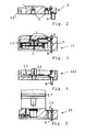
- connection module in principle, two different connection modules are provided, namely a connection module in the form of an end piece, which can also be connected alone at the interface, and a connection module in the form of an intermediate piece, which is located between the actuator and the end piece, wherein, as will be explained in more detail, several intermediate pieces can be provided. Furthermore, a connection module is also provided, which can be used both as an end piece and as an intermediate piece. With regard to the function of the individual connection modules, reference is made to the following description of the exemplary embodiments.
- the clamping device is shown in section, which in a known manner from a pressure medium operated actuator provided with pressure medium connections 2 1 (pneumatic or hydraulic cylinder), which has a linearly moving actuator 3 and one in the head 4 of the Adjusting mechanism 5 arranged with a clamping device pivotally mounted tension arm 6 is connected, wherein the actuator 3 a position request device indicated only schematically 7 with electrical position sensing connections 8 (overall only as a socket connection shown) is assigned.
- the so-called interface here is designated 9.
- Actuator 1 a pressure medium channel 10 in the embodiments provided according to Figures 1 and 6 to 15.
- connection module V is on the actuator 1 Cable routing for the electrical connection between the Position interrogation device 7 and the respective the lower Cover closure of the actuator forming module arranged.
- connection modules I-IV to be used both as end pieces and as intermediate pieces, the module according to FIG. 2 corresponding to connection module I according to FIG. 1.
- the intermediate piece or module II according to FIG. 3 has an electrically controlled directional valve 16 for opening and closing the pressure medium connections 2, its electrical connections 17 for controlling the directional valve 16 being connected to the query connections 8 of the interface 9.
- the terminal module III in FIG. 4 in the form of an end piece, contains a microprocessor 12 comprising electronic means 13 (circuit board) for transmitting and receiving coded information signals which are connected to a control device (not shown) of other clamping devices.
- This module according to FIG. 4 is of particular interest for those cases in which several clamping devices are to be functionally interconnected as a kind of computer network.
- Fig. 5 is finally as a cushioning 15 for the piston 1 "of the actuator 1 serving module IV shown. This is known end position damping 15 Required especially for quick-opening clamping devices to "break through" the actuator base to avoid.
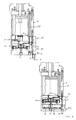
- 6 to 10 are the aforementioned modules I to IV presented in different arrangement and assignment options, to be achieved by the training according to the invention Variability and adaptability of the clamping device to different connection and function requirements to clarify.
- connection module I with Has pressure medium connections 2.
- the electrical position sensing connections 8 (only as a small socket ) to the connection module mentioned above V save, in the immediate vicinity of the position interrogation device 7 as a separate, laterally attached module 11 arranged.
- FIG. 12 corresponds to that in FIG. 11, but supplemented by module IV for the end position damping.
- FIG. 13 also shows a tensioning device with a multi-way valve 16 with its own electrical connections 17, which, however, can also be provided in a separate, externally attached module 11 '.
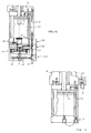
- FIGS. 14 and 15 show clamping devices in which the electronic means 13 having a microprocessor 12 are also arranged in the aforementioned connection module V '.
- the connection module I 'serving as an extension corresponds functionally to module I.
- This connection module I' can, however, as mentioned above, be used both as an intermediate piece and as an end piece.
- modules with which, for example installed position sensors all angular positions of the clamping arm 6 can be processed or if it is clamping devices that except with their Pressure medium actuator can also be adjusted using the hand lever can, i.e. modules that are intended for manual operation make sure that this actually works can be.
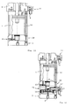
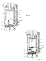
- the axially oriented extension is of the modules at the lower end of the actuator 1 (apart from of the possibly required damping module IV) is not mandatory, i.e. the assignment of the modules can also be done directly in parallel next to the actuator, such as this. is illustrated in Fig. 16. For such an assignment is essential that parallel to the axis 1 'of the actuator 1st also functionally different, mutually compatible Connection modules are arranged, the interface 9 for the pressure medium connections of the actuator 1 to the module arrangement side is oriented towards.
- a pressure medium guide channel 10 ' is provided for the tension arm reset, ie the pressure medium connection for the tension arm or piston reset is located at the upper end 20 of the actuator 1, an adapter 21 is provided which contains corresponding pressure medium guide channels 10', which are functionally connected to the attached valve module II '.
- This valve module II ' also includes an electromagnet part II "for the valve control, over which the electronic module III' sits, which in turn, as shown, for example, is connected via a cable connection 22 to the end position interrogation devices 7
- Explanation requires, since it is known per se, that it can also be a question of interrogation devices with which not only the end positions but also all intermediate positions of the span arm 6 can be queried.
- the electronics module III ' can be found under Elimination of the connection 11 'of the interrogation device 7 can also be designed such that it can be connected directly to the head 4 with an extension 26 (see FIG. 16A).
- the electronics module III ' is also provided with a plug 23 for a so-called BUS connection and can also have an additional plug 24 in order, for example, to be able to connect workpiece sensors which indicate that a workpiece to be clamped is in position in order to be clamped .
- the connection for the pressure medium supply is not shown on valve module II '.
- the lower end cover 25 of the actuator 1 is of course also here, as in the above-described embodiments according to FIGS. 1 to 15, in a more detachable connection with the actual cylinder of the actuator 1, in order to replace it, if necessary, with a damping module in the sense of FIG. 5 to be able to.
- modules I to IV or II ', III' this should not constitute a restriction with regard to the number of modules actually to be arranged.
- the "compatibility" of the modules is not only to be understood as their mechanical assembly and fixability, but also their appropriate assignment of channels and cable routing.
Landscapes
- Engineering & Computer Science (AREA)
- Mechanical Engineering (AREA)
- Physics & Mathematics (AREA)
- Fluid Mechanics (AREA)
- General Engineering & Computer Science (AREA)
- Jigs For Machine Tools (AREA)
- Clamps And Clips (AREA)
Applications Claiming Priority (2)
| Application Number | Priority Date | Filing Date | Title |
|---|---|---|---|
| DE19801433A DE19801433A1 (de) | 1998-01-16 | 1998-01-16 | Spannvorrichtung |
| DE19801433 | 1998-01-16 |
Publications (3)
| Publication Number | Publication Date |
|---|---|
| EP0930130A2 true EP0930130A2 (fr) | 1999-07-21 |
| EP0930130A3 EP0930130A3 (fr) | 2001-02-07 |
| EP0930130B1 EP0930130B1 (fr) | 2003-06-11 |
Family
ID=7854788
Family Applications (1)
| Application Number | Title | Priority Date | Filing Date |
|---|---|---|---|
| EP99100659A Expired - Lifetime EP0930130B1 (fr) | 1998-01-16 | 1999-01-14 | Dispositif de serrage |
Country Status (3)
| Country | Link |
|---|---|
| EP (1) | EP0930130B1 (fr) |
| DE (2) | DE19801433A1 (fr) |
| ES (1) | ES2195453T3 (fr) |
Cited By (6)
| Publication number | Priority date | Publication date | Assignee | Title |
|---|---|---|---|---|
| WO2002034473A1 (fr) * | 2000-10-24 | 2002-05-02 | De-Sta-Co Metallerzeugnisse Gmbh | Dispositif de fixation a commande par moteur electrique |
| WO2002068828A1 (fr) * | 2001-02-22 | 2002-09-06 | Festo Ag & Co | Cylindre de travail |
| EP1371452A3 (fr) * | 2002-06-13 | 2004-03-03 | DE-STA-CO Metallerzeugnisse GmbH | Dispositif de serrage à genouillère |
| WO2004099628A1 (fr) * | 2003-05-08 | 2004-11-18 | Dbt Gmbh | Soupape pour etançons hydrauliques de chevalets de soutenement a bouclier et chevalet de soutenement a bouclier |
| CN100564901C (zh) * | 2003-05-08 | 2009-12-02 | Dbt有限公司 | 掩护式支架以及掩护式支架的液压支柱用的阀 |
| WO2018202290A1 (fr) * | 2017-05-03 | 2018-11-08 | Festo Ag & Co. Kg | Bloc de commande électropneumatique et dispositif de commande de processus équipé de celui-ci |
Families Citing this family (1)
| Publication number | Priority date | Publication date | Assignee | Title |
|---|---|---|---|---|
| DE29903825U1 (de) | 1999-03-03 | 1999-05-27 | Festo AG & Co, 73734 Esslingen | Spannvorrichtung |
Family Cites Families (8)
| Publication number | Priority date | Publication date | Assignee | Title |
|---|---|---|---|---|
| DE3403961C2 (de) * | 1984-02-04 | 1987-01-29 | Josef Gerhard 4030 Ratingen Tünkers | Pneumatisch oder hydraulisch betätigbare Kniehebelspannvorrichtung zum Spannen von Karosserieteilen |
| DE8714390U1 (de) * | 1987-10-29 | 1989-03-02 | De-Sta-Co Metallerzeugnisse Gmbh, 6000 Frankfurt | Spannvorrichtung |
| DE8811579U1 (de) * | 1988-09-13 | 1990-01-11 | De-Sta-Co Metallerzeugnisse Gmbh, 6000 Frankfurt | Spannvorrichtung |
| DE9016781U1 (de) * | 1990-12-12 | 1992-04-09 | De-Sta-Co Metallerzeugnisse Gmbh, 6000 Frankfurt | Spannvorrichtung |
| DE9105755U1 (de) * | 1991-05-08 | 1991-06-27 | De-Sta-Co Metallerzeugnisse Gmbh, 6000 Frankfurt | Spannvorrichtung |
| ES2067279T3 (es) * | 1991-09-03 | 1995-03-16 | Sta Co Mettallerzeugnisse Gmbh | Dispositivo de fijacion. |
| DE29519232U1 (de) * | 1995-12-05 | 1996-04-04 | Tünkers Maschinenbau GmbH, 40880 Ratingen | Kniehebelspannvorrichtung |
| DE19616441C1 (de) * | 1996-04-25 | 1997-06-26 | Tuenkers Maschinenbau Gmbh | Kniehebelspannvorrichtung für den Karosseriebau |
-
1998
- 1998-01-16 DE DE19801433A patent/DE19801433A1/de not_active Ceased
-
1999
- 1999-01-14 EP EP99100659A patent/EP0930130B1/fr not_active Expired - Lifetime
- 1999-01-14 DE DE59905895T patent/DE59905895D1/de not_active Expired - Fee Related
- 1999-01-14 ES ES99100659T patent/ES2195453T3/es not_active Expired - Lifetime
Cited By (13)
| Publication number | Priority date | Publication date | Assignee | Title |
|---|---|---|---|---|
| WO2002034473A1 (fr) * | 2000-10-24 | 2002-05-02 | De-Sta-Co Metallerzeugnisse Gmbh | Dispositif de fixation a commande par moteur electrique |
| WO2002068828A1 (fr) * | 2001-02-22 | 2002-09-06 | Festo Ag & Co | Cylindre de travail |
| US6755115B2 (en) | 2001-02-22 | 2004-06-29 | Festo Ag & Co. | Working cylinder |
| EP1371452A3 (fr) * | 2002-06-13 | 2004-03-03 | DE-STA-CO Metallerzeugnisse GmbH | Dispositif de serrage à genouillère |
| GB2414503B (en) * | 2003-05-08 | 2006-03-29 | Dbt Gmbh | Valve for hydraulic props of shield-type support frames, and shield-type support frame |
| GB2414503A (en) * | 2003-05-08 | 2005-11-30 | Dbt Gmbh | Valve for hydraulic props of shield-type support frames, and shield-type support frame |
| WO2004099628A1 (fr) * | 2003-05-08 | 2004-11-18 | Dbt Gmbh | Soupape pour etançons hydrauliques de chevalets de soutenement a bouclier et chevalet de soutenement a bouclier |
| US7428861B2 (en) | 2003-05-08 | 2008-09-30 | Dbt Gmbh | Valve for hydraulic props of shield-type support frames, and shield-type support frame |
| AU2004236389B2 (en) * | 2003-05-08 | 2009-04-23 | Caterpillar Inc. | Valve for hydraulic props of shield-type support frames, and shield-type support frame |
| CN100564901C (zh) * | 2003-05-08 | 2009-12-02 | Dbt有限公司 | 掩护式支架以及掩护式支架的液压支柱用的阀 |
| WO2018202290A1 (fr) * | 2017-05-03 | 2018-11-08 | Festo Ag & Co. Kg | Bloc de commande électropneumatique et dispositif de commande de processus équipé de celui-ci |
| CN110573751A (zh) * | 2017-05-03 | 2019-12-13 | 费斯托股份有限两合公司 | 电动气动的控制器以及配备有该控制器的过程控制装置 |
| US11274683B2 (en) | 2017-05-03 | 2022-03-15 | Festo Se & Co. Kg | Electropneumatic controller and process control device equipped therewith |
Also Published As
| Publication number | Publication date |
|---|---|
| ES2195453T3 (es) | 2003-12-01 |
| EP0930130B1 (fr) | 2003-06-11 |
| EP0930130A3 (fr) | 2001-02-07 |
| DE19801433A1 (de) | 1999-07-22 |
| DE59905895D1 (de) | 2003-07-17 |
Similar Documents
| Publication | Publication Date | Title |
|---|---|---|
| DE4004834C2 (de) | Ventilbaugruppe | |
| EP1013940B1 (fr) | Arrangement de soupape | |
| DE4230414A1 (de) | Elektro-pneumatische Steuereinrichtung | |
| EP0803653A1 (fr) | Système pneumatique de commande | |
| DE2730287B2 (de) | VentUblockJür eine Glasformmaschine | |
| EP3296602B1 (fr) | Dispositif de distribution de fluide | |
| WO1998041766A1 (fr) | Base de montage en forme de plaque | |
| DE3708902C2 (de) | Steuereinheit für elektrohydraulische Ausbausteuerungen | |
| EP1710447A1 (fr) | Appareil de commande électro-fluidique | |
| EP0930130B1 (fr) | Dispositif de serrage | |
| EP0629783B1 (fr) | ContrÔle combiné de valves pneumatiques et hydrauliques | |
| DE9211109U1 (de) | Elektro-pneumatische Steuereinrichtung | |
| DE3910913C2 (de) | Pneumatische oder hydraulische Ventileinheit | |
| EP2354563B1 (fr) | Agencement de vannes | |
| EP0621407B1 (fr) | Ensemble valve | |
| DE2946594B1 (de) | Versorgungseinheit zur Einzelversorgung zahnaerztlicher handstuecke | |
| DE3943752C2 (de) | Pneumatische oder hydraulische Ventileinheit | |
| EP0359073A2 (fr) | Moyen de serrage | |
| EP1251283B1 (fr) | Kit pour fabriquer un dispositif de contrôle fluidique | |
| EP0439242A1 (fr) | Organe à mouvement rectiligne | |
| DE10203792A1 (de) | Pneumatische Ventileinheit mit einer parallelen elektrischen Verdrahtung | |
| EP1284371B1 (fr) | Assemblage de valves sous forme de matrice | |
| EP2212600B1 (fr) | Batterie de distributeurs comportant plusieurs distributeurs de fluides a commande electrique | |
| DE4005429A1 (de) | Landwirtschaftliche erntemaschine, insbesondere selbstladewagen mit einer hydraulischen steuervorrichtung | |
| AT405464B (de) | Pneumatische betätigungsanordnung |
Legal Events
| Date | Code | Title | Description |
|---|---|---|---|
| PUAI | Public reference made under article 153(3) epc to a published international application that has entered the european phase |
Free format text: ORIGINAL CODE: 0009012 |
|
| AK | Designated contracting states |
Kind code of ref document: A2 Designated state(s): DE ES FR GB IT SE |
|
| AX | Request for extension of the european patent |
Free format text: AL;LT;LV;MK;RO;SI |
|
| PUAL | Search report despatched |
Free format text: ORIGINAL CODE: 0009013 |
|
| AK | Designated contracting states |
Kind code of ref document: A3 Designated state(s): AT BE CH CY DE DK ES FI FR GB GR IE IT LI LU MC NL PT SE |
|
| AX | Request for extension of the european patent |
Free format text: AL;LT;LV;MK;RO;SI |
|
| 17P | Request for examination filed |
Effective date: 20010719 |
|
| AKX | Designation fees paid |
Free format text: DE ES FR GB IT SE |
|
| GRAH | Despatch of communication of intention to grant a patent |
Free format text: ORIGINAL CODE: EPIDOS IGRA |
|
| GRAH | Despatch of communication of intention to grant a patent |
Free format text: ORIGINAL CODE: EPIDOS IGRA |
|
| GRAA | (expected) grant |
Free format text: ORIGINAL CODE: 0009210 |
|
| AK | Designated contracting states |
Designated state(s): DE ES FR GB IT SE |
|
| REG | Reference to a national code |
Ref country code: GB Ref legal event code: FG4D Free format text: NOT ENGLISH |
|
| REG | Reference to a national code |
Ref country code: SE Ref legal event code: TRGR |
|
| GBT | Gb: translation of ep patent filed (gb section 77(6)(a)/1977) | ||
| REF | Corresponds to: |
Ref document number: 59905895 Country of ref document: DE Date of ref document: 20030717 Kind code of ref document: P |
|
| ET | Fr: translation filed | ||
| PLBE | No opposition filed within time limit |
Free format text: ORIGINAL CODE: 0009261 |
|
| STAA | Information on the status of an ep patent application or granted ep patent |
Free format text: STATUS: NO OPPOSITION FILED WITHIN TIME LIMIT |
|
| 26N | No opposition filed |
Effective date: 20040312 |
|
| PG25 | Lapsed in a contracting state [announced via postgrant information from national office to epo] |
Ref country code: IT Free format text: LAPSE BECAUSE OF NON-PAYMENT OF DUE FEES Effective date: 20050114 |
|
| PGFP | Annual fee paid to national office [announced via postgrant information from national office to epo] |
Ref country code: DE Payment date: 20061213 Year of fee payment: 9 |
|
| PGFP | Annual fee paid to national office [announced via postgrant information from national office to epo] |
Ref country code: FR Payment date: 20061215 Year of fee payment: 9 |
|
| PGFP | Annual fee paid to national office [announced via postgrant information from national office to epo] |
Ref country code: GB Payment date: 20070104 Year of fee payment: 9 |
|
| PGFP | Annual fee paid to national office [announced via postgrant information from national office to epo] |
Ref country code: SE Payment date: 20070118 Year of fee payment: 9 |
|
| EUG | Se: european patent has lapsed | ||
| GBPC | Gb: european patent ceased through non-payment of renewal fee |
Effective date: 20080114 |
|
| PG25 | Lapsed in a contracting state [announced via postgrant information from national office to epo] |
Ref country code: DE Free format text: LAPSE BECAUSE OF NON-PAYMENT OF DUE FEES Effective date: 20080801 |
|
| REG | Reference to a national code |
Ref country code: FR Ref legal event code: ST Effective date: 20081029 |
|
| PG25 | Lapsed in a contracting state [announced via postgrant information from national office to epo] |
Ref country code: GB Free format text: LAPSE BECAUSE OF NON-PAYMENT OF DUE FEES Effective date: 20080114 |
|
| PG25 | Lapsed in a contracting state [announced via postgrant information from national office to epo] |
Ref country code: SE Free format text: LAPSE BECAUSE OF NON-PAYMENT OF DUE FEES Effective date: 20080115 |
|
| PG25 | Lapsed in a contracting state [announced via postgrant information from national office to epo] |
Ref country code: FR Free format text: LAPSE BECAUSE OF NON-PAYMENT OF DUE FEES Effective date: 20080131 |
|
| PGFP | Annual fee paid to national office [announced via postgrant information from national office to epo] |
Ref country code: IT Payment date: 20070627 Year of fee payment: 9 |
|
| PGRI | Patent reinstated in contracting state [announced from national office to epo] |
Ref country code: IT Effective date: 20110616 |
|
| PGFP | Annual fee paid to national office [announced via postgrant information from national office to epo] |
Ref country code: ES Payment date: 20111207 Year of fee payment: 14 |
|
| PGRI | Patent reinstated in contracting state [announced from national office to epo] |
Ref country code: IT Effective date: 20110616 |
|
| REG | Reference to a national code |
Ref country code: ES Ref legal event code: FD2A Effective date: 20140321 |
|
| PG25 | Lapsed in a contracting state [announced via postgrant information from national office to epo] |
Ref country code: ES Free format text: LAPSE BECAUSE OF NON-PAYMENT OF DUE FEES Effective date: 20130115 |