EP0930135A2 - Dispositif de transport en particulier pour des appareils de manutention comme des outils, instruments ou analogue - Google Patents
Dispositif de transport en particulier pour des appareils de manutention comme des outils, instruments ou analogue Download PDFInfo
- Publication number
- EP0930135A2 EP0930135A2 EP98121190A EP98121190A EP0930135A2 EP 0930135 A2 EP0930135 A2 EP 0930135A2 EP 98121190 A EP98121190 A EP 98121190A EP 98121190 A EP98121190 A EP 98121190A EP 0930135 A2 EP0930135 A2 EP 0930135A2
- Authority
- EP
- European Patent Office
- Prior art keywords
- transport device
- compartment
- substructure
- support
- working position
- Prior art date
- Legal status (The legal status is an assumption and is not a legal conclusion. Google has not performed a legal analysis and makes no representation as to the accuracy of the status listed.)
- Granted
Links
Images







Classifications
-
- B—PERFORMING OPERATIONS; TRANSPORTING
- B25—HAND TOOLS; PORTABLE POWER-DRIVEN TOOLS; MANIPULATORS
- B25H—WORKSHOP EQUIPMENT, e.g. FOR MARKING-OUT WORK; STORAGE MEANS FOR WORKSHOPS
- B25H3/00—Storage means or arrangements for workshops facilitating access to, or handling of, work tools or instruments
-
- B—PERFORMING OPERATIONS; TRANSPORTING
- B62—LAND VEHICLES FOR TRAVELLING OTHERWISE THAN ON RAILS
- B62B—HAND-PROPELLED VEHICLES, e.g. HAND CARTS OR PERAMBULATORS; SLEDGES
- B62B1/00—Hand carts having only one axis carrying one or more transport wheels; Equipment therefor
- B62B1/10—Hand carts having only one axis carrying one or more transport wheels; Equipment therefor in which the load is intended to be transferred totally to the wheels
- B62B1/12—Hand carts having only one axis carrying one or more transport wheels; Equipment therefor in which the load is intended to be transferred totally to the wheels involving parts being adjustable, collapsible, attachable, detachable, or convertible
- B62B1/125—Hand carts having only one axis carrying one or more transport wheels; Equipment therefor in which the load is intended to be transferred totally to the wheels involving parts being adjustable, collapsible, attachable, detachable, or convertible by means of telescoping elements
-
- B—PERFORMING OPERATIONS; TRANSPORTING
- B62—LAND VEHICLES FOR TRAVELLING OTHERWISE THAN ON RAILS
- B62B—HAND-PROPELLED VEHICLES, e.g. HAND CARTS OR PERAMBULATORS; SLEDGES
- B62B1/00—Hand carts having only one axis carrying one or more transport wheels; Equipment therefor
- B62B1/008—Hand carts having only one axis carrying one or more transport wheels; Equipment therefor having a prop or stand for maintaining position
-
- B—PERFORMING OPERATIONS; TRANSPORTING
- B62—LAND VEHICLES FOR TRAVELLING OTHERWISE THAN ON RAILS
- B62B—HAND-PROPELLED VEHICLES, e.g. HAND CARTS OR PERAMBULATORS; SLEDGES
- B62B2202/00—Indexing codes relating to type or characteristics of transported articles
- B62B2202/12—Boxes, Crates
-
- B—PERFORMING OPERATIONS; TRANSPORTING
- B62—LAND VEHICLES FOR TRAVELLING OTHERWISE THAN ON RAILS
- B62B—HAND-PROPELLED VEHICLES, e.g. HAND CARTS OR PERAMBULATORS; SLEDGES
- B62B2206/00—Adjustable or convertible hand-propelled vehicles or sledges
- B62B2206/02—Adjustable or convertible hand-propelled vehicles or sledges adjustable in length or width
Definitions
- the invention relates to a transport device, especially for handling objects such as tools, Instruments or the like, with at least one compartment for the objects to be transported by a Bottom wall, four side walls and a ceiling wall is limited and at least as a bottom-side Support substructure for the transport device.
- the invention essentially solves this problem in that an adjustment device is provided, that connects the compartment and the substructure, and by means of which the compartment relative to the substructure from a rest position close to the ground to at least one Working position away from the floor is adjustable in height.
- the principle of the invention is therefore that Compartment with the handling items if necessary in one raised above the substructure and thus the floor Bring position from which the handling items easily removable, or easily accessible and operable are.
- a user working in the field such as a service technician
- the requirements of a user working in the field taken into account who constantly in completely different workplaces is working.
- a service technician taken into account who constantly in completely different workplaces is working.
- the user must during his He can stand or sit, if necessary easily reach the items in the compartment, when the compartment is in the working position located. This eliminates the need to bend over.
- the invention at least includes the adjusting device a support rod attached to the underbody, on which the Compartment is slidably held and a holding mechanism, of the compartment at least in the working position backs up.
- This has the advantage of being a special one simply designed adjustment device is provided, which is basically a stepless height adjustment of the Compartment allows relative to the substructure. At a corresponding number of stopping positions is an individual adjustable working height of the compartment by the user selectable for different work situations.
- the holding mechanism is designed as a locking mechanism, the compartment when it reaches its working position automatically backs up.
- This particularly easy designed embodiment secures the compartment in the Working position automatically, so that the user Compartment only needs to be adjusted to the working position and no additional handles for locking must execute.
- a handle on the middle of the ceiling wall hand-carried transport of the transport device arranged, the as an actuator for height adjustment of the compartment is formed.
- the middle one Attachment of a handle body to the ceiling wall the transport device is close to the center of gravity and increased thus the tipping stability when worn.
- Training of the handle body as an actuating element for the height adjustment of the compartment combines the carrying function with the adjustment function. This avoids attachment additional actuators.
- the support rods are tubular.
- the adjustment device comprises two tubes each telescopic in the supporting rods (base tubes) are recorded, movement of the compartment of the rest position in the working position of a relative movement corresponds to the center tubes to the base tubes.
- the invention are on the base rollers for one mobile transport of the transport device attached, being a tension element on the adjusting device is arranged.
- the adjustment device additionally assigned the function of a chassis.
- locking means are arranged on the compartment, the with compartment in rest position with counter-locking means work together on the substructure.
- this ensures for increased stability of the transport device as well as for a special support of the compartment on the substructure.
- can be advantageous Way to prevent a pull-out trained Substructure with the at rest Can unintentionally pull out the compartment.
- You can in particular the locking means and counter-locking means form-fitting into each other and into the movement path of the Intervene. Will the transport device For example, worn by hand, so is the pull-out Substructure thus securely locked.
- the substructure has at least one contact surface for Handling items. In this way, a additional work space will be provided which additional to the user of the transport device Offers easier work.
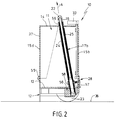
- Transport device comprises a compartment 11, case-like superstructure and one at the first Embodiment according to FIGS. 1 to 8 as a pull-out Drawer designed substructure 12.
- the compartment 11 is a bottom wall 13, a top wall 14 and four side walls 15a, 15b, 15c, 15d limited.
- At the Ceiling wall 14 is - approximately centrally - a handle body 16 arranged on which the transport device 10 u.a. from can be worn by a user.
- each three telescopically interlinked links 19, 20, 21 include.
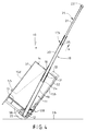
- the structure of the posts 17a, 17b can be seen best in Fig. 4.
- the three are telescopic sliding members, the support rod 19, the following is referred to as the base tube, the center tube 20 and the head tube 21 in the maximum extended position Condition shown.
- the two head pipes 21 are on the bottom wall 13 far end by means of a cross strut 22 with each other connected.
- the base 12 near the base 12 is firmly connected to the substructure 12. It occurs in an area of the bottom wall near the bottom wall edge 57 13 in the interior of the compartment 11 and reaches through a grommet-like guide 58 that is fixed to the bottom wall 13 of the compartment 11 is connected.
- the length of the Base tubes 19 correspond approximately to the height of the compartment 11.
- the center tubes 20 and those included therein Head tubes 21 pass through the top wall 14 of the compartment 11 approximately in the area of the handle body 16. Push it through in the same way, a grommet-like guide 59, which is firmly connected to the ceiling wall 14 and the stable suspension of the compartment 11 on the adjusting device 18 serves.
- the transport device On the base 12, two rollers 23 are arranged, the the mobile transport of the transport device 10 to serve.
- the transport device must be used for mobile transport 10 first in a tilted position, like shown, for example, in FIG. 4. This will be explained later.
- the pull bracket 35 can in the rest position of the Compartment 11, which is shown for example in FIGS. 1 and 2 is to be retracted so far that the cross strut 22 comes to rest on the handle body 16.
- the transport device 10 has one very compact shape and can be used by the user, accordingly a tool case.
- the drawbar 35 by pulling on the cross strut 22 with the head tubes 21 and the center tubes 20 in the extension direction A be extended.
- the extension movement is two Stops 24, 25 limited with corresponding Abutment surfaces 26, 27 cooperate on the respective ends of the center tubes near the bottom wall 13 20 or the head tubes 21 are arranged (see FIG. 3).
- the cross strut 22 is located in this extended state at a height in which is conveniently accessible to a user, so that this pull the transport device 10 comfortably or can push. This way the transportation especially relieved by heavy objects.
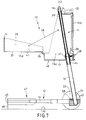
- the user To the compartment 11, starting from Fig. 2, from the Rest position in a working position far from the floor 36 6, the user must on the handle body 16 pull in extension direction A. It moves the compartment 11 in the extension direction A along the base tubes 19 up.
- the substructure 12 designed as a drawer the roller axis 27 are extended so that the Compartment 11 is more strongly supported and secured against tipping over is.
- Such a support is in principle not necessary, but advantageous.
- the working position the compartment 11 is reached when the middle tube 20 associated abutment surface 26 at the stop 24 of the base tube strikes. Then the middle tube can 20, the movement of the compartment 11 in the direction of extension A is moved along, no further from the Base tube 19 are extended.
- the tension bracket 35 with cross strut 22 and head tubes 21 can still be extended relative to compartment 11 when the compartment is in its working position located. In this way, the transport device 10 also slightly tilted and in the tilted Position can be driven comfortably when the compartment 11 has moved up to his off-ground working position.
- a holding device 28 is provided.
- a bolt 29 is of a spring 30 with its free end against the The outer circumference of the central tube 20 is applied. Since the Holding device 28 with the bolt 29 firmly on the compartment 11 is arranged, leads to a relative movement of the Compartment 11 relative to base 12, base tube 19 at the same time a relative movement to the bolt 29.
- in the upper free end of the base tube 19 is a bore 31 arranged, in which the bolt 29 engages when Bolt 29 and bore 31 in alignment with each other are brought. Then the bolt 29 acts as Locking body and prevents the compartment from sliding down 11 against the extension direction A down.
- the Compartment 11 is in its working position in this way secured.
- an automatic Created locking mechanism that engages, once the compartment 11 by the user in its working position brought. So there is nothing for the user additional handle required for locking.
- a shaft 32 is provided which is a handling part 33 connects with the bolt 28 such that an actuation of the handling part 33 a movement of the bolt 29 away from the base tube 19 and the compartment 11 for a downward movement against the Execution direction A releases.
- a second bore 34 is on the base rack 19 on his the respective roller 23 near the end. This serves to lock the compartment 11 in its Rest position.
- Drawbar 35 with cross strut 22, with head tube 21 and with Center tubes 20 extended into a position according to FIG. 4 are, with the exception that the compartment 11th is moved.
- Compartment 11 is to enable objects divided into a base body 40 and a drawer 37.
- the part of the compartment 11 designed as a drawer 37 is in the manner of a wing from the base body 40 of the compartment 11 can be folded away.
- the drawer 37 can additionally, for example with holding elements 38, held on the base body 40 be.
- a pull rope can be used as the holding element 38, for example are used, the one facing the drawer 37 Side on the side walls 39 of the drawer 37 and its opposite end on the side wall areas 15c and 15a of the base body 40 of the compartment 11 is attached.
- Locking element like lock provided that the drawer 37 secures on the base body 40 of the compartment 11. This is arranged for example on the ceiling wall 14.
- the in Items arranged in compartment 11 can partially also be arranged in the drawer 37. At the same time. provides the open drawer 37 with the bottom surface 41 User a desktop available.
- Holding elements 38, as well as the design of the drawer 37 themselves are only given as examples. It can also be considered to use split wing doors or the compartment 11 in the manner of several superimposed ones Train drawers.
- the substructure 12 shown in FIG. 8 is as Drawer formed and has an interior 42 Inclusion of other items, such as Small parts.
- a base support 43 is arranged on which the rollers 23rd are attached.
- Laterally of the interior 42 of the The drawer extends transversely from the base support 43 Telescopic rods 44 arranged. These exist each of several, in the embodiment three links, which is particularly clear from FIG. 7 becomes.
- the interior 42 is front of one Bar 45 completed, the edge near the bottom 36 46 is supported on the floor 36. To this way, a very stable substructure 12 is created.
- the exemplary embodiment according to FIGS. 9 to 12 differs from the embodiment described above by changing the design of the substructure 12.
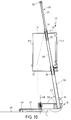
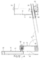
- two support feet 47 are provided, which are made of a rest position (Fig. 9) in a support position (Fig. 10) can be pivoted.
- the support feet 47 are hinged at one end to the base 12 and pivotable about an axis 48 which is substantially represents a normal to the floor 36.
- the two support feet 47 in the corner areas of the base 12 articulated so that their free Ends 49 lie opposite each other in the rest position.
- the two longitudinal axes L correspond to the support feet 47 a straight line, the two pivot axes 48 on the shortest route.
- the unfolding movement of the support feet 47 in a support position according to FIG. 10 represents movement of the support feet 47 in one plane
- the longitudinal axes of the two support feet 47 substantially spaced parallel to each other.
- a mechanism provided the unfolding and folding the support feet 47 automatically with a movement of the Compartment 11 connects relative to the substructure 12.
- a stamp 50 is shown schematically for this purpose, who constantly by a spring 51 in the direction the pivot axis 48 is applied towards the compartment 11.
- a translational movement of the stamp 50 becomes, for example through a screw thread in a swiveling movement a support leg 47 deflected.
- the handle body 16 in Cross section partially bowl-shaped and with its two ends on the ceiling wall 14 of the compartment 11 attached.
- the upper, concavely curved inner circumferential surface 52 of the handle body 16 corresponds essentially the outer peripheral surface 53 of the cross strut 22.
- the handle body 16 and ceiling wall 14 left opening 54 the handle body 16 together reach around with the cross strut 22. In this way is on the one hand a handle that is easy to grip from handle body 16 and cross strut 22 for the transport device 10 created.
- the user can with the handle also the compartment 11 relative to Height-adjustable base 12.
- the drawbar 35 is out the handle can be extended without an additional one Actuator is necessary.
- the inner peripheral surface 52 of the handle body 16 servess at the same time as Stop surface for the cross strut 22.
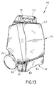
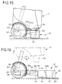
- the Underside of the compartment 11 two special locking means 60 in the manner of two axially relatively short pins intended. These engage with the one in the rest position Compartment 11, as in particular in FIGS. 13 and 15 becomes clear, in pocket-shaped counter-locking means 61 on the substructure 12.
- the outer surfaces of the cones 60 and the inner surfaces of the pockets 61 are in essentially tapered trapezoidal. When the pins 60 are inserted into the pockets 61 therefore slide the outer surfaces of the pin 60 on the Inner surfaces of the pockets 61 until a stop-forming Blocking effect occurs.
- the locking of the pins 60 with the pockets 61 is particularly advantageous in that an undressing of the substructure 12 in engagement with one another brought locking means 60 and counter locking means 61 prevented is.
- the transport device 10 for example in the manner of a suitcase by hand can be worn safely without the risk that the substructure 12 detaches itself and extends.
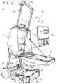
- FIGS. 13 to 16 also shows the peculiarity on that a support surface 63 on the substructure 12 is arranged on the handling objects, in particular Tools that can be put on.
- the contact surface 63 is divided into two, with respect to one the roller axis 56 fixed, i.e. not relocatable Support area 63a, and one with respect of the roller axis 56 displaceable, second contact surface area 63b.
- the shiftable contact area 63b becomes one from the top of the ceiling 65 a tool-forming chamber 64 provided.
- the chamber ceiling 65 can, for example be pivoted to access the in the To allow chamber located tools.
- the chamber ceiling 65 has over it also the advantage that the in the chamber 64th handling objects located through the ceiling 65 are additionally protected.
- the fixed contact surface area is located 63a when in the rest position Compartment 11 with respect to the displaceable contact surface area 63b at another vertical level. According to 15 is the fixed bearing surface area in this position 63a above the displaceable contact surface area 63b arranged.
- a pivotable web 66 is arranged on the substructure 12 in the area of the roller axis 56 .
- the web 66 is in the embodiment, manually from an essentially horizontal rest position (Fig. 15) in a essential vertical working position (Fig. 16) pivotable.
- the holding surface is in the working position 67 to the support surface 63 and not shown, optionally located on the support surface 63 Handling objects directed.
- the web 66 is also manually in its rest position 15 relocated.
- compartment 11 shows a holder 71 with a plurality of pockets 72, for example, for holding tools.
- the bracket 71 can i.a. for example at the Ceiling wall 14 of the compartment 11 are releasably attached.
Landscapes
- Engineering & Computer Science (AREA)
- Mechanical Engineering (AREA)
- Chemical & Material Sciences (AREA)
- Combustion & Propulsion (AREA)
- Transportation (AREA)
- Handcart (AREA)
- Manipulator (AREA)
- Container, Conveyance, Adherence, Positioning, Of Wafer (AREA)
- Drawers Of Furniture (AREA)
- Warehouses Or Storage Devices (AREA)
- Organic Low-Molecular-Weight Compounds And Preparation Thereof (AREA)
Priority Applications (1)
| Application Number | Priority Date | Filing Date | Title |
|---|---|---|---|
| EP04022748A EP1491297B1 (fr) | 1998-01-16 | 1998-11-13 | Dispositif de transport en particulier pour des appareils de manutention comme des outils, instruments ou analogue |
Applications Claiming Priority (4)
| Application Number | Priority Date | Filing Date | Title |
|---|---|---|---|
| DE29800665 | 1998-01-16 | ||
| DE29800665U | 1998-01-16 | ||
| DE19844372 | 1998-09-28 | ||
| DE19844372A DE19844372A1 (de) | 1998-01-16 | 1998-09-28 | Transportvorrichtung, insbesondere für Handhabungsgegenstände wie Werkzeuge, Instrumente o. dgl. |
Related Child Applications (1)
| Application Number | Title | Priority Date | Filing Date |
|---|---|---|---|
| EP04022748A Division EP1491297B1 (fr) | 1998-01-16 | 1998-11-13 | Dispositif de transport en particulier pour des appareils de manutention comme des outils, instruments ou analogue |
Publications (3)
| Publication Number | Publication Date |
|---|---|
| EP0930135A2 true EP0930135A2 (fr) | 1999-07-21 |
| EP0930135A3 EP0930135A3 (fr) | 2000-11-02 |
| EP0930135B1 EP0930135B1 (fr) | 2008-10-08 |
Family
ID=26049119
Family Applications (2)
| Application Number | Title | Priority Date | Filing Date |
|---|---|---|---|
| EP98121190A Expired - Lifetime EP0930135B1 (fr) | 1998-01-16 | 1998-11-13 | Dispositif de transport en particulier pour des appareils de manutention comme des outils, instruments ou analogue |
| EP04022748A Expired - Lifetime EP1491297B1 (fr) | 1998-01-16 | 1998-11-13 | Dispositif de transport en particulier pour des appareils de manutention comme des outils, instruments ou analogue |
Family Applications After (1)
| Application Number | Title | Priority Date | Filing Date |
|---|---|---|---|
| EP04022748A Expired - Lifetime EP1491297B1 (fr) | 1998-01-16 | 1998-11-13 | Dispositif de transport en particulier pour des appareils de manutention comme des outils, instruments ou analogue |
Country Status (6)
| Country | Link |
|---|---|
| US (1) | US6149168A (fr) |
| EP (2) | EP0930135B1 (fr) |
| AT (2) | ATE316450T1 (fr) |
| DE (3) | DE19844372A1 (fr) |
| DK (2) | DK1491297T3 (fr) |
| ES (2) | ES2256814T3 (fr) |
Cited By (6)
| Publication number | Priority date | Publication date | Assignee | Title |
|---|---|---|---|---|
| US6662748B1 (en) * | 2002-07-23 | 2003-12-16 | Robert Hanks | Litter box apparatus |
| DE102004044959A1 (de) * | 2004-09-16 | 2006-04-06 | Chen, Tsai-Ching, Fu Hsing | Kombinierter Werkzeugkasten |
| FR2909629A1 (fr) * | 2006-12-11 | 2008-06-13 | Pascal Maurice Vincent Curabec | Coffre roulant a brancards escamotables |
| EP1409150A4 (fr) * | 1999-10-05 | 2008-08-13 | Mi Ok Pty Ltd | Boite a outils portable |
| CN106272294A (zh) * | 2014-12-16 | 2017-01-04 | 青岛智享专利技术开发有限公司 | 电工可背负式升降工具包 |
| CN111496400A (zh) * | 2020-05-30 | 2020-08-07 | 瑭圭函 | 一种金属激光切割机机体移动架 |
Families Citing this family (28)
| Publication number | Priority date | Publication date | Assignee | Title |
|---|---|---|---|---|
| CA2450948A1 (fr) * | 2001-05-17 | 2002-11-21 | Darren J. Kady | Accessoires pour chariot pliable |
| AT414106B (de) | 2002-09-17 | 2006-09-15 | Stoellinger Franz Ing | Fahrbarer, händisch schiebbarer und zusammenlegbarer untersatz für einen kistenförmigen behälter |
| US6832670B2 (en) * | 2003-01-06 | 2004-12-21 | Richard H. Wolters | Convertible travel case |
| US7246805B2 (en) * | 2003-12-19 | 2007-07-24 | Neal Phillip H | Apparatus and method for convertible cargo carrier |
| US7431313B1 (en) | 2006-05-23 | 2008-10-07 | Jose Torres | Portable tool storage apparatus |
| US7766161B2 (en) * | 2007-02-12 | 2010-08-03 | Jesse Maxwell Good | Portable tool box |
| US7870937B1 (en) * | 2007-03-19 | 2011-01-18 | Albert Arnao | Combination luggage and computer workstation |
| RU2333861C1 (ru) * | 2007-05-02 | 2008-09-20 | Александр Иванович Худолий | Ручная хозяйственная тележка |
| US8540063B2 (en) * | 2007-10-22 | 2013-09-24 | Aaron LaTowsky | Wheeled luggage with extendable supportive tongue |
| US8118146B2 (en) * | 2008-07-07 | 2012-02-21 | Netta Shalgi | Wheeled luggage case |
| TWM353856U (en) * | 2008-07-10 | 2009-04-01 | Rui-Jia Wang | Pull rod cart structure |
| GB0818222D0 (en) * | 2008-10-04 | 2008-11-12 | Mountway Ltd | Improvements in and relating to chair lifts |
| US7997595B1 (en) * | 2009-03-16 | 2011-08-16 | Daniel Lee Pope | Disc golf caddy |
| US8061723B1 (en) * | 2009-06-26 | 2011-11-22 | Tcr Products Llc | Vertically extendable equipment storage bucket apparatus and method |
| US8567799B2 (en) * | 2010-12-28 | 2013-10-29 | Angélica Figueiredo White | Wheeled K-12 book carrier and organizer |
| USD657110S1 (en) | 2011-08-10 | 2012-04-03 | Schlomann Brian K | Brake maintenance cart |
| WO2014113036A1 (fr) | 2013-01-21 | 2014-07-24 | Eikman Edward A | Garrots veineux jetables comprenant une partie support d'indice amovible, et procédés d'utilisation |
| US9079595B2 (en) * | 2013-12-11 | 2015-07-14 | E-Make Co., Ltd. | Mobile cart |
| US10076167B2 (en) * | 2016-06-13 | 2018-09-18 | Soon Young KIM | Luggage system with transport platform |
| CN107600136A (zh) * | 2017-09-22 | 2018-01-19 | 上海波鸿医疗器械科技有限公司 | 一种可折叠的医用台车 |
| DE202017107444U1 (de) | 2017-11-20 | 2018-01-02 | Parat Beteiligungs Gmbh | Vorrichtung zum Transport und zur Aufbewahrung von Gegenständen |
| US20190281942A1 (en) * | 2018-03-15 | 2019-09-19 | Joy Tong | Luggage case with bi-directional handle for pulling case and for raising height of case |
| US10889311B2 (en) * | 2019-05-09 | 2021-01-12 | Steve Madrid | Medical instruments stroller |
| US11352210B1 (en) * | 2019-11-13 | 2022-06-07 | Charles Smith | Methods of moving tires toward or away from vehicles using tire dolly assemblies |
| TWI745798B (zh) * | 2019-12-12 | 2021-11-11 | 陳霈琳 | 抽屜式工具箱 |
| DE102020100923A1 (de) | 2020-01-16 | 2021-07-22 | Parat Beteiligungs Gmbh | Vorrichtung zur Aufbewahrung und zum Transport von Handhabungsgegenständen |
| US11633027B2 (en) * | 2020-01-31 | 2023-04-25 | Veto Pro Pac, Llc | Wheeled carrier with telescoping center handle |
| US11478051B1 (en) | 2021-05-21 | 2022-10-25 | Gary Lee Robinson | Automatic latch for a two-piece container |
Family Cites Families (17)
| Publication number | Priority date | Publication date | Assignee | Title |
|---|---|---|---|---|
| GB746995A (en) * | 1953-05-02 | 1956-03-21 | Alfred Zerver | Improvements in or relating to a tool-or equipment-box or the like, more particularly for repair workshops |
| US2964328A (en) * | 1959-02-20 | 1960-12-13 | David L Muir | Tool cart |
| US4062565A (en) * | 1976-11-01 | 1977-12-13 | Holtz Gilbert J | Collapsible baggage cart |
| US4119044A (en) * | 1977-01-17 | 1978-10-10 | Merlin J. Peterson | Tool caddy |
| US4258962A (en) * | 1979-11-05 | 1981-03-31 | Slaugh Mervin J | Carousel tool and parts kit |
| SE458581B (sv) * | 1986-01-24 | 1989-04-17 | Nils Andersson | Transportabel baerbar servicebox |
| US5002293A (en) * | 1986-11-20 | 1991-03-26 | Gottselig John C | Painter's service cart |
| DE3723464A1 (de) * | 1987-07-16 | 1989-01-26 | Stabilus Gmbh | Werkzeugwagen mit hebehilfe |
| US5074571A (en) * | 1990-12-05 | 1991-12-24 | Reese Charles F | Spare bowling ball carrier |
| US5240264A (en) * | 1992-01-27 | 1993-08-31 | Williams Thomas L | Containers on folding wheels and method |
| US5374073A (en) * | 1993-02-08 | 1994-12-20 | Hung-Hsin; Hsieh | Tractive baggage handcart |
| US5380023A (en) * | 1993-03-15 | 1995-01-10 | Mcbee; Beverlee | Child's vehicle for increased visual interaction |
| US5927833A (en) * | 1993-05-03 | 1999-07-27 | Kelley; James O. | Concealed desk |
| US5590897A (en) * | 1994-12-06 | 1997-01-07 | Tsai; James | Structure of carriage |
| US5653319A (en) * | 1995-01-25 | 1997-08-05 | Wang; King-Sheng | Retractable handle for a wheeled travel bag |
| US5730264A (en) * | 1996-11-15 | 1998-03-24 | Ting Cheng Co., Ltd. | Luggage structure for transporting a plurality of cases |
| US5951037A (en) * | 1997-08-07 | 1999-09-14 | Hsieh; Hung-Ching | Luggage cart |
-
1998
- 1998-09-28 DE DE19844372A patent/DE19844372A1/de not_active Withdrawn
- 1998-11-13 DK DK04022748T patent/DK1491297T3/da active
- 1998-11-13 EP EP98121190A patent/EP0930135B1/fr not_active Expired - Lifetime
- 1998-11-13 ES ES04022748T patent/ES2256814T3/es not_active Expired - Lifetime
- 1998-11-13 AT AT04022748T patent/ATE316450T1/de not_active IP Right Cessation
- 1998-11-13 DK DK98121190T patent/DK0930135T3/da active
- 1998-11-13 DE DE59814298T patent/DE59814298D1/de not_active Expired - Lifetime
- 1998-11-13 ES ES98121190T patent/ES2314984T3/es not_active Expired - Lifetime
- 1998-11-13 AT AT98121190T patent/ATE410270T1/de active
- 1998-11-13 DE DE59813351T patent/DE59813351D1/de not_active Expired - Fee Related
- 1998-11-13 EP EP04022748A patent/EP1491297B1/fr not_active Expired - Lifetime
-
1999
- 1999-01-15 US US09/232,872 patent/US6149168A/en not_active Expired - Fee Related
Non-Patent Citations (1)
| Title |
|---|
| None |
Cited By (11)
| Publication number | Priority date | Publication date | Assignee | Title |
|---|---|---|---|---|
| EP1409150A4 (fr) * | 1999-10-05 | 2008-08-13 | Mi Ok Pty Ltd | Boite a outils portable |
| US6662748B1 (en) * | 2002-07-23 | 2003-12-16 | Robert Hanks | Litter box apparatus |
| DE102004044959A1 (de) * | 2004-09-16 | 2006-04-06 | Chen, Tsai-Ching, Fu Hsing | Kombinierter Werkzeugkasten |
| DE102004044959B4 (de) * | 2004-09-16 | 2010-01-07 | Chen, Tsai-Ching, Fu Hsing | Kombinierter Werkzeugkasten |
| FR2909629A1 (fr) * | 2006-12-11 | 2008-06-13 | Pascal Maurice Vincent Curabec | Coffre roulant a brancards escamotables |
| WO2008087274A1 (fr) * | 2006-12-11 | 2008-07-24 | Pascal Curabec | Coffre roulant a brancards escamotables. |
| CN106272294A (zh) * | 2014-12-16 | 2017-01-04 | 青岛智享专利技术开发有限公司 | 电工可背负式升降工具包 |
| CN106393026A (zh) * | 2014-12-16 | 2017-02-15 | 戴亚细 | 一种电工工具包 |
| CN106272294B (zh) * | 2014-12-16 | 2018-12-07 | 春秋航空技术发展江苏有限公司 | 电工可背负式升降工具包 |
| CN111496400A (zh) * | 2020-05-30 | 2020-08-07 | 瑭圭函 | 一种金属激光切割机机体移动架 |
| CN111496400B (zh) * | 2020-05-30 | 2020-11-20 | 詹纯 | 一种金属激光切割机机体移动架 |
Also Published As
| Publication number | Publication date |
|---|---|
| ATE410270T1 (de) | 2008-10-15 |
| EP1491297B1 (fr) | 2006-01-25 |
| EP1491297A1 (fr) | 2004-12-29 |
| DE59814298D1 (de) | 2008-11-20 |
| EP0930135B1 (fr) | 2008-10-08 |
| ES2256814T3 (es) | 2006-07-16 |
| EP0930135A3 (fr) | 2000-11-02 |
| DK0930135T3 (da) | 2009-01-19 |
| ATE316450T1 (de) | 2006-02-15 |
| DK1491297T3 (da) | 2006-03-06 |
| DE19844372A1 (de) | 1999-07-22 |
| US6149168A (en) | 2000-11-21 |
| ES2314984T3 (es) | 2009-03-16 |
| DE59813351D1 (de) | 2006-04-13 |
Similar Documents
| Publication | Publication Date | Title |
|---|---|---|
| EP0930135B1 (fr) | Dispositif de transport en particulier pour des appareils de manutention comme des outils, instruments ou analogue | |
| EP1059239A1 (fr) | Récipient portatif | |
| EP0681890B1 (fr) | Chevalet de travail et de montage | |
| DE102011050823B4 (de) | Werkzeugbehälter | |
| DE3245842C2 (de) | Krankentransportgerät, insbesondere Krankentrage | |
| EP0207419B1 (fr) | Boîte à outils | |
| DE19540056C1 (de) | Kombinierter Bett-Nachttisch | |
| DE29817353U1 (de) | Transportvorrichtung, insbesondere für Handhabungsgegenstände wie Werkzeuge, Instrumente o.dgl. | |
| DE19540058C1 (de) | Kombinierter Bett-Nachttisch | |
| DE69111808T2 (de) | Vorrichtung für zerlegbare gegenstände. | |
| DE19540059C1 (de) | Kombinierter Bett-Nachttisch | |
| DE19540057C1 (de) | Kombinierter Bett-Nachttisch | |
| DE10105847B4 (de) | Mitnahmevorrichtung für ausziehbaren Möbelboden | |
| WO2012163345A2 (fr) | Contenant à outils | |
| DE19540055C1 (de) | Kombinierter Bett-Nachttisch | |
| DE6602991U (de) | Lastdrueckgeraet, insbesondere fuer hubkarren | |
| EP0464168A1 (fr) | Systeme de poignee pour valise a roulettes ou analogue | |
| DE2357738C2 (de) | Nachttisch mit seitlich einschwenkbarer und ausfahrbarer Tischplatte | |
| DE29718383U1 (de) | Transportvorrichtung zum Transport von Gegenständen, wie Werkzeugschränke, Materialboxen, Waschmaschinen o.dgl. | |
| DE19952483C1 (de) | Verriegelungsvorrichtung für nebeneinander angeordnete Hubwagen | |
| DE2939654A1 (de) | Arbeitsbuehne | |
| DE9412060U1 (de) | Rollgestell für Lasten | |
| DE9404121U1 (de) | Arbeits- und Montagebock | |
| DE2519344C3 (de) | Mehrteiliger Aufbewahrungsbehälter für Werkzeuge und Kleinmaterialien | |
| DE102011002311B4 (de) | Bestattungsfahrzeug mit Staufach für Sargroller |
Legal Events
| Date | Code | Title | Description |
|---|---|---|---|
| PUAI | Public reference made under article 153(3) epc to a published international application that has entered the european phase |
Free format text: ORIGINAL CODE: 0009012 |
|
| AK | Designated contracting states |
Kind code of ref document: A2 Designated state(s): AT BE CH DE DK ES FI FR IT LI LU NL SE |
|
| AX | Request for extension of the european patent |
Free format text: AL;LT;LV;MK;RO;SI |
|
| PUAL | Search report despatched |
Free format text: ORIGINAL CODE: 0009013 |
|
| AK | Designated contracting states |
Kind code of ref document: A3 Designated state(s): AT BE CH CY DE DK ES FI FR GB GR IE IT LI LU MC NL PT SE |
|
| AX | Request for extension of the european patent |
Free format text: AL;LT;LV;MK;RO;SI |
|
| 17P | Request for examination filed |
Effective date: 20001026 |
|
| AKX | Designation fees paid |
Free format text: AT BE CH DE DK ES FI FR IT LI LU NL SE |
|
| 17Q | First examination report despatched |
Effective date: 20010927 |
|
| APBN | Date of receipt of notice of appeal recorded |
Free format text: ORIGINAL CODE: EPIDOSNNOA2E |
|
| APBR | Date of receipt of statement of grounds of appeal recorded |
Free format text: ORIGINAL CODE: EPIDOSNNOA3E |
|
| APBR | Date of receipt of statement of grounds of appeal recorded |
Free format text: ORIGINAL CODE: EPIDOSNNOA3E |
|
| APBV | Interlocutory revision of appeal recorded |
Free format text: ORIGINAL CODE: EPIDOSNIRAPE |
|
| GRAP | Despatch of communication of intention to grant a patent |
Free format text: ORIGINAL CODE: EPIDOSNIGR1 |
|
| APBV | Interlocutory revision of appeal recorded |
Free format text: ORIGINAL CODE: EPIDOSNIRAPE |
|
| GRAS | Grant fee paid |
Free format text: ORIGINAL CODE: EPIDOSNIGR3 |
|
| GRAA | (expected) grant |
Free format text: ORIGINAL CODE: 0009210 |
|
| AK | Designated contracting states |
Kind code of ref document: B1 Designated state(s): AT BE CH DE DK ES FI FR IT LI LU NL SE |
|
| REG | Reference to a national code |
Ref country code: CH Ref legal event code: EP |
|
| REF | Corresponds to: |
Ref document number: 59814298 Country of ref document: DE Date of ref document: 20081120 Kind code of ref document: P |
|
| REG | Reference to a national code |
Ref country code: SE Ref legal event code: TRGR |
|
| REG | Reference to a national code |
Ref country code: DK Ref legal event code: T3 |
|
| REG | Reference to a national code |
Ref country code: CH Ref legal event code: NV Representative=s name: MOINAS & SAVOYE SA |
|
| REG | Reference to a national code |
Ref country code: ES Ref legal event code: FG2A Ref document number: 2314984 Country of ref document: ES Kind code of ref document: T3 |
|
| PLBE | No opposition filed within time limit |
Free format text: ORIGINAL CODE: 0009261 |
|
| STAA | Information on the status of an ep patent application or granted ep patent |
Free format text: STATUS: NO OPPOSITION FILED WITHIN TIME LIMIT |
|
| 26N | No opposition filed |
Effective date: 20090709 |
|
| PG25 | Lapsed in a contracting state [announced via postgrant information from national office to epo] |
Ref country code: LU Free format text: LAPSE BECAUSE OF NON-PAYMENT OF DUE FEES Effective date: 20081113 |
|
| PGFP | Annual fee paid to national office [announced via postgrant information from national office to epo] |
Ref country code: AT Payment date: 20101125 Year of fee payment: 13 |
|
| PGFP | Annual fee paid to national office [announced via postgrant information from national office to epo] |
Ref country code: IT Payment date: 20101027 Year of fee payment: 13 |
|
| REG | Reference to a national code |
Ref country code: DE Ref legal event code: R081 Ref document number: 59814298 Country of ref document: DE Owner name: PARAT BETEILIGUNGS GMBH, DE Free format text: FORMER OWNER: PARAT SCHOENENBACH GMBH + CO. KG, 42897 REMSCHEID, DE Effective date: 20110811 |
|
| REG | Reference to a national code |
Ref country code: CH Ref legal event code: PUE Owner name: PARAT BETEILIGUNGS GMBH Free format text: PARAT-WERK SCHOENENBACH GMBH + CO KG#TENTER WEG 1-3#D-42897 REMSCHEID (DE) -TRANSFER TO- PARAT BETEILIGUNGS GMBH#SCHACHTLAU 3-4#94089 NEUREICHENAU (DE) |
|
| REG | Reference to a national code |
Ref country code: FR Ref legal event code: TP Owner name: PARAT BETEILIGUNGS GMBH, DE Effective date: 20110929 Ref country code: FR Ref legal event code: CD Owner name: PARAT BETEILIGUNGS GMBH, DE Effective date: 20110929 |
|
| BECH | Be: change of holder |
Owner name: PARAT BETEILIGUNGS G.M.B.H. Effective date: 20111004 |
|
| BECN | Be: change of holder's name |
Owner name: PARAT BETEILIGUNGS G.M.B.H. Effective date: 20111004 |
|
| REG | Reference to a national code |
Ref country code: NL Ref legal event code: TD Effective date: 20111214 Ref country code: NL Ref legal event code: SD Effective date: 20111214 |
|
| PGFP | Annual fee paid to national office [announced via postgrant information from national office to epo] |
Ref country code: SE Payment date: 20111124 Year of fee payment: 14 Ref country code: CH Payment date: 20111123 Year of fee payment: 14 Ref country code: NL Payment date: 20111128 Year of fee payment: 14 Ref country code: ES Payment date: 20111201 Year of fee payment: 14 Ref country code: FI Payment date: 20111103 Year of fee payment: 14 Ref country code: FR Payment date: 20111201 Year of fee payment: 14 Ref country code: DK Payment date: 20111116 Year of fee payment: 14 |
|
| PGFP | Annual fee paid to national office [announced via postgrant information from national office to epo] |
Ref country code: BE Payment date: 20111130 Year of fee payment: 14 |
|
| REG | Reference to a national code |
Ref country code: AT Ref legal event code: PC Ref document number: 410270 Country of ref document: AT Kind code of ref document: T Owner name: PARAT BETEILIGUNGS GMBH, DE Effective date: 20121019 |
|
| PGFP | Annual fee paid to national office [announced via postgrant information from national office to epo] |
Ref country code: DE Payment date: 20121127 Year of fee payment: 15 |
|
| BERE | Be: lapsed |
Owner name: PARAT BETEILIGUNGS G.M.B.H. Effective date: 20121130 |
|
| REG | Reference to a national code |
Ref country code: NL Ref legal event code: V1 Effective date: 20130601 |
|
| REG | Reference to a national code |
Ref country code: CH Ref legal event code: PL |
|
| REG | Reference to a national code |
Ref country code: DK Ref legal event code: EBP |
|
| REG | Reference to a national code |
Ref country code: AT Ref legal event code: MM01 Ref document number: 410270 Country of ref document: AT Kind code of ref document: T Effective date: 20121113 |
|
| PG25 | Lapsed in a contracting state [announced via postgrant information from national office to epo] |
Ref country code: AT Free format text: LAPSE BECAUSE OF NON-PAYMENT OF DUE FEES Effective date: 20121113 Ref country code: CH Free format text: LAPSE BECAUSE OF NON-PAYMENT OF DUE FEES Effective date: 20121130 Ref country code: LI Free format text: LAPSE BECAUSE OF NON-PAYMENT OF DUE FEES Effective date: 20121130 Ref country code: SE Free format text: LAPSE BECAUSE OF NON-PAYMENT OF DUE FEES Effective date: 20121114 |
|
| REG | Reference to a national code |
Ref country code: FR Ref legal event code: ST Effective date: 20130731 |
|
| PG25 | Lapsed in a contracting state [announced via postgrant information from national office to epo] |
Ref country code: IT Free format text: LAPSE BECAUSE OF NON-PAYMENT OF DUE FEES Effective date: 20121113 Ref country code: NL Free format text: LAPSE BECAUSE OF NON-PAYMENT OF DUE FEES Effective date: 20130601 Ref country code: BE Free format text: LAPSE BECAUSE OF NON-PAYMENT OF DUE FEES Effective date: 20121130 Ref country code: FI Free format text: LAPSE BECAUSE OF NON-PAYMENT OF DUE FEES Effective date: 20121113 |
|
| PG25 | Lapsed in a contracting state [announced via postgrant information from national office to epo] |
Ref country code: DK Free format text: LAPSE BECAUSE OF NON-PAYMENT OF DUE FEES Effective date: 20121130 |
|
| PG25 | Lapsed in a contracting state [announced via postgrant information from national office to epo] |
Ref country code: FR Free format text: LAPSE BECAUSE OF NON-PAYMENT OF DUE FEES Effective date: 20121130 |
|
| REG | Reference to a national code |
Ref country code: ES Ref legal event code: FD2A Effective date: 20140306 |
|
| PG25 | Lapsed in a contracting state [announced via postgrant information from national office to epo] |
Ref country code: ES Free format text: LAPSE BECAUSE OF NON-PAYMENT OF DUE FEES Effective date: 20121114 |
|
| REG | Reference to a national code |
Ref country code: DE Ref legal event code: R119 Ref document number: 59814298 Country of ref document: DE Effective date: 20140603 |
|
| PG25 | Lapsed in a contracting state [announced via postgrant information from national office to epo] |
Ref country code: DE Free format text: LAPSE BECAUSE OF NON-PAYMENT OF DUE FEES Effective date: 20140603 |