EP0930137B1 - Procédé et appareil pour le transport d'un objet - Google Patents
Procédé et appareil pour le transport d'un objet Download PDFInfo
- Publication number
- EP0930137B1 EP0930137B1 EP98123379A EP98123379A EP0930137B1 EP 0930137 B1 EP0930137 B1 EP 0930137B1 EP 98123379 A EP98123379 A EP 98123379A EP 98123379 A EP98123379 A EP 98123379A EP 0930137 B1 EP0930137 B1 EP 0930137B1
- Authority
- EP
- European Patent Office
- Prior art keywords
- slider
- movement
- transport
- accordance
- rear side
- Prior art date
- Legal status (The legal status is an assumption and is not a legal conclusion. Google has not performed a legal analysis and makes no representation as to the accuracy of the status listed.)
- Expired - Lifetime
Links
Images


Classifications
-
- B—PERFORMING OPERATIONS; TRANSPORTING
- B26—HAND CUTTING TOOLS; CUTTING; SEVERING
- B26D—CUTTING; DETAILS COMMON TO MACHINES FOR PERFORATING, PUNCHING, CUTTING-OUT, STAMPING-OUT OR SEVERING
- B26D7/00—Details of apparatus for cutting, cutting-out, stamping-out, punching, perforating, or severing by means other than cutting
- B26D7/06—Arrangements for feeding or delivering work of other than sheet, web, or filamentary form
- B26D7/0625—Arrangements for feeding or delivering work of other than sheet, web, or filamentary form by endless conveyors, e.g. belts
-
- B—PERFORMING OPERATIONS; TRANSPORTING
- B26—HAND CUTTING TOOLS; CUTTING; SEVERING
- B26D—CUTTING; DETAILS COMMON TO MACHINES FOR PERFORATING, PUNCHING, CUTTING-OUT, STAMPING-OUT OR SEVERING
- B26D7/00—Details of apparatus for cutting, cutting-out, stamping-out, punching, perforating, or severing by means other than cutting
- B26D7/06—Arrangements for feeding or delivering work of other than sheet, web, or filamentary form
- B26D7/0608—Arrangements for feeding or delivering work of other than sheet, web, or filamentary form by pushers
-
- B—PERFORMING OPERATIONS; TRANSPORTING
- B26—HAND CUTTING TOOLS; CUTTING; SEVERING
- B26D—CUTTING; DETAILS COMMON TO MACHINES FOR PERFORATING, PUNCHING, CUTTING-OUT, STAMPING-OUT OR SEVERING
- B26D7/00—Details of apparatus for cutting, cutting-out, stamping-out, punching, perforating, or severing by means other than cutting
- B26D7/06—Arrangements for feeding or delivering work of other than sheet, web, or filamentary form
- B26D7/0683—Arrangements for feeding or delivering work of other than sheet, web, or filamentary form specially adapted for elongated articles
Definitions
- the invention relates to a method for transporting a person on a support surface subject to a processing facility, in particular a cutting device, and a device to carry out this process.
- DE 195 18 583 A1 discloses a method with features of The preamble of claim 1 and a device with the features the preamble of claim 11 known.
- This font describes a cutting machine for slicing product slices.
- This cutting machine has a feeder with a lower feed conveyor, which is an endless flexible conveyor belt having. Furthermore, a collet unit is provided with the the rear end of the product loaf works together.
- Direction of a processing device can be transported.
- the method or device is intended to enable the article also during its processing in the processing facility maintains its position relative to the support surface and not unintentionally changes.
- This task is performed by a procedure with the characteristics of claim 1.
- a slider at least temporarily at the back of a on a support surface resting object arranged and synchronous moved to a transport movement of the article, wherein the slider then at the earliest to the back of the object is led, while already a part of the object by the processing device is processed, especially if already one or two pieces have been separated.
- the processing of the object takes place on the opposite side of the article from the back.
- the slider does not have be arranged from the outset at the back of the article.
- the slider at such time to the back of the The object to which the processing device is directed facing side of the article from a processing means, for example, a cutting means is supported. This will cause an inadvertent, moving caused by moving the slider prevents the article in the direction of the processing device.
- the object of the invention is also achieved by a device solved with the features of claim 11.
- the slider to its removal from the back of the object pivoted out of the path of movement of the object such that the fulcrum of this pivoting movement is outside, in particular above, the trajectory of the object is located.
- the object is thus during its transport between the hold-down and the bearing surface pinched; by that he is with respect to one unintentional movement in both the vertical direction and in Stabilized direction of the transport movement.
- the object synchronous drive of the holddown takes place This transport movement even at high accelerations or Delays without unintentional, due to the inertia of the object conditional slippage of the object.
- This allows a high Dynamics of transport and subsequent processing.
- the slider is attached to the back of the article created.
- that side of the Item referred to as the back which is contrary to the direction of the intended Transport movement of the article points.
- the slider and the hold-down become to achieve these stabilization effects moved synchronously with the transport movement of the object or driven.
- the actual drive of the article takes place to its transport movement essentially by a corresponding Movement of the bearing surface, in particular as a conveyor belt is trained.
- the movement of the slider or the drive of the hold-down supportive with respect to the drive movement the bearing surface.
- the invention proves to be particularly effective when it comes to the to be transported and processed object to a substantially elongated and flexible or compressible object acts, such as a cheese bar.
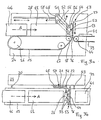
- FIGS. 1a and 1b show a schematic side view and top view, respectively a device for transporting an article 11, for example an elongated cheese crucible, towards a cutting device 13.
- the object 11 is located on the serving as a support surface Top of an endless conveyor belt 15. This is about three transport rollers 16, 17, 18 clamped and with its top in a transport direction A movable.
- the transport rollers 16, 17, 18 are over waves 20, 21 and 22 with respect to the illustration of FIG. 1a behind the conveyor belt 15 arranged drive unit 24 is connected.
- a flat slide 26 is arranged, the via a guide bracket 27 also with the drive unit 24th connected is. There is the guide bracket 27 along a closed Loop running, in Fig. 1a partially drawn by dashed lines Guide rail 28 out.
- a hold-down 29 engages the top of the article 11.
- This has an endless hold-down band 30 that passes through two waves 31, 32 connected to the drive unit 24 drive rollers 33 and 34th is stretched.
- the hold-down band 30 has perpendicular to the transport direction A is a lower and in the direction of transport A a substantial less expansion than the conveyor belt 15th
- the drive unit 24 has drive means, not shown in the figures to drive the conveyor belt 15 and its transport rollers 16, 17, 18, of the slider 26 and the hold-down band 30 and its Drive rollers 33, 34. These drive means each comprise each other synchronized servomotors.
- the cutting device 13 is the conveyor belt 15 and the hold-down 29 arranged in the transport direction A immediately adjacent. she has a downwardly directed cutting blade 36 extending from the Drive unit 24 from in the horizontal direction and perpendicular to the transport direction A extends along the entire width of the conveyor belt 15. On the drive unit 24, the cutting blade 36 is within a Guide rail 37 is guided, extending in the vertical direction from the top of the conveyor belt 15 extends to the level of the blank holder 29.
- a conveyor belt 39 for the removal of the object 11 cut off Arranged pieces.
- On top of the conveyor belt 39 which is about at the same height as the top of the conveyor belt 15, such is by means of the cutting device 13 of the article 11 separated and tilted by 90 ° piece 41 to recognize.
- the left part of the conveyor belt 39 is shown where it by a conveyor roller 44, which via a shaft 43 with the drive unit 24 is connected, is clamped.
- the conveyor belt 15 serves to bring the article 11 in Direction A of the processing device 13 and there to the gradual Transport: After every transport step, after the restart of the conveyor belt 15, the cutting blade 36 along the Guide rail 37 - as indicated by the vertical arrow B - in vertical direction down and back up to a Piece with a width corresponding to the transport step of the object 11 to separate and tilt on the conveyor belt 39. Subsequently the conveyor belt 15 is a further transport step moved while simultaneously tilted onto the conveyor belt 39 Piece 41 is conveyed away from this in the direction A, for example to a packaging device.
- the Slider 26 is at least temporarily during transport of the article 11 arranged at the back.
- the slider 26 becomes synchronous moved to the transport movement of the article 11.
- the transport movement of the article 11 since Slipping of the article 11 against the direction A too high Acceleration of the article 11 by means of the conveyor belt 15 in Direction A is prevented.
- the slider 26 prevents a in particular by the width of the cutting blade 36 or by a soft, flexible consistency of the article 11 conditional slippage of the Item 11 during a cutting operation while stationary Conveyor belt 15.
- the slider 26 along the lower part of the guide rail 28 in horizontal direction until cutting the last one Piece until led to the cutting device 13.
- the slider 26 is returned a short distance, i. against the direction A, and up past the hold 29, around the top of the guide rail 28 to the beginning, i.e. the opposite of the direction A located end of the conveyor belt 15 to be led.
- a subsequent Object by means of the conveyor belt 15 in continuous motion, i.e. without intermediate braking, past the slider 26 transported in the direction of the cutting device 13.
- the slide 26 In addition to the slide 26 also supports the hold-down 29 the transport movement of the object exerts slight pressure on the object 11 and synchronously with its Transport movement is increased, it increases the static friction of the Item 11 with respect to the conveyor belt 15 and effected by his own contact with the item 11 further friction liability.
- the hold-down 29 prevents unintentional slipping of the article 11 with respect to the conveyor belt 15 both during a transport movement or an acceleration required for this purpose or delay, as well as during one by the cutter 13 performed on the stationary object 11 processing operation.
- the hold-down 29 prevents upward movement of the object 11 at startup of the cutting blade 36, and he can premature Tipping over the last piece cut from the article 11 prevent or intentionally tip over such a piece Direction of the conveyor belt 39 cause.
- the hold-down 29 may alternatively to the structure as a hold-down band 30 also as a driven Hold-down roller be formed.
- the combination of slider 26 and hold 29 for the device shown in Figures 1a and 1b and for the above described method a particularly high dynamics: the subject 11 may for each machining operation in the cutting device 13 fast, i. with high acceleration or deceleration to one Step in the direction of the cutting device 13 are transported.
- Fig. 2 is another device for transporting an article 11th in the direction of a cutting device 13, wherein the same reference numerals as in Figures 1a and 1b respectively the same or similar Designate parts.
- the object 11 is through the Conveyor belt 15 gradually in the direction A to the cutter 13 transported while in this after completion of each transport step by vertical movement of the cutting blade 36 individual pieces 41st be separated from the article 11.
- Fig. 2 is a time of Transport and cutting process shown, to which just cutting of a preceding article has been completed so that of this previous article only the last, on the conveyor belt 39 located piece 41 can be seen.
- the next-to-be-cut object 11 transported to the cutter 13, immediately after the slider 26 along the guide rail 28 in the vertical direction led out of the transport path of the article 11 has been. Subsequently, already with the processing of the object 11 started by the cutter 13 during the Slider 26 still opposite to the transport direction A of the article 11th is moved along the upper part of the guide rail 28.
- the slider 26 only then moves back down into the path of movement of the article 11 when e.g. already two pieces of the object 11 have been separated and the back of the object 11th the direction A rear portion of the guide rail 28th happened. Subsequently, the slider 26 is attached to the back of the article 11 applied while the conveyor belt 15 and thus the object 11 stops and the cutting blade 36 assumes a lower position, in which they are located in the direction of transport A end of the object 11 supported.
- the slider 26 also takes over in the device or the method As shown in FIG. 2, the function, the object 11 against unintentional Slipping against the direction A support to a higher acceleration and thus to allow a higher dynamics.
- the slider 26 but only at a time to the back of the article 11 is approached, to which the opposite of the back Page of item 11 is already being processed, goes the for returning to the back of the article 11 does not take time for the actual editing of the item 11 lost; the rate at which item 11 processes, for example can be cut, thus is further increased.
- FIGS. 3a and 3b show a schematic side view and top view, respectively another device for transporting an article 11 in Direction of a cutting device 13.
- the same reference numerals designate as in the figures described above, each same or similar parts.
- the Slider 26 along only in the horizontal direction on the drive unit 24 extending guide rail 28 out. It's a one along the guide rail 28 guided slide 48 is provided with the the slide 26 via an in the plan view of FIG. 3b L-shaped Swivel arm 50 is connected.
- the pivot arm 50 has two in vertical Direction offset to each other and arranged in parallel parallel arms 51, 52, each with one end on the carriage 48 and with the other end on the drive unit 24 facing side of the slider 26 are articulated.
- the slider 26 has two circular section, in the transport direction A and downwardly extendable claws 53, which in the figures 3a and 3b are shown in dashed lines in a state in which they engage in a final piece 54 of a preceding item.
- the device shown in Figures 3a and 3b is used for gradual transport and cutting of the item 11.
- the at the Rear side of the article 11 arranged and moved synchronously with this Slider 26 prevents the article 11 slipping back during its transport or during its processing.
- the two Claws 53 prevent tipping 54 of the piece after this as the last one has been cut out of an object. By driving back The claws 53 may tilt this piece 54 to a desired Time allows, supports or causes.
- the embodiment of the slider 26 with a Swivel arm 50 allows a particularly simple drive and a easy control of the movement of the slider 26, since the carriage 48th for driving the slider 26 parallel to the transport direction A only must be moved in a straight line in the horizontal direction, and there to lead out the slider 26 from the path of movement of the object 11th or to swing into this trajectory just a simple, from the horizontal movement decoupled pivoting movement must be performed.
- the drive unit 24 in the figures 3a and 3b not shown drive means through which the Carriage 48 and the pivot point of the pivot arm 50 along the guide rail 28 can be moved, regardless of and thus simultaneously to a pivoting movement of the pivot arm 50.
- Pivoting movement is above the trajectory of the object 11 arranged, namely on the carriage 48. This follows the slide 26 when pivoting about this fulcrum of a circular motion 56, so that it simultaneously becomes a vertical component of motion also experiences a component of movement parallel to the transport direction A.
- the pivot point or the slide 48 during the pivoting movement 56 of the pivot arm 50 in its position be left so that at the same time to the swinging of the Slider 26 already the object 11 in the transport direction A to the Cutting device 13 can be transported, since the slider 26 with the circular movement 56 also performs a certain movement in the direction A.
- pivot arm 50 Due to the design of the pivot arm 50 with the two parallel arms 51, 52 ensures that the slider 26 during the swinging out from the plane of movement of the article 11 or the pivoting in in this maintains its orientation, in particular that its arranged on the back of the article 11 side surface parallel to this remains. This allows between an object 11 and a subsequent distance 46 provided a subsequent object which is only slightly larger than the extent of the slide 26 in the transport direction A.
- this method allows in combination with the Invention principle, according to which the article 11 already processed is while the slider 26 is still moved back and to the Rear side of the article 11 is introduced, the articles 11, 46 with only small distances to each other and thus in particular fast sequence of the cutting device 13 supply, so that this with high and almost continuous performance can work.
Landscapes
- Life Sciences & Earth Sciences (AREA)
- Forests & Forestry (AREA)
- Engineering & Computer Science (AREA)
- Mechanical Engineering (AREA)
- Specific Conveyance Elements (AREA)
- Supplying Of Containers To The Packaging Station (AREA)
- Advancing Webs (AREA)
- Forklifts And Lifting Vehicles (AREA)
- Manufacturing And Processing Devices For Dough (AREA)
- Attitude Control For Articles On Conveyors (AREA)
- Treatment Of Fiber Materials (AREA)
Claims (18)
- Procédé de transport en direction d'un dispositif d'usinage, notamment un dispositif de coupe (13), d'un objet (11) reposant sur une surface d'appui (15),
le mouvement de transport de l'objet (11) étant provoqué au moins par un mouvement correspondant de la surface d'appui (15), et
un poussoir (26) étant présenté au moins par intervalles à la face postérieure de l'objet (11), et étant animé d'un mouvement en synchronisme avec le mouvement de transport de l'objet (11),
caractérisé par le fait que le poussoir (26) est rapproché de la face postérieure de l'objet (11) au plus tôt lorsqu'une partie dudit objet (11) est déjà usinée par le dispositif d'usinage. - Procédé selon la revendication 1,
caractérisé par le fait que le poussoir (26) est rapproché de la face postérieure de l'objet (11) au plus tôt lorsqu'une ou deux pièce(s) a (ont) déjà été séparée(s) d'avec ledit objet (11). - Procédé selon l'une des revendications précédentes,
caractérisé par le fait qu'un objet (11) à usiner est transporté en direction du dispositif d'usinage et au moins une partie dudit objet (11) est usinée par ledit dispositif d'usinage (13), tandis que le poussoir (26) est animé d'un mouvement rétrograde, dans la continuité de l'usinage d'un objet précédent, en sens inverse de la direction de transport de l'objet (11) à usiner. - Procédé selon l'une des revendications précédentes,
caractérisé par le fait que le poussoir (26) est rapproché de la face postérieure de l'objet (11) à un instant auquel la face dudit objet (11), opposée à ladite face postérieure, est sensiblement en appui sur un moyen d'usinage du dispositif d'usinage (13), en particulier un moyen de coupe (36). - Procédé selon l'une des revendications précédentes,
caractérisé par le fait qu'un abaisseur (29), entraíné en synchronisme avec le mouvement de transport de l'objet (11) et dans la direction de ce mouvement de transport, vient en prise avec la face supérieure dudit objet (11). - Procédé selon la revendication 5,
caractérisé par le fait que la direction de transport de l'objet (11) est provoquée, pour l'essentiel, par un mouvement correspondant de la surface d'appui (15) et par l'entraínement synchrone de l'abaisseur (29). - Procédé selon l'une des revendications précédentes,
caractérisé par le fait que, pour éloigner le poussoir (26) d'avec la face postérieure de l'objet (11), ledit poussoir (26) est animé d'un pivotement le faisant sortir de la trajectoire de mouvement dudit objet (11), de façon telle que le point de rotation (48) de ce mouvement pivotant se trouve à l'extérieur, notamment au-dessus de la trajectoire de mouvement de l'objet (11). - Procédé selon la revendication 7,
caractérisé par le fait que, au cours du pivotement sortant du poussoir (26), l'éloignant de la face postérieure et de la trajectoire de mouvement de l'objet (11), le point de rotation (48) du mouvement pivotant dudit poussoir (26) est mis en mouvement en sens inverse de la direction de transport d'un objet (46) suivant. - Procédé selon l'une des revendications 7 ou 8,
caractérisé par le fait que, au cours du pivotement sortant du poussoir (26) l'éloignant de la face postérieure et de la trajectoire de mouvement de l'objet (11), un objet (46) successif est transporté en direction du dispositif d'usinage (13). - Procédé selon l'une des revendications précédentes,
caractérisé par le fait que le transport de l'objet (11) a lieu, au moins par intervalles, en mode pas à pas. - Appareil pour la mise en oeuvre d'un procédé selon l'une des revendications précédentes, en vue du transport d'un objet (11) en direction d'un dispositif d'usinage, en particulier un dispositif de coupe (13),
comprenant une surface d'appui (15) par l'intermédiaire de laquelle un objet (11), reposant sur ladite surface d'appui (15), peut être entraíné en un mouvement de transport, et
un poussoir (26) pouvant être présenté, au moins par intervalles, à la face postérieure de l'objet (11) et pouvant être animé d'un mouvement en synchronisme avec le mouvement de transport dudit objet (11),
caractérisé par le fait que ledit appareil dispose d'une unité d'entraínement (24) qui entraíne le poussoir (26) de telle sorte que ledit poussoir (26) soit rapproché, de la face postérieure de l'objet (11), au plus tôt lorsqu'une partie dudit objet (11) est déjà usinée par le dispositif d'usinage. - Appareil selon la revendication 11,
caractérisé par des moyens d'entraínement pour mener la surface d'appui (15) et le poussoir (26) en synchronisme avec le mouvement de transport de l'objet (11), lesdits moyens d'entraínement présentant, de préférence, un servomoteur ou un moteur pas à pas. - Appareil selon l'une des revendications 11 ou 12,
caractérisé par le fait que le poussoir (26) est implanté sur un bras pivotant (50) par l'intermédiaire duquel ledit poussoir (26) peut être animé d'un pivotement l'éloignant d'avec la face postérieure de l'objet (11), le point de rotation (48) du bras pivotant (50) se trouvant à l'extérieur, en particulier au-dessus de la trajectoire de mouvement dudit objet (11). - Appareil selon la revendication 13,
caractérisé par le fait que ledit appareil comporte un moyen d'entraínement approprié pour entraíner le point de rotation (48) du bras pivotant (50) dans une direction rectiligne (58). - Appareil selon l'une des revendications 13 ou 14,
caractérisé par le fait que ledit appareil comporte un moyen d'entraínement approprié pour entraíner le point de rotation (48) du bras pivotant (50) en simultanéité avec un mouvement de pivotement (56) dudit bras pivotant (50). - Appareil selon l'une des revendications 13 à 15,
caractérisé par le fait que le poussoir (26) possède une surface de poussée dont la perpendiculaire est orientée, pour l'essentiel, dans la direction de transport de l'objet (11) au cours du pivotement dudit poussoir (26) l'éloignant de la face postérieure dudit objet (11). - Appareil selon l'une des revendications 11 à 16,
caractérisé par un abaisseur (29) pouvant être mis en contact avec la face supérieure de l'objet (11) et pouvant être entraíné en synchronisme avec le mouvement de transport dudit objet (11), et dans la direction de ce mouvement de transport. - Appareil selon la revendication 17,
caractérisé par le fait que l'abaisseur (29) présente une bande (30) sans fin ou un rouleau, pouvant être entraíné(e) en synchronisme avec le mouvement de transport de l'objet (11).
Applications Claiming Priority (2)
| Application Number | Priority Date | Filing Date | Title |
|---|---|---|---|
| DE19801782 | 1998-01-19 | ||
| DE19801782A DE19801782A1 (de) | 1998-01-19 | 1998-01-19 | Verfahren und Vorrichtung zum Transport eines Gegenstands |
Publications (3)
| Publication Number | Publication Date |
|---|---|
| EP0930137A2 EP0930137A2 (fr) | 1999-07-21 |
| EP0930137A3 EP0930137A3 (fr) | 2002-10-23 |
| EP0930137B1 true EP0930137B1 (fr) | 2005-08-17 |
Family
ID=7855013
Family Applications (1)
| Application Number | Title | Priority Date | Filing Date |
|---|---|---|---|
| EP98123379A Expired - Lifetime EP0930137B1 (fr) | 1998-01-19 | 1998-12-08 | Procédé et appareil pour le transport d'un objet |
Country Status (4)
| Country | Link |
|---|---|
| EP (1) | EP0930137B1 (fr) |
| AT (1) | ATE302098T1 (fr) |
| DE (2) | DE19801782A1 (fr) |
| DK (1) | DK0930137T3 (fr) |
Cited By (3)
| Publication number | Priority date | Publication date | Assignee | Title |
|---|---|---|---|---|
| CN103086146A (zh) * | 2013-02-06 | 2013-05-08 | 南通四方冷链装备股份有限公司 | 冻结机 |
| EP3095566A1 (fr) | 2015-05-18 | 2016-11-23 | Weber Maschinenbau GmbH Breidenbach | Dispositif d'allimentation d'une découpeuse |
| US10807266B2 (en) | 2014-05-07 | 2020-10-20 | Multivac Sepp Haggenmüller Se & Co. Kg | Slicer feed unit |
Families Citing this family (10)
| Publication number | Priority date | Publication date | Assignee | Title |
|---|---|---|---|---|
| DE10353114A1 (de) * | 2003-10-15 | 2005-05-12 | Cfs Kempten Gmbh | Verfahren und Vorrichtung zum Aufschneiden von Lebensmittelriegeln |
| DE102005013733A1 (de) * | 2005-03-22 | 2006-10-05 | Reifenhäuser, Uwe, Dipl.-Ing. | Verfahren und Vorrichtung zum Schneiden von strangförmigen Lebensmitteln |
| DE102008019776A1 (de) | 2008-04-18 | 2009-10-22 | CFS Bühl GmbH | Verfahren, Vorrichtung sowie Messer zum Aufschneiden von Lebensmitteln |
| DE102008020246A1 (de) * | 2008-04-22 | 2009-11-12 | Maschinenbau Heinrich Hajek Gmbh & Co. | Verfahren zur Beladung einer Hochgeschwindigkeits-Schneidmaschine mit Produkten und Beladungseinrichtung hierfür |
| DE102010027126A1 (de) * | 2010-07-14 | 2012-01-19 | Weber Maschinenbau Gmbh Breidenbach | Vorrichtung und Verfahren zum Aufschneiden von Lebensmittelprodukten |
| DE102011122069A1 (de) | 2011-12-22 | 2013-06-27 | Weber Maschinenbau Gmbh Breidenbach | Vorrichtung zum Aufschneiden von Lebensmittelprodukten |
| PT2844440T (pt) | 2012-04-30 | 2017-05-02 | Gea Food Solutions Germany Gmbh | Dispositivo de fatiamento com um agarrador de produto |
| PL2754540T3 (pl) * | 2013-01-09 | 2016-10-31 | Sposób i urządzenie do krojenia artykułu spożywczego | |
| CN109318275A (zh) * | 2018-11-05 | 2019-02-12 | 安徽雄峰实业有限公司 | 一种塑钢型材切割系统及切割方法 |
| CN118003401B (zh) * | 2024-03-28 | 2024-07-02 | 四川托璞勒科技股份有限公司 | 铜箔剪切机 |
Family Cites Families (13)
| Publication number | Priority date | Publication date | Assignee | Title |
|---|---|---|---|---|
| DE536722C (de) * | 1929-08-31 | 1931-10-27 | Ernst Funccius | Schalteinrichtung fuer elektrisch angetriebene Brotschneidemaschinen |
| BE548293A (fr) * | 1956-05-09 | 1900-01-01 | ||
| DE3010733A1 (de) * | 1980-03-20 | 1981-10-01 | Dipl.-Ing. Schindler & Wagner KG, 7067 Plüderhausen | Zwangsfuehrungseinrichtung fuer ein zu zerschneidendes produkt in der nachbarschft der messerscheibe einer schneidmaschine |
| CH645294A5 (de) * | 1980-03-21 | 1984-09-28 | Grapha Holding Ag | Buchblockschneidmaschine. |
| DE3302946C2 (de) * | 1982-02-05 | 1986-12-04 | H. Wohlenberg KG GmbH & Co, 3000 Hannover | Drei-Messer-Schneidemaschine |
| DE3239178A1 (de) * | 1982-10-22 | 1984-04-26 | Natec Reich, Summer GmbH & Co KG, 8999 Heimenkirch | Maschine zum schneiden von schneidgutriegeln |
| DE3623004A1 (de) * | 1986-07-09 | 1988-01-28 | Wolfgang Mohr | Planschneidemaschine |
| FR2632887B1 (fr) * | 1988-06-21 | 1994-07-01 | Callet Sarl Pierre | Guillotine automatique pour decouper du papier |
| DE9104588U1 (de) * | 1991-04-16 | 1991-10-17 | Natec Reich, Summer GmbH & Co KG, 8996 Opfenbach | Vorschubantrieb für eine Schneidemaschine zum Schneiden von Lebensmittelprodukten |
| JPH07102518B2 (ja) * | 1992-05-25 | 1995-11-08 | 忠男 宇野 | 断裁装置 |
| US5660262A (en) * | 1995-01-13 | 1997-08-26 | Kliklok Corporation | High speed carton feeding/turning system |
| DE19518583C2 (de) * | 1995-05-20 | 2003-10-30 | Schindler & Wagner Kg | Schneidmaschine zum Zerschneiden von Produktlaiben |
| DE19620132A1 (de) * | 1996-05-18 | 1997-11-20 | Natec Reich Summer Gmbh Co Kg | Vereinzelungsstrecke für die Vereinzelung von verpackten Produkten |
-
1998
- 1998-01-19 DE DE19801782A patent/DE19801782A1/de not_active Ceased
- 1998-12-08 AT AT98123379T patent/ATE302098T1/de not_active IP Right Cessation
- 1998-12-08 DK DK98123379T patent/DK0930137T3/da active
- 1998-12-08 EP EP98123379A patent/EP0930137B1/fr not_active Expired - Lifetime
- 1998-12-08 DE DE59813006T patent/DE59813006D1/de not_active Expired - Fee Related
Cited By (4)
| Publication number | Priority date | Publication date | Assignee | Title |
|---|---|---|---|---|
| CN103086146A (zh) * | 2013-02-06 | 2013-05-08 | 南通四方冷链装备股份有限公司 | 冻结机 |
| US10807266B2 (en) | 2014-05-07 | 2020-10-20 | Multivac Sepp Haggenmüller Se & Co. Kg | Slicer feed unit |
| EP3095566A1 (fr) | 2015-05-18 | 2016-11-23 | Weber Maschinenbau GmbH Breidenbach | Dispositif d'allimentation d'une découpeuse |
| DE102015107716A1 (de) | 2015-05-18 | 2016-11-24 | Weber Maschinenbau Gmbh Breidenbach | Zuführvorrichtung |
Also Published As
| Publication number | Publication date |
|---|---|
| DK0930137T3 (da) | 2005-09-19 |
| EP0930137A3 (fr) | 2002-10-23 |
| EP0930137A2 (fr) | 1999-07-21 |
| DE59813006D1 (de) | 2005-09-22 |
| ATE302098T1 (de) | 2005-09-15 |
| DE19801782A1 (de) | 1999-07-22 |
Similar Documents
| Publication | Publication Date | Title |
|---|---|---|
| EP0930137B1 (fr) | Procédé et appareil pour le transport d'un objet | |
| EP3332928B1 (fr) | Dispositif de découpe de produits alimentaires | |
| EP0242763B1 (fr) | Dispositif pour couper des feuilles empilées | |
| EP2420364B1 (fr) | Equipement destiné à compléter une portion lors de la coupe sur plusieurs voies | |
| EP3170632B1 (fr) | Dispositif et procédé destinés au découpage de produits alimentaires | |
| EP3172020B1 (fr) | Dispositif de coupe | |
| WO2003028963A1 (fr) | Dispositif pour decouper des produits alimentaires | |
| DE68920199T2 (de) | Vorrichtung zum Zuführen von Bögen. | |
| EP1995026B1 (fr) | Procédé pour découper des barres de produits alimentaires | |
| EP2942165A2 (fr) | Procédé de fonctionnement d'un dispositif de coupe doté d'entraînements à plusieurs voies | |
| EP3332930A1 (fr) | Dispositif d'alimentation, machine de revêtement ainsi que dispositif de stockage | |
| EP2627189B1 (fr) | Appareil et procede d'ebarbage de morceaux de viande qui sont transportés dans une rang | |
| EP1745920A1 (fr) | Dispositif pour couper et joindre des section d'une bande collante, en particulier bande renforcée, de préférence bande renforcée textile | |
| WO2018162237A1 (fr) | Dispositif et procédé permettant la découpe d'une bande en une pluralité de morceaux de bande individuels | |
| EP4032669A1 (fr) | Machine à trancher à plusieurs pistes pourvue de pinces à commande indépendante | |
| DE19713163A1 (de) | Vorrichtung zum Aufschneiden von Lebensmittelprodukten | |
| EP0602308A1 (fr) | Dispositif pour travailler les côtés de pièces en forme de plaques alimentées de façon continue | |
| DE1953150B2 (de) | Vorrichtung zum Ritzen von Glas tafeln | |
| WO2002070164A1 (fr) | Dispositif de coupe transversale de bandes metalliques | |
| EP0762950B1 (fr) | Procede et dispositif pour la manipulation de produits imprimes | |
| DE102011111602A1 (de) | Lebensmittelaufschneidevorrichtung | |
| DE202020104273U1 (de) | Sägeanlage zum Sägen eines Sägeguts | |
| EP3150344B1 (fr) | Dispositif d'alignement pour aligner des pièces à usiner et machine d'usinage | |
| EP0026755B1 (fr) | Dispositif d'amenée pour machines à travailler les tôles | |
| DE102023103039A1 (de) | Aufschneide-Maschine |
Legal Events
| Date | Code | Title | Description |
|---|---|---|---|
| PUAI | Public reference made under article 153(3) epc to a published international application that has entered the european phase |
Free format text: ORIGINAL CODE: 0009012 |
|
| AK | Designated contracting states |
Kind code of ref document: A2 Designated state(s): AT BE CH CY DE DK ES FI FR GB GR IE IT LI LU MC NL PT SE |
|
| AX | Request for extension of the european patent |
Free format text: AL;LT;LV;MK;RO;SI |
|
| RAP1 | Party data changed (applicant data changed or rights of an application transferred) |
Owner name: ALPMA ALPENLAND MASCHINENBAU GMBH |
|
| PUAL | Search report despatched |
Free format text: ORIGINAL CODE: 0009013 |
|
| AK | Designated contracting states |
Kind code of ref document: A3 Designated state(s): AT BE CH CY DE DK ES FI FR GB GR IE IT LI LU MC NL PT SE |
|
| AX | Request for extension of the european patent |
Free format text: AL;LT;LV;MK;RO;SI |
|
| 17P | Request for examination filed |
Effective date: 20030228 |
|
| AKX | Designation fees paid |
Designated state(s): AT CH DE DK FR IT LI NL |
|
| 17Q | First examination report despatched |
Effective date: 20030820 |
|
| GRAP | Despatch of communication of intention to grant a patent |
Free format text: ORIGINAL CODE: EPIDOSNIGR1 |
|
| GRAS | Grant fee paid |
Free format text: ORIGINAL CODE: EPIDOSNIGR3 |
|
| GRAA | (expected) grant |
Free format text: ORIGINAL CODE: 0009210 |
|
| AK | Designated contracting states |
Kind code of ref document: B1 Designated state(s): AT CH DE DK FR IT LI NL |
|
| REG | Reference to a national code |
Ref country code: CH Ref legal event code: EP |
|
| REG | Reference to a national code |
Ref country code: DK Ref legal event code: T3 |
|
| REF | Corresponds to: |
Ref document number: 59813006 Country of ref document: DE Date of ref document: 20050922 Kind code of ref document: P |
|
| ET | Fr: translation filed | ||
| PLBE | No opposition filed within time limit |
Free format text: ORIGINAL CODE: 0009261 |
|
| STAA | Information on the status of an ep patent application or granted ep patent |
Free format text: STATUS: NO OPPOSITION FILED WITHIN TIME LIMIT |
|
| 26N | No opposition filed |
Effective date: 20060518 |
|
| PGFP | Annual fee paid to national office [announced via postgrant information from national office to epo] |
Ref country code: NL Payment date: 20081216 Year of fee payment: 11 Ref country code: DK Payment date: 20081211 Year of fee payment: 11 Ref country code: CH Payment date: 20081215 Year of fee payment: 11 |
|
| PGFP | Annual fee paid to national office [announced via postgrant information from national office to epo] |
Ref country code: AT Payment date: 20081215 Year of fee payment: 11 |
|
| PGFP | Annual fee paid to national office [announced via postgrant information from national office to epo] |
Ref country code: FR Payment date: 20081212 Year of fee payment: 11 |
|
| PGFP | Annual fee paid to national office [announced via postgrant information from national office to epo] |
Ref country code: DE Payment date: 20090227 Year of fee payment: 11 |
|
| PGFP | Annual fee paid to national office [announced via postgrant information from national office to epo] |
Ref country code: IT Payment date: 20081227 Year of fee payment: 11 |
|
| REG | Reference to a national code |
Ref country code: NL Ref legal event code: V1 Effective date: 20100701 |
|
| REG | Reference to a national code |
Ref country code: CH Ref legal event code: PL |
|
| REG | Reference to a national code |
Ref country code: DK Ref legal event code: EBP |
|
| PG25 | Lapsed in a contracting state [announced via postgrant information from national office to epo] |
Ref country code: AT Free format text: LAPSE BECAUSE OF NON-PAYMENT OF DUE FEES Effective date: 20091208 |
|
| REG | Reference to a national code |
Ref country code: FR Ref legal event code: ST Effective date: 20100831 |
|
| PG25 | Lapsed in a contracting state [announced via postgrant information from national office to epo] |
Ref country code: NL Free format text: LAPSE BECAUSE OF NON-PAYMENT OF DUE FEES Effective date: 20100701 Ref country code: LI Free format text: LAPSE BECAUSE OF NON-PAYMENT OF DUE FEES Effective date: 20091231 Ref country code: FR Free format text: LAPSE BECAUSE OF NON-PAYMENT OF DUE FEES Effective date: 20091231 Ref country code: CH Free format text: LAPSE BECAUSE OF NON-PAYMENT OF DUE FEES Effective date: 20091231 |
|
| PG25 | Lapsed in a contracting state [announced via postgrant information from national office to epo] |
Ref country code: DE Free format text: LAPSE BECAUSE OF NON-PAYMENT OF DUE FEES Effective date: 20100701 |
|
| PG25 | Lapsed in a contracting state [announced via postgrant information from national office to epo] |
Ref country code: DK Free format text: LAPSE BECAUSE OF NON-PAYMENT OF DUE FEES Effective date: 20100104 |
|
| PG25 | Lapsed in a contracting state [announced via postgrant information from national office to epo] |
Ref country code: IT Free format text: LAPSE BECAUSE OF NON-PAYMENT OF DUE FEES Effective date: 20091208 |