EP0930184A2 - Flushing machine with liquid/air separating tank - Google Patents
Flushing machine with liquid/air separating tank Download PDFInfo
- Publication number
- EP0930184A2 EP0930184A2 EP98309943A EP98309943A EP0930184A2 EP 0930184 A2 EP0930184 A2 EP 0930184A2 EP 98309943 A EP98309943 A EP 98309943A EP 98309943 A EP98309943 A EP 98309943A EP 0930184 A2 EP0930184 A2 EP 0930184A2
- Authority
- EP
- European Patent Office
- Prior art keywords
- air
- tank
- solvent
- liquid
- chamber
- Prior art date
- Legal status (The legal status is an assumption and is not a legal conclusion. Google has not performed a legal analysis and makes no representation as to the accuracy of the status listed.)
- Withdrawn
Links
Images


Classifications
-
- B—PERFORMING OPERATIONS; TRANSPORTING
- B60—VEHICLES IN GENERAL
- B60H—ARRANGEMENTS OF HEATING, COOLING, VENTILATING OR OTHER AIR-TREATING DEVICES SPECIALLY ADAPTED FOR PASSENGER OR GOODS SPACES OF VEHICLES
- B60H1/00—Heating, cooling or ventilating devices
- B60H1/00507—Details, e.g. mounting arrangements, desaeration devices
- B60H1/00585—Means for monitoring, testing or servicing the air-conditioning
-
- B—PERFORMING OPERATIONS; TRANSPORTING
- B01—PHYSICAL OR CHEMICAL PROCESSES OR APPARATUS IN GENERAL
- B01D—SEPARATION
- B01D45/00—Separating dispersed particles from gases or vapours by gravity, inertia, or centrifugal forces
- B01D45/04—Separating dispersed particles from gases or vapours by gravity, inertia, or centrifugal forces by utilising inertia
- B01D45/06—Separating dispersed particles from gases or vapours by gravity, inertia, or centrifugal forces by utilising inertia by reversal of direction of flow
-
- B—PERFORMING OPERATIONS; TRANSPORTING
- B01—PHYSICAL OR CHEMICAL PROCESSES OR APPARATUS IN GENERAL
- B01D—SEPARATION
- B01D45/00—Separating dispersed particles from gases or vapours by gravity, inertia, or centrifugal forces
- B01D45/04—Separating dispersed particles from gases or vapours by gravity, inertia, or centrifugal forces by utilising inertia
- B01D45/08—Separating dispersed particles from gases or vapours by gravity, inertia, or centrifugal forces by utilising inertia by impingement against baffle separators
-
- B—PERFORMING OPERATIONS; TRANSPORTING
- B01—PHYSICAL OR CHEMICAL PROCESSES OR APPARATUS IN GENERAL
- B01D—SEPARATION
- B01D45/00—Separating dispersed particles from gases or vapours by gravity, inertia, or centrifugal forces
- B01D45/12—Separating dispersed particles from gases or vapours by gravity, inertia, or centrifugal forces by centrifugal forces
-
- F—MECHANICAL ENGINEERING; LIGHTING; HEATING; WEAPONS; BLASTING
- F24—HEATING; RANGES; VENTILATING
- F24F—AIR-CONDITIONING; AIR-HUMIDIFICATION; VENTILATION; USE OF AIR CURRENTS FOR SCREENING
- F24F2221/00—Details or features not otherwise provided for
- F24F2221/22—Cleaning ducts or apparatus
Definitions
- This invention relates to liquid/air separators in flushing devices.
- Flush and purge machines for this purpose are known.
- the machine is connected to the component to be flushed.
- the solvent is fed from the machine through the system and back to the machine. Contaminants are dissolved by the solvent.
- the solvent is fed through the system for a period of time, for example half an hour.
- compressed air is fed through the system to purge the solvent.
- Liquid solvent drops out into a tank in the machine and the air is filtered by a charcoal filter in the machine.
- the compressed air is typically vented into the atmosphere. The vented fumes are unpleasant, potentially hazardous to breath, and/or potentially explosive.
- the invention provides a separating tank for use in a flushing machine to flush an air conditioning system using liquid solvent and to purge the solvent from the system.
- the tank has a chamber and an inlet port for receiving solvent-laden air and liquid.
- a tube is connected to the inlet port and exits into the chamber. The tube directs the solvent-laden air and liquid outwardly from the tube into the chamber.
- the tank also has an exhaust port from the chamber for venting air from the chamber.
- the tube may have an outward portion that is angled outwardly and downwardly to create a spinning motion of solvent-laden air and liquid.
- the chamber may contain walls against which at least a portion of the solvent-laden air and liquid can hit as it moves outwardly from the tube.
- the tank may also have a baffle plate dividing the chamber into a receiving compartment and an exhaust compartment.
- the tube exits into the receiving compartment, and the exhaust port vents air from the exhaust compartment; while, the baffle plate contains holes to allow passage of air from the receiving compartment to the exhaust compartment.
- the holes of the baffle plate may begin at a distance beneath the tube outward portion, so that at least a portion of the solvent-laden air and liquid can hit against an upper portion of the baffle plate above the holes.
- the tank may have walls that have corners where the walls meet to create additional air turbulence.
- the walls may be square to one another for additional air turbulence.
- the tank may have a filter on the exhaust port for removing solvent vapour.
- the tank may have a one-way valve for allowing air to vent through the exhaust port under pressure, while otherwise preventing air from venting through the exhaust port.
- the tank may be grounded to prevent sparks.
- the invention provides a flushing machine for use with an air conditioning system to flush the air conditioning system using liquid solvent and to purge the solvent from the system.
- the machine has the tank discussed above, an outlet hose for connection to the system, an air pump for forcing air into the system through the outlet hose; and a return hose for receiving solvent-laden air and liquid from the system.
- the inlet hose is connected to the inlet port of the tank.
- a machine 1 is powered only by compressed air.
- the machine 1 is connected at connection 3 to a normal compressed air supply line, not shown, available in service locations for power.
- An air conditioning system, not shown, (or components to be flushed, such as an evaporator or condenser) is connected to the outlet hose 5 of the machine 1 and to the return hose 7 of the machine 1 (forming a continuous loop) so that the machine 1 can circulate flushing solvent 8 or air through the system or components and back into the machine 1.
- the machine has a receiving chamber 8b in a tank 9 into which the proper amount of the desired flushing solvent 8 is placed through fill pipe 8c.
- the machine 1 has a purge mode 11 and a flush mode 13 selected at a control 15.
- an air powered pump 17 is activated and circulates the solvent out of the tank 9, through the system or components to be flushed and back into the tank.
- the solvent 8 is circulated until the system is clean.
- the preferred method for purging the flushing solvent 8 out of the components is to blow the solvent 8 out by passing a high volume of compressed air through the components until all solvent 8 is blown out and the components are completely dry.
- the high volume air flow forces the liquid solvent 8 out of the system components and back into the receiving tank 9 in the machine 1.
- the air passes through the tank 9 and is exhausted out of the tank 9 through an activated charcoal filter 19 that removes the solvent 8 vapour to prevent odour and hazardous fumes from exiting the machine 1 through its exhaust port 21.
- the machine controls 15 are placed in the "purge” mode 11.
- Compressed air is passed through a regulator 23 to regulate to a preset pressure.
- the air is then passed through a condensing coil 25 which has a fan 27 power by an air motor 27a blowing air across the coil 25 to reduce air temperature and condense out moisture.
- the air then exits the machine through the outlet hose 5 and enters the components being purged.
- the air returns to the machine 1 through the return hose 7.
- the air flow initially blows the liquid solvent 8 out of the system and then dries the system as it continues to flow through the components.
- the air does not circulate through the system repeatedly but rather is blown through the system, back into the machine 1 and is exhausted out of the exhaust port 21 filter 19 on the solvent tank 9. This purge continues until the components are completely dry.
- the machine 1 has a receiving tank 9 that is designed to receive a high volume of liquid solvent 8 and air mixture, separate the liquid from the air completely and trap the solvent 8 in the tank 9 while allowing the air to pass through the tank 9 and exhaust out through the exhaust filter 19.
- the tank 9 is designed such that the liquid solvent 8 is separated completely from the air flow and retained completely in the tank 9 before the air is exhausted.
- the tank 9 design completely separates the liquid and saturated vapour from the air flow and thus prevents any liquid or any saturated vapour from reaching the exhaust filter 19. Since no liquid solvent 8 or saturated vapour reaches the exhaust filter 19, the filter 19 can effectively filter out the vapour. Thereby, passing a clean air flow out of the exhaust port 21 of the machine 1, with no objectionable odour and no hazardous level of fumes.
- the machine 1 is powered by air to preclude any chance of electrical sparks because of the flammability of the solvent 8 to be circulated by this machine 1.
- the machine 2 has a grounded inlet 7 and outlet 5 hoses to prevent any static electricity from generating a static spark. It also has conductive wheels 27b and conductive standoffs 27c for further grounding.
- the successful operation of this machine 1 depends upon the ability of the solvent receiving tank 9 to completely separate the liquid solvent 8 from the air flow.
- the tank 9 must separate the liquid solvent from the air, retain the liquid solvent 8 in the tank 9, and allow the air to pass out of the tank 9. If the liquid solvent 8 is not completely separate from the air, the exhaust from the machine 1 will contain excessive odour and possibly hazardous levels of fumes.
- the tank 9 accomplishes separating the liquid solvent 8 from the air flow by a combination of principles.
- the liquid and air mixture enters the top of the tank 9 flowing vertically downward through a single tube 28a fluid inlet 29.
- the solvent 8/air stream is split into two separate tubes 28b, c, which are 180 degrees opposed to each other and which are turned angularly outward and spirally downward.
- the air/liquid mixture exits the spiralling tubes 28b,c, it is spinning outward towards the sides of the tank 9 and downward toward the bottom of the tank 9.
- the shape of the tank 9 is square and is divided into two separate compartments A, B by a specially designed baffle plate 31.
- As the liquid/air mixture exits the two tubes 28b,c its pressure and velocity is suddenly reduced due to the expansion into a larger volume. This sudden reduction in pressure and velocity causes some of the liquid which is heavier than the air, to fall to the bottom of the tank 9, while the air spirals continue outward to the sides of the tank 9.
- the swirling air streams remain above the liquid solvent 8 that is collected in the bottom of the tank 9 so that turbulence is not created in the liquid solvent 8 and liquid solvent 8 is therefore not reintroduced into the air stream. Since the solvent 8 is very volatile, and turbulence created in the liquid solvent 8 would cause the liquid solvent 8 to go back into the air stream.
- the air flow which remains above the liquid solvent 8 collected in the bottom of the tank 9 can move through holes 33 in a baffle plate 31 as indicated by arrow D (which are located above the liquid solvent 8 level but below the entering air/liquid spirals) into a second chamber of the tank 9.
- arrow D which are located above the liquid solvent 8 level but below the entering air/liquid spirals
- the air must turn 90 degrees to its direction of movement pass through the holes 33 in the baffle 31 and then turn an additional 90 degrees to go vertically upward toward the tank 9 exit exhaust port 19.
- the remaining heavier liquid solvent 8 cannot make the 90 degree turns (total of 180 degrees) and therefore falls out into the tank 9 bottom.
- the exhaust port 19 is located in the top of the second chamber B. Therefore, only air containing no liquid or saturated vapour can pass through the holes 33 in baffle plate 31, into the second chamber and rise up to the exist of the tank 9.
- the exhaust port 21 is further fitted with a filter 19 which can filter out the solvent 8 vapour from the air stream easily since there is no liquid solvent 8 remaining in the air stream.
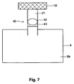
- solvent 8 may evaporate into the air and accumulate in the filter 19 over time. This can cause an emission of solvent odour on start up. It is useful to use a one-way valve 40 in the exhaust port 21, such as a ball 42 and seat 43 in the exhaust port 21. The ball 42 raises up when under pressure while the machine 1 is in operation and falls back into the seat 43 when the machine 1 is turned off. This prevents solvent vapour from accumulating in the filter 19.
- Other one-way valves 40 may be used provided they can withstand the caustic nature of the solvent 8.
Landscapes
- Chemical & Material Sciences (AREA)
- Chemical Kinetics & Catalysis (AREA)
- Physics & Mathematics (AREA)
- Thermal Sciences (AREA)
- Engineering & Computer Science (AREA)
- Mechanical Engineering (AREA)
- Treating Waste Gases (AREA)
- Separation Of Particles Using Liquids (AREA)
Abstract
Description
- This invention relates to liquid/air separators in flushing devices.
- During maintenance of an air conditioning system, including an automotive air conditioning system, it is sometimes necessary to flush the system or system components by circulating solvent solution that may be volatile and/or odourous through the system components to dissolve and remove all contaminants and oil from the system components. These contaminants and oil must be completely removed from the system components before the system can be recharged with clean refrigerant and oil. If not completely removed, the residual contaminants or oil can cause problems or system failure after the system is back in operation.
- Flush and purge machines for this purpose are known. The machine is connected to the component to be flushed. The solvent is fed from the machine through the system and back to the machine. Contaminants are dissolved by the solvent. The solvent is fed through the system for a period of time, for example half an hour.
- After the solvent has been run through the system for a sufficient time, compressed air is fed through the system to purge the solvent. Liquid solvent drops out into a tank in the machine and the air is filtered by a charcoal filter in the machine. The compressed air is typically vented into the atmosphere. The vented fumes are unpleasant, potentially hazardous to breath, and/or potentially explosive.
- Alternative systems are desirable.
- In a first aspect the invention provides a separating tank for use in a flushing machine to flush an air conditioning system using liquid solvent and to purge the solvent from the system. The tank has a chamber and an inlet port for receiving solvent-laden air and liquid. A tube is connected to the inlet port and exits into the chamber. The tube directs the solvent-laden air and liquid outwardly from the tube into the chamber. The tank also has an exhaust port from the chamber for venting air from the chamber.
- The tube may have an outward portion that is angled outwardly and downwardly to create a spinning motion of solvent-laden air and liquid. The chamber may contain walls against which at least a portion of the solvent-laden air and liquid can hit as it moves outwardly from the tube.
- The tank may also have a baffle plate dividing the chamber into a receiving compartment and an exhaust compartment. In this case, the tube exits into the receiving compartment, and the exhaust port vents air from the exhaust compartment; while, the baffle plate contains holes to allow passage of air from the receiving compartment to the exhaust compartment.
- The holes of the baffle plate may begin at a distance beneath the tube outward portion, so that at least a portion of the solvent-laden air and liquid can hit against an upper portion of the baffle plate above the holes.
- The tank may have walls that have corners where the walls meet to create additional air turbulence. The walls may be square to one another for additional air turbulence.
- The tank may have a filter on the exhaust port for removing solvent vapour. The tank may have a one-way valve for allowing air to vent through the exhaust port under pressure, while otherwise preventing air from venting through the exhaust port. The tank may be grounded to prevent sparks.
- In a further aspect the invention provides a flushing machine for use with an air conditioning system to flush the air conditioning system using liquid solvent and to purge the solvent from the system. The machine has the tank discussed above, an outlet hose for connection to the system, an air pump for forcing air into the system through the outlet hose; and a return hose for receiving solvent-laden air and liquid from the system. The inlet hose is connected to the inlet port of the tank.
- For a better understanding of the present invention and to show more clearly how it may be carried into effect, reference will now be made, by way of example, to the accompanying drawings which show a preferred embodiments of the present invention, and in which:
- Figure 1:
- is a see through perspective of a tank according to the preferred embodiment of the invention;
- Figure 2:
- is a side cross-section of a flushing machine employing the tank of Figure 1 according to the preferred embodiment of the invention;
- Figure 3:
- is a see-through front view within the flushing machine of Figure 2;
- Figure 4:
- is a plan view of the tank of Figure 1;
- Figure 5:
- is a see-through side view of the tank of Figure 1;
- Figure 6:
- is a perspective view of the flushing machine of Figure 2; and
- Figure 7:
- is a diagrammatic view of a one-way valve used in the tank of Figure 1.
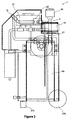
- Referring to the Figures, a
machine 1 is powered only by compressed air. Themachine 1 is connected atconnection 3 to a normal compressed air supply line, not shown, available in service locations for power. An air conditioning system, not shown, (or components to be flushed, such as an evaporator or condenser) is connected to theoutlet hose 5 of themachine 1 and to thereturn hose 7 of the machine 1 (forming a continuous loop) so that themachine 1 can circulate flushingsolvent 8 or air through the system or components and back into themachine 1. - The machine has a
receiving chamber 8b in atank 9 into which the proper amount of the desiredflushing solvent 8 is placed throughfill pipe 8c. Themachine 1 has apurge mode 11 and aflush mode 13 selected at acontrol 15. When themachines control 15 is placed in the "flush"mode 13, an air poweredpump 17 is activated and circulates the solvent out of thetank 9, through the system or components to be flushed and back into the tank. Thesolvent 8 is circulated until the system is clean. - After the flushing
solvent 8 is circulated through the components to clean them, the flushingsolvent 8 itself must then be purged from the components. The preferred method for purging the flushingsolvent 8 out of the components is to blow thesolvent 8 out by passing a high volume of compressed air through the components until allsolvent 8 is blown out and the components are completely dry. The high volume air flow forces theliquid solvent 8 out of the system components and back into thereceiving tank 9 in themachine 1. The air passes through thetank 9 and is exhausted out of thetank 9 through an activatedcharcoal filter 19 that removes thesolvent 8 vapour to prevent odour and hazardous fumes from exiting themachine 1 through itsexhaust port 21. - To accomplish this "purge", the
machine controls 15 are placed in the "purge"mode 11. Compressed air is passed through aregulator 23 to regulate to a preset pressure. The air is then passed through a condensingcoil 25 which has afan 27 power by anair motor 27a blowing air across thecoil 25 to reduce air temperature and condense out moisture. The air then exits the machine through theoutlet hose 5 and enters the components being purged. After passing through the components, the air returns to themachine 1 through thereturn hose 7. The air flow initially blows the liquid solvent 8 out of the system and then dries the system as it continues to flow through the components. The air does not circulate through the system repeatedly but rather is blown through the system, back into themachine 1 and is exhausted out of theexhaust port 21filter 19 on thesolvent tank 9. This purge continues until the components are completely dry. - Because of the high volume of air rushing through the
tank 9, without proper and complete separation, liquid solvent or saturated vapour will be carried to the exhaust filter, as is the case with machines, not shown, currently on the market. The machines currently on the market emit objectionable levels of odour and may emit hazardous levels of fumes because the exhaust air is carrying saturated vapour or even liquid solvent out through the exhaust filter. These machines do not separate the liquid solvent from the air flow adequately. - When liquid solvent or saturated vapour is carried to the exhaust filter by the air flow, the filter quickly saturates, allowing vapour and/or liquid to pass through. When this happens, the exhaust air will be very odorous and objectionable and may carry enough fumes to be hazardous.
- The
machine 1 has a receivingtank 9 that is designed to receive a high volume of liquid solvent 8 and air mixture, separate the liquid from the air completely and trap the solvent 8 in thetank 9 while allowing the air to pass through thetank 9 and exhaust out through theexhaust filter 19. Thetank 9 is designed such that the liquid solvent 8 is separated completely from the air flow and retained completely in thetank 9 before the air is exhausted. Thetank 9 design completely separates the liquid and saturated vapour from the air flow and thus prevents any liquid or any saturated vapour from reaching theexhaust filter 19. Since no liquid solvent 8 or saturated vapour reaches theexhaust filter 19, thefilter 19 can effectively filter out the vapour. Thereby, passing a clean air flow out of theexhaust port 21 of themachine 1, with no objectionable odour and no hazardous level of fumes. - The
machine 1 is powered by air to preclude any chance of electrical sparks because of the flammability of the solvent 8 to be circulated by thismachine 1. The machine 2 has a groundedinlet 7 andoutlet 5 hoses to prevent any static electricity from generating a static spark. It also hasconductive wheels 27b andconductive standoffs 27c for further grounding. - The successful operation of this
machine 1 depends upon the ability of thesolvent receiving tank 9 to completely separate the liquid solvent 8 from the air flow. Thetank 9 must separate the liquid solvent from the air, retain the liquid solvent 8 in thetank 9, and allow the air to pass out of thetank 9. If the liquid solvent 8 is not completely separate from the air, the exhaust from themachine 1 will contain excessive odour and possibly hazardous levels of fumes. Thetank 9 accomplishes separating the liquid solvent 8 from the air flow by a combination of principles. - The liquid and air mixture enters the top of the
tank 9 flowing vertically downward through asingle tube 28a fluid inlet 29. Inside thetank 9, the solvent 8/air stream is split into twoseparate tubes 28b, c, which are 180 degrees opposed to each other and which are turned angularly outward and spirally downward. As the air/liquid mixture exits the spirallingtubes 28b,c, it is spinning outward towards the sides of thetank 9 and downward toward the bottom of thetank 9. The shape of thetank 9 is square and is divided into two separate compartments A, B by a specially designedbaffle plate 31. As the liquid/air mixture exits the twotubes 28b,c, its pressure and velocity is suddenly reduced due to the expansion into a larger volume. This sudden reduction in pressure and velocity causes some of the liquid which is heavier than the air, to fall to the bottom of thetank 9, while the air spirals continue outward to the sides of thetank 9. - The spiralling, spinning action of the air stream throws more remaining liquid outward due to centrifugal force. This causes the liquid to be thrown against the
tank 9 wall and its falls to the bottom of thetank 9. - As the air stream continues to spin around inside the first compartment of the
tank 9 as indicated by arrows C, which is rectangular in shape, each time it goes past a corner of thetank 9, its flow is interrupted and slowed, and turbulence is created which causes yet more liquid to fall out of the stream or hit the corners of thetank 9 and fall towards the bottom of thetank 9. - The swirling air streams remain above the liquid solvent 8 that is collected in the bottom of the
tank 9 so that turbulence is not created in the liquid solvent 8 and liquid solvent 8 is therefore not reintroduced into the air stream. Since the solvent 8 is very volatile, and turbulence created in the liquid solvent 8 would cause the liquid solvent 8 to go back into the air stream. - The air flow which remains above the liquid solvent 8 collected in the bottom of the
tank 9 can move throughholes 33 in abaffle plate 31 as indicated by arrow D (which are located above the liquid solvent 8 level but below the entering air/liquid spirals) into a second chamber of thetank 9. To pass through theholes 33 in thebaffle 31, the air must turn 90 degrees to its direction of movement pass through theholes 33 in thebaffle 31 and then turn an additional 90 degrees to go vertically upward toward thetank 9exit exhaust port 19. The remaining heavier liquid solvent 8 cannot make the 90 degree turns (total of 180 degrees) and therefore falls out into thetank 9 bottom. - The
exhaust port 19 is located in the top of the second chamber B. Therefore, only air containing no liquid or saturated vapour can pass through theholes 33 inbaffle plate 31, into the second chamber and rise up to the exist of thetank 9. Theexhaust port 21 is further fitted with afilter 19 which can filter out the solvent 8 vapour from the air stream easily since there is no liquid solvent 8 remaining in the air stream. - Because of the
unique tank 9 design and function, only dry solvent vapour can reach theexhaust port 21 of thismachine 1. Theexhaust filter 19 can then easily remove the vapour. Therefore only clean dry air with extremely low odour level is exhausted from thismachine 1. Thetank 9 design is critical to the efficient and safe operation of thisflushing machine 1. - If the
machine 1 is left sitting liquid solvent 8 may evaporate into the air and accumulate in thefilter 19 over time. This can cause an emission of solvent odour on start up. It is useful to use a one-way valve 40 in theexhaust port 21, such as aball 42 andseat 43 in theexhaust port 21. Theball 42 raises up when under pressure while themachine 1 is in operation and falls back into theseat 43 when themachine 1 is turned off. This prevents solvent vapour from accumulating in thefilter 19. Other one-way valves 40 may be used provided they can withstand the caustic nature of the solvent 8. - It will be understood by those skilled in the art that this description is made with reference to the preferred embodiment and that it is possible to make other embodiments employing the principles of the invention which fall within its spirit and scope as defined by the following claims.
Claims (12)
- A separating tank for use in a flushing machine to flush an air conditioning system using liquid solvent and to purge the solvent from the system, the tank comprising:a chamber;an inlet port for receiving solvent-laden air and liquid;a tube connected to the inlet port and exiting into the chamber, the tube to direct the solvent-laden air and liquid outwardly from the tube into the chamber; andan exhaust port from the chamber for venting air from the chamber.
- The tank of claim 1, wherein the tube has a outward portion that is angled outwardly and downwardly to create a spinning motion of solvent-laden air and liquid.
- The tank of claim 1, wherein the chamber contains walls against which at least a portion of the solvent-laden air and liquid can hit as it moves outwardly from the tube.
- The tank of claim 1, further comprising a baffle plate dividing the chamber into a receiving compartment and an exhaust compartment; the tube exiting into the receiving compartment, and the exhaust port venting air from the exhaust compartment; the baffle plate containing holes to allow passage of air from the receiving compartment to the exhaust compartment.
- The tank of claim 4, wherein the holes of the baffle plate begin at a distance beneath the tube outward portion, so that at least a portion of the solvent-laden air and liquid can hit against an upper portion of the baffle plate above the holes.
- The tank of claim 5, wherein the walls have corners where the walls meet for additional air turbulence.
- The tank of claim 5, wherein the walls are square to one another for additional air turbulence.
- The tank of claim 1, comprising a filter on the exhaust port for removing solvent vapour.
- The tank of claim 8, further comprising a one-way valve for allowing air to vent through the exhaust port under pressure, while otherwise preventing air from venting through the exhaust port.
- The tank of claim 1, wherein the tank is grounded to prevent sparks.
- A flushing machine for use with an air conditioning system to flush the air conditioning system using liquid solvent and to purge the solvent from the system, the machine comprising:a tank as set out in claim 1;an outlet hose for connection to the system;an air pump for forcing air into the system through the outlet hose;a return hose for receiving solvent-laden air and liquid from the system; and
wherein the inlet hose is connected to the inlet port of the tank. - A flushing machine comprising:a tank as set out in any one of claims 2 through 9;an outlet hose for connection to the system;an air pump for forcing air into the system through the outlet hose;a return hose for receiving solvent-laden air and liquid from the system; and
wherein the inlet hose is connected to the inlet port of the tank.
Applications Claiming Priority (2)
| Application Number | Priority Date | Filing Date | Title |
|---|---|---|---|
| US6739697P | 1997-12-05 | 1997-12-05 | |
| US67396P | 1997-12-05 |
Publications (2)
| Publication Number | Publication Date |
|---|---|
| EP0930184A2 true EP0930184A2 (en) | 1999-07-21 |
| EP0930184A3 EP0930184A3 (en) | 2002-06-19 |
Family
ID=22075734
Family Applications (1)
| Application Number | Title | Priority Date | Filing Date |
|---|---|---|---|
| EP98309943A Withdrawn EP0930184A3 (en) | 1997-12-05 | 1998-12-04 | Flushing machine with liquid/air separating tank |
Country Status (3)
| Country | Link |
|---|---|
| US (1) | US6179904B1 (en) |
| EP (1) | EP0930184A3 (en) |
| CA (1) | CA2255018A1 (en) |
Cited By (1)
| Publication number | Priority date | Publication date | Assignee | Title |
|---|---|---|---|---|
| CN106040678A (en) * | 2016-07-25 | 2016-10-26 | 石狮市和溪汽车清洗设备商行 | Automobile air conditioner indoor pipeline omni-directional cleaning equipment |
Families Citing this family (7)
| Publication number | Priority date | Publication date | Assignee | Title |
|---|---|---|---|---|
| US6921423B2 (en) * | 2003-07-21 | 2005-07-26 | Ingersoll-Rand Company | Separator tank assembly and method of manufacture |
| US7156896B2 (en) * | 2004-05-04 | 2007-01-02 | Ramvac Dental Products, Inc. | Separating tank assembly and method of draining separating tank |
| JP2006083809A (en) * | 2004-09-17 | 2006-03-30 | Yamaha Motor Co Ltd | Engine-driven vehicle oil tank |
| JP6171194B1 (en) * | 2016-02-10 | 2017-08-02 | 三菱重工業株式会社 | Demister unit and EGR system |
| JP6150915B1 (en) * | 2016-02-10 | 2017-06-21 | 三菱重工業株式会社 | Demister unit and EGR system |
| CN109518765B (en) * | 2017-09-18 | 2020-12-08 | 讯凯国际股份有限公司 | Tanks for liquid cooling systems |
| GB2572658B (en) * | 2018-08-28 | 2020-12-02 | Vortexair Ltd | A precleaner |
Family Cites Families (15)
| Publication number | Priority date | Publication date | Assignee | Title |
|---|---|---|---|---|
| US2818133A (en) * | 1955-11-04 | 1957-12-31 | Celanese Corp | Solvent recovery |
| US2893510A (en) * | 1957-01-18 | 1959-07-07 | Delta Tank Mfg Company | Spherical separator |
| US4092137A (en) * | 1977-09-21 | 1978-05-30 | Ingersoll-Rand Company | Gas-entrained liquid separating means with dual housing |
| US4297116A (en) * | 1978-07-10 | 1981-10-27 | Aitken, Inc. | Apparatus for separating foreign matter from a gas stream |
| US4260402A (en) * | 1979-05-17 | 1981-04-07 | Ingersoll-Rand Company | Housing means for defining air/oil separator and oil reservoir assembly |
| US4516994A (en) * | 1984-04-11 | 1985-05-14 | Vilter Manufacturing Corporation | Apparatus for separating liquid droplets from gas |
| DE3419159C1 (en) * | 1984-05-23 | 1986-01-30 | Kernforschungszentrum Karlsruhe Gmbh, 7500 Karlsruhe | Degasser |
| US4688252A (en) * | 1985-12-19 | 1987-08-18 | Zenith Electronics Corporation | IV SAP/stereo audio system |
| DE3633379A1 (en) * | 1986-10-01 | 1988-04-14 | Kernforschungsz Karlsruhe | Degasser |
| US4842622A (en) * | 1988-03-31 | 1989-06-27 | Wamsley Jr Robert H | Gas/liquid/solids separator |
| US4963168A (en) * | 1989-07-21 | 1990-10-16 | Allied-Signal Inc. | Apparatus for recovering solvent from solvent laden process air streams |
| US5053126A (en) * | 1990-02-28 | 1991-10-01 | Ingersoll-Rand Company | Apparatus for gas liquid separation |
| US5599365A (en) * | 1995-03-03 | 1997-02-04 | Ingersoll-Rand Company | Mechanical fluid separator |
| US5676717A (en) * | 1995-11-13 | 1997-10-14 | Ingersoll-Rand Company | Separator tank |
| DE19617036C2 (en) * | 1996-04-27 | 2003-12-04 | Fresenius Ag | Device for separating gas bubbles from blood |
-
1998
- 1998-12-04 CA CA002255018A patent/CA2255018A1/en not_active Abandoned
- 1998-12-04 US US09/205,361 patent/US6179904B1/en not_active Expired - Fee Related
- 1998-12-04 EP EP98309943A patent/EP0930184A3/en not_active Withdrawn
Non-Patent Citations (1)
| Title |
|---|
| None |
Cited By (1)
| Publication number | Priority date | Publication date | Assignee | Title |
|---|---|---|---|---|
| CN106040678A (en) * | 2016-07-25 | 2016-10-26 | 石狮市和溪汽车清洗设备商行 | Automobile air conditioner indoor pipeline omni-directional cleaning equipment |
Also Published As
| Publication number | Publication date |
|---|---|
| US6179904B1 (en) | 2001-01-30 |
| CA2255018A1 (en) | 1999-06-05 |
| EP0930184A3 (en) | 2002-06-19 |
Similar Documents
| Publication | Publication Date | Title |
|---|---|---|
| CN101222964B (en) | System for separating a mixture and inlet device | |
| US11937764B2 (en) | Cleaning device having vacuum cleaner and docking station | |
| US8728208B2 (en) | Air cleaner | |
| US6946021B2 (en) | Air cleaner | |
| US6391100B1 (en) | Method and apparatus for cleaning a gas | |
| US6241809B1 (en) | Apparatus and method for liquid scrubbing contaminants from a gas flow | |
| CN113117401A (en) | Separating device and cleaning apparatus | |
| US6179904B1 (en) | Flushing machine with liquid/air separating tank | |
| JP6749146B2 (en) | Wet gaseous substance treatment equipment | |
| JP4906175B2 (en) | Gas-liquid separator | |
| JP7219502B2 (en) | Compressed pneumatic circuit system | |
| KR101037214B1 (en) | Acoustic resonance microorganism deodorizer | |
| US3516647A (en) | Anti-air pollution device | |
| JP2004202392A (en) | Dust removing apparatus | |
| JP2020536006A (en) | Emissions treatment equipment for vehicle air brake filling systems | |
| JP3774671B2 (en) | Exhaust air treatment device | |
| US3572010A (en) | Vapor control apparatus | |
| JPH10211407A (en) | Compressor installation with oil separation from condensate and device for separating oil from condensate used therefor | |
| JP5856776B2 (en) | Catch tank device for air dryer equipment | |
| JP3774670B2 (en) | Exhaust air treatment device | |
| JP7253839B1 (en) | Compressed pneumatic circuit structure | |
| JPH09276649A (en) | Exhaust gas treatment equipment | |
| JP2005169347A (en) | Dust removing apparatus | |
| JP2005349339A (en) | Dust-removal device | |
| JPH10113526A (en) | Air cleaner |
Legal Events
| Date | Code | Title | Description |
|---|---|---|---|
| PUAI | Public reference made under article 153(3) epc to a published international application that has entered the european phase |
Free format text: ORIGINAL CODE: 0009012 |
|
| AK | Designated contracting states |
Kind code of ref document: A2 Designated state(s): AT BE CH CY DE DK ES FI FR GB GR IE IT LI LU MC NL PT SE |
|
| AX | Request for extension of the european patent |
Free format text: AL;LT;LV;MK;RO;SI |
|
| PUAL | Search report despatched |
Free format text: ORIGINAL CODE: 0009013 |
|
| AK | Designated contracting states |
Kind code of ref document: A3 Designated state(s): AT BE CH CY DE DK ES FI FR GB GR IE IT LI LU MC NL PT SE |
|
| AX | Request for extension of the european patent |
Free format text: AL;LT;LV;MK;RO;SI |
|
| AKX | Designation fees paid | ||
| REG | Reference to a national code |
Ref country code: DE Ref legal event code: 8566 |
|
| STAA | Information on the status of an ep patent application or granted ep patent |
Free format text: STATUS: THE APPLICATION IS DEEMED TO BE WITHDRAWN |
|
| 18D | Application deemed to be withdrawn |
Effective date: 20021220 |